© 2015, IRJET ISO 9001:2008 Certified Journal Page
441
Study on Theoretical and Numerical analysis of Main frame- A
Structural part in Backhoe Loader
Vivekanand Agalagatti
1, Dr. M A Kamoji
2, S Muthukumar
31
Post graduate student, Mechanical Engineering Department, KLEMSSCET, Karnataka, India
2Professor, Mechanical engineering department, KLEMSSCET, Karnataka, India
3
Deputy General Manager, Quality department, THCM, Karnataka, India
---***---Abstract -
Fatigue is the most common cause ofmechanical failure in engineering components. Fatigue cracks usually initiate at stress concentration features and such features are almost inevitable in the design of engineering components. It is observed that the structural part called as main frame in backhoe loader by Tata Hitachi (backhoe loader is also called as the excavator) is found to have cracks at early hours of the operation. Hence it is required to examine structural part for the crack initiation, crack growth cycle and cycle at which fracture takes place. The main objective of this project is to model, analyze and understand critical structural part in structural equipment, i.e. main frame by both theoretical and numerical based calculations. Primarily this work focuses to identify different stress levels that may lead to crack initiation. It is followed by the crack propagation rate and the cycles at which the fracture takes place in the main frame.
Fatigue values are used to find S-N curves which provides information regarding probable cycles at which crack initiates. The growth rate of crack propagation is determined using Paris law of crack propagation. The theoretical results obtained are compared with numerical results. For numerical analysis modeling of structural part is done using SOLID WORKS and analysis part using ANSYS software. The fatigue life of the given structural component is,
106 cycles from theoretical stress analysis. Whereas
from ANSYS the estimated life cycle is 105.40 cycles. The
mathematical modeling and stress analysis values have marginal offset of 10%, which is acceptable and may be due to the other dynamic factors. A scheme of structure improvement is suggested in order to make the structural component to withstand high stresses, which not only improves fatigue life but also can decrease
total deformation of structural component
considerably.
Key Words:
Backhoe Loader, Fatigue, Cracks, S-N
Curves.
1. Backhoe Loader
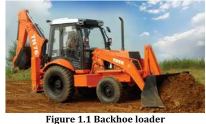
[image:1.595.328.535.477.602.2]The backhoe loader is wheeled machine, having a main frame- a welded structural frame design at the core to carry both front loader and rear Backhoe operation. When the Backhoe operation is performed the machine is stationary and digs below ground level, when used in the loader operation (bucket used), the machine dozes loads through forward motion. The Backhoe loader is shown in figure 1.1
Figure 1.1 Backhoe loader
A Backhoe work cycle normally comprises excavating, elevating, swinging and discharging materials. Loader work cycle normally comprises filling, elevating, transporting and discharging materials.
These are mainly used in construction are surface mining for moving crude materials over short distance, but because of the versatility of the machines, they are also commonly used for timber loading and similar tasks.
1.1 Main Frame
© 2015, IRJET ISO 9001:2008 Certified Journal Page
442
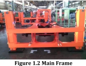
[image:2.595.84.237.206.322.2]axle, fuel tank, hydraulic tank etc. It consists of various plates welded together to form the entire structure. It is a structural part in the Backhoe loader which carries the critical stresses in working condition. It is learnt that crack producing in the early hours of the working condition is leading to total failure of the main frame- A structural member. Project work hence concentrates on the stresses acting on the main frame. Main frame is shown in figure 1.2 below.
Figure 1.2 Main Frame
2. Objective of Study
The objectives mainly focusses on theoretical analysis followed by numerical analysis and their comparison. The work also is used to suggest modifications to the mainframe of backhoe loader.
2.1 Theoretical analysis
The fatigue life of the main frame is to be found out by using S-N curves, using the fatigue stress data provided by the company. S-N curve gives results on the probable cycles at which the crack is likely to be initiated on the structural part. Further growth rate can be calculated using Paris law of crack propagation. These values explain the growth rate at which the crack is likely to propagate from one point to another point.
2.2 Numerical analysis
The main frame is to be modelled on solid works using the data provided by the Tata Hitachi Company. Further it is analysed on the ANSYS software for fatigue life and relevant calculations. These results show the stress concentration variation, fatigue life, strength of the structural component.
2.3 Comparison
Comparison between values from theoretical analysis and the numerical analysis is to be carried out. The results from the both analysis are compared in order to establish a relation between both results.
2.4 Scheme of improvement
A scheme of improvement is to be suggested to improve the fatigue life and strength of the structural component if results have not shown satisfactory results.
3. Theoretical Analysis
Theoretical analysis include finding the fatigue life of the structural member using the principal stress values provided by the company. Using the principal stress values, cycles at which probable initiation of crack may be found out. Using Paris law of crack propagation crack
growth rate can be measured. The fatigue stress values provided by the company are as follows
Data Set 1: maximum stress minimum stress,
Data Set 2: maximum stress, minimum stress,
Two set of data provided are based on different loading conditions due to which different fatigue stress data are generated. First set of data is when the bucket of backhoe loader is not in loading condition and second set of data is when the bucket of backhoe loader is in loading condition. Both set of data are used in theoretical analysis.
3.1 Minimum Stress/Cycle required for Initiation of a Crack under Working Condition
Given data set 1:
From first set of data maximum stress is 18 MPa and minimum stress is -2 MPa. It required to find mean stress, alternating stress to find the endurance limit of the structural component at particular fatigue stress.
The actual stress values based on measured values are given. How many cycles of life can be expected if ultimate yield strength is Maximum stress is
and minimum stress is . Given that = 18 MPa = -2 MPa Alternating stress,
Mean stress,
The corrected endurance limit is given by,
Endurance limit is defined as maximum value of the completely reversed bending stress which a standard specimen can withstand without failure, for infinite number of cycles.
For steel
Loading effects axial loading=0.7 Size effects=0.6
Surface effects
=57.7(841)-0.718
= 0.4583 Temperature effect,
Reliability effects,
Therefore corrected endurance limit,
To create S-N diagram we also need a number for estimated strength at 103 cycles
Assuming Se begins at 106 cycles,
© 2015, IRJET ISO 9001:2008 Certified Journal Page
443
-0.3384To find life
-0.3384
-0.3384
Log N =8.3176
Therefore, number of cycles the structural component can withstand before failure is,
N = 108.3176
Graph 3.1: Relation between Number of loading cycles and maximum stress (S/N Curve)
It is observed from the theoretical analysis that the fatigue life at maximum stress 18 MPa and minimum stress -2 MPa is 108.31 cycles. Hence the structural component is
considered to be safe.
Further a theoretical analysis is carried out at second set of data which is taken when the bucket of the backhoe loader is in loading condition. The calculations are as follows.
Given data set 2:
The actual measured stress values are given. How many cycles of life can be expected, if
is , is . And
ultimate yield strength of ms plate is .
Given that maximum stress, minimum stress,
Corrected endurance limit,
Endurance limit is defined as maximum value of the completely reversed bending stress which a standard specimen can withstand without failure, for infinite number of cycles.
Where
Loading effect, axial bending Size effect: b=500mm h=10000 mm
Therefore, =
= = 1806.57 therefore =0.6 Surface effects,
= 5707(841)-0.718
Temperature effects,
Hence, corrected endurance limit, =0.7×0.6×0.458×1×0.753×420.5=
To create S-N diagram we also need a number for estimated strength at 106 cycles.
= 0.9× = 0.9×841=
Assuming Se begins at 106 cycles,
b= Now,
Therefore, a= 9549.92
Expected life = 9549.92 N-0.3648
To find life, = 9549.92 N-0.3648
Solving for Expected life N, we get Expected life is N = 105.40 cycles.
At higher stresses the component has a short fatigue life. For steel, it is found that below the endurance limit material does not fail. The S-N curve for the above data is given as,
Graph 3.2: Relation between number of loading cycle and stress ( .
The above graph 3.2 is an approximation curve for the fatigue life. The predicted life cycle at particular loading condition is 105.41 cycles.
© 2015, IRJET ISO 9001:2008 Certified Journal Page
444
in the maximum stress value acting upon it. Hence lesser the value of maximum stress more will be the life of the structural member. By the theoretical analysis of both set of data it is observed that at 38 MPa the estimated fatigue life is 105.40 Cycles. At 18 MPa the estimated fatigue life is
108.31. Hence at 38 MPa a design modification can be
adopted in order to increase its ability to sustain high life cycle. And since the estimated fatigue life exceeds a safe margin, it is considered that the structure is safe at 18 MPa.
4 Numerical analysis
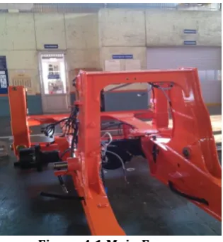
[image:4.595.83.241.298.469.2]Company has provided the related data to construct a model which is required to analyze and understand the critical structural part-Main frame. The main frame is as shown in the figure 4.1
Figure 4.1 Main Frame
4.1 Modeling of Structure
[image:4.595.326.545.394.543.2]In this case the given structural member modeled first by using SOLID WORKS. It is followed by analysis in ANSYS. SOLID WORKS gives a solid model on which stress conditions can be applied to measure the actual stresses acting on the component and locations of the stresses which are not favorable for the safety of the structural member in a structure. To analyze the part we need to first model the part. The following part is modeled using data provided by the company as shown in figure 4.2
Figure 4.2 Model of structure
This is modeled using SOLID WORKS using the data provided by the Tata Hitachi Construction equipment (THCM).
4.2 Analysis of Main Frame
SOLID WORKS is used for modeling the structure. Later the model is analyzed for the stress conditions, load positions, behavior of structure, fatigue life etc. With the help of ANSYS software.
The first set of data describes the bucket in unloading condition. The maximum stress is 18 MPa and Minimum stress is -2 MPa. Applying stress conditions on model and on analysis gives a fatigue life of more than 108.31 cycles.
Hence the Structure at this condition is considered to be safe and it need not be analyzed numerically.
Given Data 2
Stress in the compression is -171 MPa, whereas in tension it is 38 MPa. And component is assumed to be fixed at the bottom.
In an ANSYS analysis model is loaded with various kinds of loads acting on the component. As the load conditions are already given by the company, loads can be applied as shown in figure 4.3
Figure 4.3 Component in structural loading condition
The model is then meshed fine to get the more accurate results as shown in the figure 4.4
[image:4.595.334.534.591.731.2]© 2015, IRJET ISO 9001:2008 Certified Journal Page
445
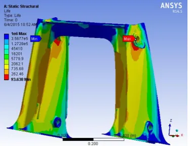
Structural analysis is carried out to get results of Fatigue life. The fatigue life is as shown figure 4.5, and total deformation of the structural member at given loading conditions is shown in figure 4.6
Figure 4.5 Fatigue life of component
Figure 4.6 Total deformation
The dark spaces on the component are the probable locations of fatigue failure as shown in figure 4.5. The total deformation is higher at the upper portion and almost zero near the fixed portion of the structural member. The life varies from minimum 94 cycles to 106 cycles. The
above analysis shows the fatigue life data of the given structural component at given data conditions. The theoretical stress analysis of the structural column using ANSYS is 106 cycles, whereas the estimated life cycle is
105.40 cycles. The mathematical modeling and stress
analysis values are marginal offset by 10%, which is acceptable and may be due to the other dynamic factors Components under such cyclic loading and working in dynamic condition will have an effect on the load bearing capacity of the structural part and may lead to fatigue failure.
Table 4.1: Comparing theoretical values with ANSYS values
Sl no
Theoretical values at 38 MPa in tension and 171 in compression
Values form ANSYS at 38 MPa in tension and 171 in compression 1 105.41 106
From the table 4.1, it is observed that the theoretical life cycle is 105.41, whereas expected life cycle from software
analysis is 106 cycles. The deviation is due the dynamic
loading conditions. But critical part is to be modified for the improvement in the life cycles and better strength of the component.
For another set of data provided by the company is that 18 MPa in tension and -2 MPa in compression. By theoretical analysis it is clear that fatigue life of the component at particular data is satisfactory. Hence the ANSYS analysis is not covered
5 Scheme of Structure Improvement
As discussed the component fails at 106 cycles as
calculated from numerical analysis and it fails at 105.40
cycles as calculated from theoretical analysis on second set of data, which is not acceptable for the design criteria. Hence the modification of the critical structure is taken into consideration to increase the fatigue strength and thereby improvement in the fatigue life of the component. It is known that the application of strips may reduce the fatigue stress acting and these lead to further improvement in it mechanical properties. Hence a strip is added to the model where the stress is higher than the safe stress. Generally there are several methods to arrest the crack. They are as follows.
5.1 Support of Strip plate on Main Frame
A strip plate can be used to arrest the crack in a structural component as discussed earlier. Hence it can also be used to support the critical structural member to withstand the fatigue failure. And it helps in increasing the strength of material thereby improving the fatigue life of the component. The strip plate is attached to the critical structural member to the inside face, where the probability of the fatigue failure is high, as shown in the figure 5.1
Figure 5.1 Small strip plate attached to component
[image:5.595.69.257.160.304.2]© 2015, IRJET ISO 9001:2008 Certified Journal Page
446
Figure 5.2 Fatigue life of striped component
It is clear from the figures 5.2 that after attaching the strip plate the fatigue life increases considerably. Comparing figures 4.5 and figure 5.2 it is observed that the minimum cycles at which the component may fail at early hour’s increases from 93 cycle to 100 cycles
Figure 5.3 Total deformation of striped component
Comparing figure 4.6 and figure 5.3 it is seen that the total deformation of the critical member is decreased from 0.0028 mm to 0.0025 mm, which shows that the strip plate not only increases fatigue life but also the strength of the component.
CONCLUSION
Tata Hitachi had facing a design related problem with main frame in the backhoe loader. Cracks are generated on the main frame at early hours of operation. These cracks further were cause for the failure of the main frame. Hence the task is to reveal cause for the generation of the cracks on main frame. For that finding the fatigue life of main frame is necessary. Endurance limit, and total deformation are calculated.
A procedure has been followed which include finding fatigue results using theoretical analysis, and numerical analysis. Then a comparison is made between theoretical and numerical analysis. Further a modification is suggested to improve the mechanical properties of the main frame.
Conclusions on theoretical analysis
A theoretical analysis is carried out to determine the endurance limit and fatigue life of main frame structure. To compare the fatigue life two set of data are used which are provided by the company.
1. First set of data is obtained when the backhoe loader is not in loading condition. The maximum stress is 18 MPa and minimum stress is -2 MPa. The fatigue life calculated is 108.31 cycles. Hence
the structural component is considered to be safe. 2. Second set of data is obtained when the backhoe
loader is in loading condition. When a maximum stress 38 MPa and minimum stress -171 MPa is used for calculation the fatigue life is 105.40 cycles,
which is not acceptable according to design criteria. Hence the modifications on structure can be made to improve its mechanical properties This study proved, as the stress is reduced, the ability of the structural members to withstand cyclic operation load improves.
A case study on crack propagation life is done using Paris law which showed, as the maximum stress reduces crack propagation life NP also increases. With the maximum
stress increasing, critical length of the fracture decreases.
Conclusions on numerical analysis
The numerical analysis is done using the model created on Solid Works using 2-d dimensions available at the company.
The theoretical stress analysis of the structural column using ANSYS is 106 cycles, whereas the estimated life cycle
is 105.40 cycles. The mathematical modeling and stress
analysis values are marginal offset by 10%, which is acceptable and may be due to the other dynamic factors. Modeling and stress analysis of the structural member showed that key stress acting areas in the structural member subjected to this study which is in-line with the loading pattern.
Scheme of modification
© 2015, IRJET ISO 9001:2008 Certified Journal Page
447
References
[1]. N. Pugno, M. Ciavarella, P. Cornetti, A. Carpinteri “A generalized Paris’ law for fatigue crack growth.” Journal of the Mechanics and Physics of Solid 54 (2006) 1333–1349.
[2]. Yen Yin, Gilbert Y Grondin, Alaa E Elwi “fatigue crack behavior in mine excavator.” Structural engineering report No. 265 University of Alberta, May 2006.
[3]. Haresh K Vaniya, V D Sonara, Arvind Sorthiya “Analysis of Backhoe Loader Chassis for Weight & Cost Reduction using FEA - A Review Paper.” IJIRST – International Journal for Innovative Research in Science & Technology| Volume 1 | Issue 8 | January 2015 ISSN (online): 2349-6010
[4]. Anastasios G. Gavras, Diana A. Lados, J. Keith Donald “A unified method of design for fatigue crack growth resistance in structural materials.” International Journal of Fatigue 47 (2013) 58–70
[5] Long Tian, Wei Zhang, Hai-bo, Wang “Study on Finite Element Method of Power Working Device of Hydraulic Excavator.” 2011 International Conference on Electronic & Mechanical Engineering and Information Technology, 978-l-61284-088-8/ll/ ©2011 IEEE 4216 12-14 August, 2011.
[6]. Fernand Ellyin, Folarin Ozah, Zihui Xia “3-D modelling of cyclically loaded composite patch repair of a cracked plate.” Composite Structures 78 (2007) 486–494
[7]. Dhawal Kadhu, Prashnt Achawat “analysis of chassis of backhoe loader.” The Indian mining and engineering journal Vol.53 no.07 July 2014 pp. 12-16.
[8]. Experimental stress analysis – Srinath, Lingaih, Raghavan, Ramachandran and Pant Tata McGraw Hill, 1984.
[9]. Failure of materials in mechanical design, Jack A Collins, Jon Wiley New York 1992