Abstract— Steel plate Concrete (SC) with cross ties has been proven to be an effective structural system for the construction of shear walls for tall buildings, shield buildings of Small Modular Reactors (SMR) and AP1000 nuclear power plants. By incorporating Ultra-High Performance Concrete (UHPC), which features a compressive strength higher than 150 MPa and self-consolidating characteristics, rapid construction of S-UHPC modules with thinner and lighter modules will be facilitated. Furthermore, with a high strength and dense microstructure of UHPC, this structural system would be able to withstand harsh environments and mechanical loads anticipated during the service life of the structure. This paper presents the structural performance of two Steel-plate Ultra-High Performance Concrete (S-UHPC) beams and focuses on finite element simulation of the S-UHPC beams with emphasis on shear and bond behavior. The Cyclic Softened Membrane Model is utilized and a new constitutive model that accounts for the bond-slip behavior of steel plates is proposed and implemented into a finite element (FE) analysis program based on the frame work of OpenSees. The proposed FE simulation is able to capture the shear behavior of the tested S-UHPC beams.
Index Terms— Steel plate Concrete (SC), UHPC, Finite Element Simulation, OpenSees, Shear.
I. INTRODUCTION
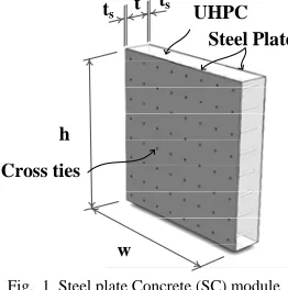
Teel plate Ultra High Performance Concrete (S-UHPC) is a composite structural system comprising of two layers of steel plates and a sandwiched UHPC layer in between, as shown in Fig. 1. In this composite structure system, two ends of each connector (cross tie) are welded on steel plates to connect the steel plates and UHPC. In recent years, Steel plate Concrete (SC) has been widely used for buildings and nuclear containment structures to resist lateral forces induced by severe earthquakes and
Manuscript received March 04, 2016; accepted March 27, 2016. This work was supported in part by the U.S. Department of Energy NEUP program (Proj. No. CFP-13-5282).
Jamshaid Sawab is with the University of Houston, Houston, TX 77204 USA. (e-mail: [email protected]).
C. H. Luu is with the University of Houston, Houston, TX 77204 USA. (e-mail: [email protected]).
Y. L. Mo is with the Civil and Environmental Engineering Department, University of Houston, Houston, TX 77204 USA, (Corresponding author, phone: (713) 743-4274; fax: (713) 743-4260; e-mail:
Mo Li was with the University of Houston, Houston, TX 77204 USA and currently with University of Irvine, Irvine, Ca 92697 USA (e-mail: [email protected]).
heavy winds. Compared to the conventional reinforced concrete, SC has higher strength and ductility, enhanced stiffness and large energy dissipation capacity [1], [2].
SC modules have good potential for small modular reactors (SMR) because of their cost-effectiveness and reduced construction time. In this paper, a new type of ultra-high performance concrete (UHPC) is used instead of conventional concrete in SC modules. The UHPC can improve the design by using less concrete and steel, taking advantage of the high strength and durability of UHPC. As a result, design and construction with optimized efficiency, compactness and reduced costs can be achieved. The modularity and ease of assembly of Steel plate UHPC (S-UHPC) beams and walls addresses the high cost barriers of typical nuclear power plants, and can provide large benefits to the electric power industry.
h
w ts
t
ts UHPC
Steel Plate
[image:1.612.362.493.383.515.2]Cross ties
Fig. 1 Steel plate Concrete (SC) module
From the mechanics point of view, S-UHPC structures can take the full advantage of individual material strength if the integrity between two distinct materials is achieved. Various methods are used to ensure the force transfer mechanism between the steel plate and concrete, such as: tie bars, shear studs, J-hooks, and profiled/surfaced preparation on steel plates [3]. In practice, cross ties, also known as tie bars or transverse bars, which connect the two external steel plates and fully embedded in concrete, are the most buildable, efficient and reliable form of SC construction in terms of time, cost, and quality control [4], [5]. SC with cross ties overcomes some of the on-site construction problems of the steel plate concrete construction that uses shear studs instead of cross ties [6].
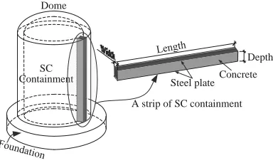
Figure 2 shows a SC nuclear containment vessel and a strip of the cylindrical wall. At the regions close to foundation and at the connections with other structural components, a SC nuclear containment is subjected to out-of-plane shear [7].
Finite Element Simulation of Steel Plate Ultra
High Performance Concrete Composite
Modules Subjected to Shear
Jamshaid Sawab, C. H. Luu, Y. L. Mo and Mo Li
SC Containment
Dome
Concrete Depth
[image:2.612.90.282.50.168.2]A strip of SC containment Steel plate
Fig. 2 SC nuclear containment and a cut strip
For the purpose of shear design of RC and PC members, ACI 318 Code [8] provides the limit on minimum amount of shear reinforcement to ensure a ductile failure mode. For the design of S-UHPC members in current AP1000 nuclear power plants, there are currently no provisions given in any code. Although, for the design of SC members with conventional concrete, ACI 349 Code [9], which adopts the provisions of ACI 318 Code, has been used by design engineers, a research program conducted by the authors shows that the ACI 349 code’s requirement for minimum amount of cross ties is insufficient [10]. When UHPC is used in SC structures, large-scale experiments need to be conducted to understand the structural behavior and determine the minimum amount of cross ties. This paper reports a series of SC beam tests cast with Ultra-High Performance Concrete and the development of a rational finite element model for the analysis of the same.
Experimental investigations have shown that the stiffness of SC composite structural system is largely dependent upon the efficiency of the shear connectors that connect the steel plates to the concrete [4], [11]. The stiffness of the shear connectors is always limited, therefore, the longitudinal shear generated at the interface between the steel plate and the concrete leads to the slip between them. The bond-slip behavior has a significant influence on the behavior of S-UHPC members, such as stiffness, deflection, strength and failure mode, etc. [12], [13]. Pronounced bond-slip between the bottom steel plate and the concrete was observed in the series of tests conducted by the authors [10]. For the purpose of this study, OpenSees [13], an object-oriented programming framework is chosen as the finite element analysis software. OpenSees, which stands for Open System for Earthquake Engineering Simulation, was developed in the Pacific Earthquake Engineering Center (PEER). It is an open-source framework that allows researchers to implement their proposed material model. The source code is openly available to the structural engineering research community to evaluate and modify. Using the OpenSees framework, material models developed by the University of Houston research group for predicting the shear behavior of reinforced concrete were implemented into a finite element analysis program called Simulation of Concrete Structure (SCS) [14]. In this paper, the SCS program will be extended by adding a new proposed model for bond-slipped steel plates to predict the structural behavior of the tested S-UHPC beams.
II. EXPERIMENTAL PROGRAM A. Ultra-High Performance Concrete (UHPC)
The UHPC developed for the purpose of this study contains cement, fine sand, ground quartz, silica fume, silica powder, high-range water reducer (HRWR) and water. Low water to cement ratio was used to achieve high compressive strength, as well as fine grains for high packing density.
Mineral admixtures such as silica fume and fly ash were used. Silica fume was found to be the most effective means of manufacturing very high strength concrete. In the form of ultra-fine particles, silica fume functions as micro-fillers, and its pozzolanic reaction improves the packing density of the matrix. It also prevents segregation caused by the use of large quantities of HRWR.
The solid particles also include round quartz crystalline silica that is chemically inert with >99.7% silicon dioxide content. Unground silica passing the sieve size of 850 micron is used as coarse sand, and ground silica (GS) passing the sieve size of 212 micron is used as fine sand. Fine ground silica (FGS) in the form of white powder is used as micro-filler for better packing density. Median diameter of the fine ground silica is 1.6 micron, and 96% of the powder has a diameter smaller than 5 micron. High-range water reducer is used to achieve good workability with a very low water-cement ratio for self-consolidating UHPC. The particle size distribution and the effect of different ingredients on the properties of UHPC have been presented in a paper published by the authors [15].
The developed UHPC which features a compressive strength of more than 150 MPa, can be robustly processed at large scale with commercially available ingredients and equipment, and meet self-consolidating. Particle size distribution for optimum packing density, the physical and chemical parameters of ingredients, and the resulting microstructure after hydration are considered essential for the design of self-consolidating UHPC.
B. S-UHPC Beams with Cross Ties
Fig. 3 Elevation of S-UHPC beam
The diameter of the rebars and the spacing (S) of the cross ties were calculated based on the designed shear reinforcement ratio. No. 3 rebars were used as the shear reinforcement and grade 70 high strength steel conforming to ASTM/ASME SA 516 was used as the top and bottom steel plates. HBM Spider 8 DAS was used to continuously record the data from the load cells, LVDTs and strain gauges. In addition, the real-time plots of strains in concrete, cross ties, and steel plates were used to observe and monitor the structural behavior of the specimen during the tests. The diameter of the rebars and the spacing (S) of the cross ties were calculated based on the designed shear reinforcement ratio. No. 3 rebars were used as the shear reinforcement and grade 70 high strength steel conforming to ASTM/ASME SA 516 was used as the top and bottom steel plates. The typical elevation of S-UHPC beam is shown in Fig. 3.
[image:3.612.345.509.300.432.2]The beams were subjected to vertical loading at each actuator with a capacity of 2670 kN, as shown in Fig. 4. The MTS Flex system was used to control the loads and displacements of the actuators. The displacement control feature was essential in capturing the post peak behavior of S-UHPC beams. Loading steps in the loading protocol were planned for a constant loading rate of 2.5 mm per 15 minutes. Each end of the beams was tested individually. In this paper, three sides, S-UHPC1 (South) and S-UHPC2 (North and South) were selected to validate the finite element program.
Fig. 4 Test setup of specimen
Table I shows the experimental matrix and the summary of the results for the three ends of S-UHPC beams. Based on the test results, the minimum shear reinforcement ratio ( ) is recommended to ensure ductile behavior of S-UHPC beams. For SC beams with Ultra-High Performance Concrete (UHPC), the minimum shear reinforcement ratio ( ) of 10% more than the minimum required by ACI 349 code ( ) is recommended.
III. FINITE ELEMENT PROGRAM A. Material Models for FEM
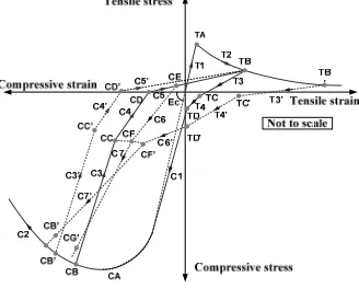
CSMM Model for Concrete with Embedded Cross Ties To analyze the shear behavior of S-UHPC structures, Cyclic Softened Membrane Model (CSMM) can be used [18] [19]. The web of the S-UHPC beam, which is comprised of UHPC and embedded cross ties, can be treated as regular reinforced concrete structure. The CSMM model is capable of accurately predicting the pinching effect, the shear ductility and the energy dissipation capacities of RC members [20]. CSMM includes the cyclic uniaxial constitutive relationships of concrete and embedded mild steel. The characteristics of these concrete constitutive laws include: (1) the softening effect on the concrete in compression due to the tensile strain in the perpendicular direction; (2) the softening effect on the concrete in compression under reversed cyclic loading; (3) the opening and closing of cracks, which are taken into account in the unloading and reloading stages, as shown in Fig. 5.
Fig. 5 Envelop of stress-strain curve of concrete
The characteristic of embedded mild steel bars include: (1) the smeared yield stress being lower than the yield stress of bare steel bars and the hardening ratio of steel bars after yielding is calculated from the steel ratio, steel strength and concrete strength; (2) the unloading and reloading stress-strain curves of embedded steel bars take into account the Bauschinger effect, as shown in Fig. 6.
Bond Slip-based Constitutive Model for Steel Plates
The experimental results show that the tested SC beams had a bond-slip characteristic before reaching its flexural or shear capacities. In other words, the bond between concrete and steel plate was not sufficient to transfer the stress in the steel plate to concrete in S-UHPC beams. Therefore, the constitutive model of the typical mild steel cannot be used for the steel plate in FE analysis.
TABLEI
EXPERIMENTAL MATRIX AND RESULTS
Specimen S (cm) fc’ (MPa) (t,ACI) (%) t,test/ (%) t,test/
t,ACI Fpeak
*
(kN) Ductility δ** Failure Mode
S-UHPC-1 South 25.4 154.0 0.170 0.184 1.08 220.5 1.003 Ductile
S-UHPC-2 North 14.6 153.89 0.170 0.323 1.90 381.7 4.010† Ductile
S-UHPC-2 South 17.1 153.89 0.170 0.277 1.63 345.6 2.650 Ductile
Notes: * peak shear capacity, ** shear ductility (deflection at the peak /deflection when cross ties yielded) † flexural ductility
S: center-to-center spacing of cross ties,fc': specified concrete compressive strength,t, ACI: minimum shear reinforcement ratio of SC beams specified
[image:3.612.73.298.431.522.2] fs
u y
n
f
y
f
si,fi
n
p
si1,fi1
[image:4.612.116.257.47.171.2] s
Fig. 6 Envelope of stress-strain curve of shear reinforcement (cross ties)
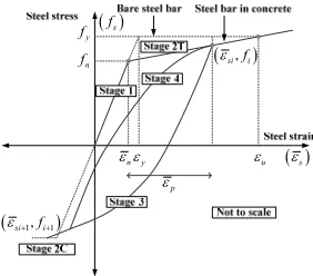
In this study, a new constitutive model for steel plate, called bond slip-based model, is proposed. Due to the bond slip, the model will take into account the reduction of both the nominal yield stress and the elastic modulus. The stress and strain curve for the bond slip-based model, shown in Fig. 7, is comprised of three parts: (1) The linear elastic part up to yield stress , which is smaller than the yielding stress of the typical mild steel; (2) the plastic part at which the steel plate continues to deform under constant load up to a strain of three times the strain at yielding; (3) the descending region at which the bond between the steel plate and concrete has been weakened and the member would fail. The negative slope of the curve in this part is proposed to capture the descending portion of the load-deflection curve of SC structures. It is assumed that the stress would drop to 20% of the peak to avoid any convergence problems in the finite element analysis.
s
f
y
f
y
s
E
slip
E
yslip
f
3y s
0.2fyslip
[image:4.612.327.544.66.227.2]10y
Fig. 7 Stress-strain relationship for Steel
To determine the yield stress of the bond slipped steel, , a free body diagram is considered between the point of application of the load and the end of the beam, as shown in Fig. 8. As it can be seen from the figure, the shear transfer in the case of steel-plate concrete structures happens across a plane at the interface of steel plate and concrete. Therefore, a shear friction model should be used to find the relationship between the shear transfer strength and the reinforcement crossing the shear plane. An equation from ACI 318-11 [8] provision, which is used to estimate the shear transfer strength of reinforced concrete when the shear reinforcement is perpendicular to the shear plane, was adopted to determine the shear friction strength between concrete and steel plate, in which the nominal shear strength
is given by
1 0.8
n sv yv c
V A f A K (1)
where is the area of concrete section resisting shear transfer, is the area of cross ties within the transfer
length, fyv is the yield strength of the cross ties. K1 is the maximum bond stress between concrete and steel plate.
V
z a
V
Shear stress T
UHPC Steel Plates Cross Ties
Point A
Fig. 8 Free-body diagram
Equation (1) can also be written as
0.8 1
n sv yv
V b z a f K
(2) Where is the beam width, is the shear span, is the distance from the center of the support to the end of the beam, is the percentage of cross ties within the transfer length.
In the right side of Eq. (1), the first term represents the contribution of cross ties to shear transfer resistance. The coefficient 0.8 represents the coefficient of friction. The second term characterizes the sum of the resistance provided by friction between the rough surfaces of concrete and steel plate and the dowel action of the cross ties [8]. To maintain equilibrium condition, the nominal shear strength given in Eq. (1) needs to be balanced by the total tensile strength of the bottom steel plate, which can be expressed as
max yv sb
T f A
(3) where is the total area of the bottom steel plate and “t” is the thickness of the steel plate.
Based on Eq. (2) and Eq. (3), the yield stress of the bond slip-based steel can be determined and expressed by Eq. (4).
1
0.8
yslip sv yv y
z a
f f K f
t
(4)
By keeping the yield strain of the bond-slip unchanged compared to the normal mild steel, the modulus of elasticity for bond slip-based steel can be calculated by Eq. (5), which has already taken into account the reduced stiffness due to bond slip.
yslip slip
y
f E
(5)
Maximum Bond Stress between Concrete and Steel Plate
As it can be seen from Eq. (4), to determine the yield stress of the bond slip-based steel, the maximum bond stress between UHPC and steel plate, needs to be specified. From the test results, it was observed that the maximum bond stress between UHPC and steel plate was affected by the amount of cross ties. In this study, the value of is calibrated using regression analysis.
Taking a moment equilibrium at point A in the free-body diagram (Fig. 8) and using the effective depth
[21], the maximum bond stress between concrete and steel plate can be written as
max
1 0.8
0.9 sv y
V a
K f
db z a
[image:4.612.99.265.397.509.2]TABLE II
CALCULATION OF K1 FOR THE TESTED S-UHPC BEAMS Specimen b
(mm) t (mm)
a/d
(%)
fy
(MPa)
f’c
(Mpa)
jd
(mm) Vmax
(kN) K1 (MPa)
S-UHPC1 South 305 6.350 2.5 0.184 413 154.0 402 220.47 1.060
S-UHPC2 North 305 6.350 2.5 0.321 413 153.9 402 382.21 1.830
S-UHPC2 South 305 6.350 2.5 0.274 413 153.9 402 345.66 1.709
where is the peak shear force obtained from the test results.
[image:5.612.92.302.269.420.2]Table II shows the calculation results of K1 for the tested S-UHPC beams. The value of K1 is normalized with the percentage of cross ties and the square root of concrete strength and plotted against a/d ratio in order to perform regression analysis for finding the relationship between the normalized value of K1 and the a/d ratio, as illustrated in Fig. 9.
After performing the regression analysis, the expression for for S-UHPC beams was found to be
(7)
Fig. 9 K1 and a/d relationship of S-UHPC beams
B. Implementation of Models to SCS
The CSMM model was implemented by Mo et al [14]. The model includes two uniaxial material classes, ConcreteZ01 and SteelZ01, and one NDMaterial class, RCPlaneStress. The ND material is related with SteelZ01, ConcreteZ01 to determine the tangent material constitutive matrix and to calculate the stress of the quadrilateral element that is used for modeling of concrete and cross ties.
Additionally, a new uniaxial material class, so-called BondSlipSteelK01, which is based on the proposed bond slip-based steel model, is implemented for modeling of steel plates. The new material class is developed by modifying the envelope curve of Hysteretic material class available in OpenSees. For each trial displacement increment in the analysis procedure, BondSlipSteel will receive the strain from the nonlinear fiber truss element, determine the tangent material matrix and calculate the stress of the element based on the stress-strain curve of the proposed bond slip-based steel model (Fig. 7). The tangent material matrix is used to formulate the element stiffness matrix, and the stress is used to compute the force resistance of the truss element.
C. Finite Element Simulation and Validation
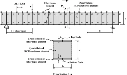
Finite element analyses were conducted on the tested S-UHPC beams. The finite element mesh and the boundary condition for the S-UHPC beam are shown in Fig. 10. The top and bottom flanges of the beam, which includes steel
[image:5.612.321.532.286.411.2]plates, were modeled using 44 2-node nonlinear truss elements with fiber section. The truss element only resists tensile and compressive forces, thus, the mesh of 2x2 for fiber section was sufficient to capture the structural response of the steel plates. The web of the beam, which was comprised of UHPC and cross ties, was simulated using total 22 4-node quadrilateral elements. RCPlaneStress and BondSlipSteel materials were assigned to the quadrilateral and truss elements, respectively. The applied load was applied to one node in the top flange of the beam. The location of the applied load depends on the end of the S-UHPC beam being tested.
Fig. 10 Finite element mesh of SC beams
The analyses were performed monotonically by displacement control schemes. The vertical loads were applied by the predetermined displacement control on the vertical displacement of the referenced node located under the load. The common displacement increment used in the analyses was 0.5 mm. Convergence was obtained quite smoothly during the monotonic analyses. The modified Newton-Raphson method was used as the solution algorithm. The nodal displacement and corresponding vertical forces were recorded at each converged displacement step, and the stress and strain of the elements were also monitored.
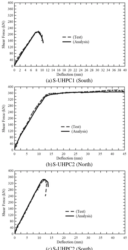
(a)S-UHPC1 (South)
(b)S-UHPC2 (North)
[image:6.612.73.295.48.479.2](c)S-UHPC2 (South)
Fig. 11 Simulated and experimental shear force-deflection curves
IV.CONCLUSIONS
In this paper, a new analytical model was developed to predict the structural behavior of S-UHPC beams subjected to shear. The investigated S-UHPC beams showed complex structural behavior, which was a combination of shear behavior of concrete web with cross ties and flexural bond-slip behavior of steel plates. The CSMM model, which had been developed for simulation of shear behavior for RC structure was utilized to capture the shear behavior of concrete web with cross ties. Additionally, a new constitutive model was proposed to account for the bond-slip behavior of steel plates. The proposed model was successfully implemented into a finite element analysis program SCS based on the framework of OpenSees. The developed program was capable of accurately predicting the shear force-displacement curves of all the tested S-UHPC beams. The finite element simulation developed in this paper provides researchers and engineers with a powerful tool to perform analysis of S-UHPC structures.
REFERENCES
[1] Braverman J., Morante R. and Hofmayer C. (1997), "Assessment of modular construction for safety-related structures at advanced nuclear power plants (NUREG/CR-6486, BNL-NUREG-52520)": Brookhaven national laboratory.
[2] Kim C. H., Lee H. W., Lee J. B. and Noh S. H. (2007), "A study of fabrications of Steel Plate Concrete (SC) modular systems for nuclear power plants", Korean Nuclear Society Autumn Meeting. PyeongChang, Korea
[3] Subedi, N. (2003). “Double skin steel/concrete composite beam elements: experimental testing.” Structural Engineer, 81(21), 30-35. [4] Xie, M., N. Foundoukos and J. Chapman. (2007). “Static tests on
steel-concrete-steel sandwich beams.” Journal of Constructional Steel Research, 63(6), 735-750.
[5] Ramesh, S. (2013), “Behavior and design of earthquake-resistant dual-plate composite shear wall systems”, Ph. D. Dissertation, Purdue University, West Lafayette.
[6] Bowerman H. and Chapman J. C. (2000), "Bi-Steel steel-concrete-steel sandwich construction", Composite Construction in Steel and Concrete IV, American Society of Civil Engineers. Banff, Alberta, Canada
[7] Oesterle R. G. and Russell H. G. (1982), “Research status and needs for shear tests on large-scale reinforced concrete containment elements.” Nuclear Engineering and Design, 69(2), 187–194
[8] ACI Committee 318 (2011), “Building code requirements for structural concrete (ACI 318-11) and commentary”. Farmington Hills, MI: American Concrete Institute.
[9] ACI Committee 349 (2006), “Code Requirements for Nuclear Safety-related Concrete structures: (ACI 349-06) and Commentary”. Farmington Hills, Michigan: American Concrete Institute.
[10] Qin F., Tan S., Yan J., Li M., Mo Y. L. and Fan F. (2015). Minimum shear reinforcement ratio of steel plate concrete beams. Materials and Structures, 1-18
[11] Coyle N. R. (2001), “Development of fully composite steel-concrete-steel beam elements”, Ph. D. Dissertation. Dundee, University of Dundee.
[12] Foundoukos N. (2005), “Behaviour and design of steel-concrete-steel sandwich construction”, Ph. D. Dissertation. London, University of London, Imperial College of Science, Technology and Medicine. [13] OpenSees (2013). "Open System for Earthquake Engineering
Simulation." from http://opensees.berkeley.edu/.
[14] Mo Y. L., Zhong J. and Hsu T. T. C. (2008), “Seismic simulation of RC wall-type structures.” Engineering Structures, 30(11), 3167-3175. [15] Mo Li, Ing Lim, Jamshaid Sawab, and Y.L Mo, "Self-consolidating
Ultra-High Performance Concrete for small modular reactor construction," in SMiRT-23, Manchester, UK, 2015.
[16] Varma, A. H., Sener, K. C., Zhang, K., Coogler, K., and Malushte, S. R. (2011). “Out-of-plane Shear Behavior of SC Composite Structures,” International Association for Structural Mechanics in Reactor Technology 21.
[17] Kani, G. N. J. (1964). "The riddle of shear failure and its solution", ACI Journal Proceedings, 64(4): 441-467.
[18] Mansour M. and Hsu T. T. C.(2005a), “Behavior of reinforced concrete elements under cyclic shear. I: Experiments.” Journal of Structural Engineering, 131(1), 44-53.
[19] Mansour M. and Hsu T. T. C. (2005b), “Behavior of reinforced concrete elements under cyclic shear. II: Theoretical model.” Journal of Structural Engineering, 131(1), 54-65.
[20] Hsu T. T. C. and Mo Y. L. (2010). Unified theory of concrete structures: John Wiley & Sons.