1
Review
1
Coherently Driven and Superdirective Antennas
2
Alex Krasnok
3
1 Advanced Science Research Center, City University of New York, New York, NY 10031, USA;
4
5
Abstract: Antennas are crucial elements for wireless technologies, communications and power
6
transfer across the entire spectrum of electromagnetic waves, including radio, microwaves, THz and
7
optics. In this paper, we review our recent achievements in two promising areas: coherently
8
enhanced wireless power transfer (WPT) and superdirective dielectric antennas. We show that the
9
concept of coherently enhanced WPT allows improvement of the antenna receiving efficiency by
10
coherent excitation of the outcoupling waveguide with a backward propagating guided mode with
11
a specific amplitude and phase. Antennas with the superdirectivity effect can increase the WPT
12
systems performance in another way, through tailoring of radiation diagram via engineering
13
antenna multipoles excitation and interference of their radiation. We demonstrate a way to
14
achieving the superdirectivity effect via higher-order multipoles excitation in a subwavelength
15
high-index spherical dielectric resonator supporting electric and magnetic Mie multipoles. Thus,
16
both types of antenna discussed here possess a coherent nature and can be used in modern
17
intelligent antenna systems.
18
Keywords: Antennas, Coherently Driven Antennas, Superdirective Antennas
19
20
1. Introduction
21
An antenna is a key element for many vital wireless technologies, including communications
22
and power transfer[1]. First antennas emerged at the same time with the discovery of electromagnetic
23
waves by H. Hertz in 1888 and since then have been developing with human civilization often being
24
a catalyst for its development. A plethora of antennas have been invented in the radio and microwave
25
frequency ranges, including microstrip antennas[2], reflector antennas[1,3], dielectric antennas[4,5]
26
to mention just a few. More recently, so-called nanoantennas or antennas operating in the optical
27
frequency range have been invented, which become irreplaceable elements for quantum optics and
28
communications on a chip[6–10].
29
While wireless communications are rather established, the wireless power transfer (WPT),
30
proposed at the beginning of the 20th century by N. Tesla is experiencing a rebirth. It was caused by
31
an experimental demonstration in Ref.[11] that the WPT efficiency can be drastically enhanced when
32
the power is transferred via resonant coupling. In that paper, wireless energy transfer between two
33
metallic coils over the distance of 2 m with 45% efficiency in the kHz range via strongly coupled
34
magnetic resonances was demonstrated[11]. These fascinating results have given rise to many novel
35
technologies, include implanted devices, electric vehicles, and consumer electronics[12]. Since then,
36
significant research efforts have been devoted to exploring the ways to achieve as high WPT
37
efficiency as possible[13], whereas the main part of them has been concentrated on optimizing of
38
electromagnetic resonators’ geometry, surrounding material, their relative arrangement.
39
40
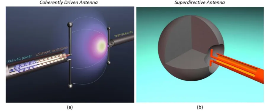
Figure 1. (a) Operation principle of coherently enhanced wireless power transfer: a transmitting
41
antenna (right) radiates radio waves to the receiving antenna (left) driven by an additional wave sent
42
from the circuit to the antenna (red wave). (b) Superdirective dielectric antenna: subwavelength
43
spherical dielectric resonator (shape can be different) with a small notch on its surface fed by a short
44
dipole source placed into the notch. Inhomogeneous near field of the dipole source excites high-order
45
multipoles in the resonator which radiate coherently and can form the superdirectivity regime.
46
On another hand, designing of highly directive antennas is a significant problem in the theory
47
of antennas, which has been worrying researchers and engineers for a long time. The importance of
48
highly directional antennas for wireless interconnections and power transfer can be understood
49
considering the Friis equation (for matched antennas)
50
2
* 0
rec
|
|
2 tr(4
)
r t r t r t
P
D D
P
d
=
a a
, (1)51
which says that the transmitted power (
P
rec) scales as product of receiver and transmitter antennas’52
directivities (
D D
r t ) and also depends on their radiation efficiencies (
r and
t ), operation53
wavelength (
0), separation distance (d
), relative polarization ( *r
ta a
), and total transmitted power54
(
P
tr). Hence, if directivities of the both antennas are the same (D
) then the transmitted power scales55
as
D
2, and hence can be significantly enlarged by using more directive antennas. There are various56
geometrical dimensions, including Yagi-Uda antenna, lens antenna, leaky-wave antenna, and others.
58
All these approaches rely on the radiated (received) wave propagation in the antenna structure and,
59
in result, these antennas have a large size (
l
0 ) in at least one direction. However, many60
application areas require an antenna to be directive and compact (
l
0) at the same time. Such61
antennas whose size is smaller than the operation wavelength in all three directions and directivity
62
much larger than the directivity of a short dipole antenna (1.5) are called superdirective antennas[14–
63
21]. Superdirective antenna operation relies on creating rapidly spatially oscillating currents in a
64
subwavelength area, which leads to excitation of higher multipoles[14,21]. In result, the antenna
65
becomes directive despite its subwavelength volume. Usually the superdirectivity regime is achieved
66
in arrays of short dipoles, which of them fed with a specific amplitude and phase. This approach
67
appeared to be unstable and energy-consuming and, in result, did not find a widespread practical
68
application.
69
In this paper, we present our recent achievements in coherently enhanced wireless power transfer
70
and superdirective antennas[21–23]. Figure 1(a) demonstrates schematically the operation principle of
71
coherently enhanced wireless power transfer. Any WPT system consists of at least two antennas:
72
transmitting and receiving ones. The transmitting antenna (right) radiates radio waves toward
73
receiving antenna (left), which receives some power. We have demonstrated that the same receiving
74
antenna driven by an additional wave (red wave) can either receive more power that it did without
75
the coherent excitation or become more stable to changes in environment or relative arrangement.
76
Next section in dedicated to such coherently enhanced WPT antennas. Figure 1(b) demonstrates the
77
superdirective dielectric antenna consisting of a subwavelength spherical dielectric resonator (shape
78
can be different) with a small notch on its surface and fed by a short dipole source placed in the notch.
79
Inhomogeneous near field of the dipole source excites high-order multipoles in the resonator which
80
radiate coherently and can form the superdirectivity regime. This approach is discussed in the Section
81
3.
82
2. Coherently enhanced wireless power transfer
83
The concept of coherently enhanced WPT is based on the fundamental property of the wave
84
nature of electromagnetic field - interference. Only recently it has been clearly emphasized that
85
electromagnetic processes such as absorption and scattering may be effectively controlled via
86
coherent spatial and temporal shaping of the incident electromagnetic field. For example, a coherent
87
perfect absorber (CPA) is a linear electromagnetic system in which perfect absorption of radiation is
88
achieved with two or more incident waves, creating constructive interference inside an absorbing
89
structure. In this section, we show that the same principle that underlies the operation of CPAs can
90
the receiving antenna [see Figure 1(a)] with an auxiliary signal, tuned in sync with the impinging
92
signal from the transmitting antenna, it is possible to enhance the efficiency and robustness of the
93
WPT system. This additional signal improves energy transfer through constructive interference with
94
the impinging wave, compensating any imbalance in the antenna coupling without having to modify
95
the load.
96
97
Figure 2. System with two channels, for example, dielectric resonator slab. (a) Excitation of this
98
system from one channel by a wave
s
1+ results in partial transmission (s t
1 12+ ) and reflection (s r
1 11+ ).99
(b) Excitation by two waves from both channels (
s
1 +and
s
2 +) result in outgoing waves in both
100
channels (
s
1 −and
s
2 −) if
det( )
S
ˆ
0
. (c) Tailoring the structure geometry (thickness) and adding101
loss causes CPA regime (
det( )
S
ˆ
=
0
), when all incoming energy gets dissipated. Changing of102
relative amplitude or phase of
s
1+ ands
2+ causes changing of mutual absorption and transmission.103
Since the concept of coherently enhanced WPT is relative to CPA effect, first we discuss the main
104
aspects of coherent perfect absorption. Coherent perfect absorption generalizes the concept of
105
ordinary perfect absorbers to systems with two or more excitation channels[24–28]. This phenomenon
106
can be illustrated by consideration of a two-port planar structure, Figure 2. Excitation of this resonator
107
from one channel by a wave
s
1+ results in partial transmission (s t
1 12+ ) and reflection (s r
1 11+ ).108
However, excitation by two waves from both channels (
s
1 +and
s
2 +) result in outgoing waves in both
109
channels (
s
1 −and
s
2 −) and can be described by the
S
ˆ
matrix, which links waves in inputs and110
outputs, 1 1
2 2
ˆ
,
s
s
S
s
s
− +
− +
=
where11 12
21 22
ˆ
r
t
.
S
t
r
=
Heres
i+
and
s
i−
respectively denote the input
111
and output wave amplitudes in the i-th channel;
r
ii are the reflection coefficients in each port, and112
ij
t
are the transmission coefficients. ThisS
ˆ
matrix has the following eigenvalues113
(
2 2)
1,2 11 22 11 11 22 22 12 21
1
2
4
2
d
=
r
+
r
r
−
r r
+
r
+
t t
and eigenvectors114
2 2
1,2
=
1,
r
11−
r
22r
11−
2
r r
11 22+
r
22+
4
t t
12 21/ 2
t
21s
m
. IfS
ˆ
-matrix is constrained by opticalreciprocity[29], then
t
12=
t
21=
t
. If in addition the two-port structure is symmetric under mirror116
reflection,
r
11=
r
22=
r
, the corresponding eigenvalues and eigenvectors becomed
1,2=
r
t
and117
1,2
=
1, 1
s
representing symmetric and antisymmetric inputs of equal intensity.118
Next, if the system is lossless, all zeros of
d
1,2=
r
t
(i.e.,det( )
S
ˆ
=
0
) are located in the upper119
complex frequency plane and we always have some outgoing waves in both channels (
s
1 −and
s
2 −).
120
However, the situation drastically changes when we add a certain amount of material losses. In this
121
case, it is possible to get the S-matrix zero (
det( )
S
ˆ
=
0
) at the real axis, whenr
=
t
0
. Then122
excitation of the resonator by the corresponding CPA eigenmode
s
1,2=
1, 1
will lead to complete123
absorption, i.e. CPA effect, Figure 2(c). It turns out that the absorption in CPA is highly sensitive to
124
variations of the excitation conditions due to its coherent nature. Changing of relative amplitude or
125
phase of
s
1+ ands
2+ causes changing of absorption, which can be characterized by joint absorption126
[30]
2 2
1 2
2 2
1 2
|
|
|
|
1-|
|
|
|
s
s
s
s
− −
+ +
+
+
A
. Here,|
s
1+|
2+
|
s
2+|
2 is proportional to the total input intensity, and127
2 2
1 2
|
s
−|
+
|
s
−|
to the total output intensity;A
=
1
in the CPA regime[24,26,30].128
129
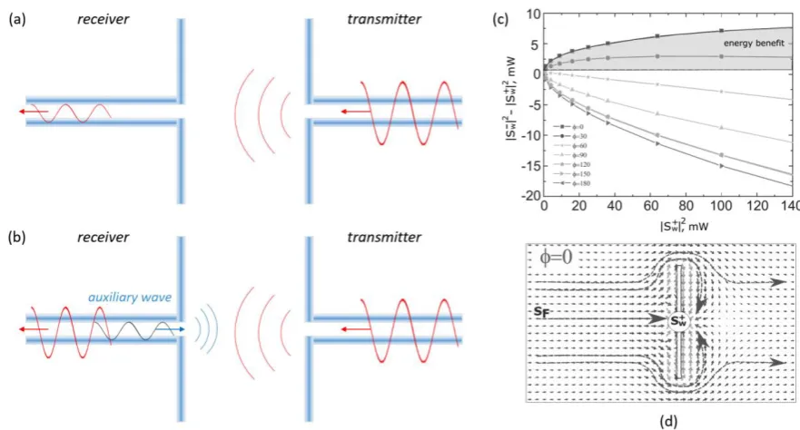
Figure 3. (a) Traditional WPT system consisting of transmitter antenna (right) and receiver antenna
130
(left). (b) Coherently enhanced wireless power transfer system with the receiver antenna driven
131
coherently by an auxiliary wave (shown in blue). (c) Net extracted energy as a function of the
132
auxiliary signal intensity for different relative phase values. Filled area indicates the region of energy
133
benefit, where the coherently assisted energy balance exceeds that for
s
w0
+=
. (d) Poynting vector
134
distribution around the antenna with the auxiliary signal
s
w +In our recent paper we have shown that the same principle that underlies the operation of a CPA
136
can be employed for improving the efficiency of WPT[22]. More specific, we have shown that there
137
is a possibility to improve the receiving efficiency of an antenna by coherent excitation of the
138
outcoupling waveguide with a backward propagating guided mode with specific properties, Figure
139
1(a). Figures 3(a) and (b) demonstrate this idea. Figure 3(a) shows the traditional WPT system
140
consisting of transmitter antenna (right) and receiver antenna (left). Next, we assume that the receiver
141
antenna is driven coherently by an auxiliary wave (shown in blue), Figure 3(b). We have shown that
142
the analysis of this system can be performed in the framework of the temporal coupled mode theory
143
(TCMT)[31–33]. This analysis assumes that the receiving antenna has a single mode with the real
144
eigenfrequency
0 and the mode amplitudea
, normalized such that 2| |
a
is the energy of the145
mode. The dipole antenna couples to the waveguide and free space radiation with the coupling
146
constants
=
{
w,
f}
. The excited antenna mode can decay to both channels with the total147
dumping rate,
1/
=
1/
w+
1/
f. Next, the antenna mode is excited by is the vector of input148
amplitudes
s
+ consisting of the field of the transceivers
f and the auxiliary field of coherent149
excitation
s
w+. The results this analysis gives us the following formula for the amplitude of the150
received field (
s
w−, extracted field)[22]151
w w f f
w w w
0
(
) 1/
s
s
s
s
i
+
−
= − +
++
−
+
. (2)152
The typical results that this equation yields for the net extracted energy are shown in Figure 3(c). The
153
area where the net extracted energy exceeds that for
s
w+=
0
(filled area) corresponds to the energy154
benefit. In these regimes, the antenna revives more energy from the transceiver than it does without
155
coherent excitation even after subtraction of this additional energy. Interesting that in such a regime
156
of positive net extracted energy the Poynting vector distribution around the antenna demonstrates
157
many flow lines ending by the dipole antenna, Figure 3(d). Otherwise, when the relative phase
158
between
s
w +and
s
f is 180 deg., there are a few of Poynting vector lines flowing into the antenna159
that operates in the radiation regime (radiates more than receives).
160
In a practical WPT device, the amplitude and phase of the additional coherent signal can be
161
controlled in real time to adjust the antenna as a function of changes in the environment, temperature
162
changes in the load, and distance of the transmitter.
163
Usually, small antennas like dipole electric or magnetic source possess weak directivity close to that
165
of a point dipole (~1.5)[34]. Here, the directivity parameter is defines as
D
=
4 max[ ( , )] /
p
P
tot166
, where
P
tot is the total radiated power andp
( , )
is the power density of radiation in the167
direction
( , )
. Typical directive antennas such as Yagi-Uda, lens antennas, refractive antennas168
rely on wave propagation/refraction and hence have dimensions much larger than the operation
169
wavelength,
l
?
0. However, as was mentioned in the introduction, there are many application170
areas where electrically small antennas (
l
0) yet very directive are required. This caused intensive171
research on electrically small radiating systems whose directivity exceeds significantly that of a
172
dipole. Such radiative systems were called superdirective[14–21]. Superdirectivity regime is of a
173
particular interest for space communications and radio astronomy. Moreover, achieving high
174
radiation directivity is also important for actively studied optical nanoantennas[35–37].
175
First attempts to achieve superdirectivity regime have been made in the microwave frequency
176
range where it has been demonstrated that antenna arrays can work in this regime in a very narrow
177
frequency range for a sophisticated system of phase shifters[14,16,34,38–40]. Physically, operation
178
principles of superdirective antennas rely on creating rapidly spatially oscillating currents in a
179
subwavelength area, which leads to excitation of higher multipoles[14,21]. Coherent interference of
180
field radiated from all phased dipole or, more general, multipoles leads to the formation of a narrow
181
lobe of power pattern. The antenna becomes directive despite its subwavelength volume. Later, the
182
appearance of the concept of metamaterials[41] – artificially engineered materials with
183
electromagnetic properties at will – caused a new research interest in electrically small directive
184
antennas[42–45].
185
Recent studies on high-index dielectric antennas made of resonators possessing both resonant
186
electric and magnetic responses made it feasible to invent new efficient antennas in
187
microwave[21,46,47] and optics[20,48–52]. It was shown that such subwavelength high-index
188
(usually
n
4
) dielectric spherical resonators possess electric and magnetic Mie189
resonances[21,46,47,53,54], which can be utilized for antenna designing. Although, so-called
190
dielectric resonator antennas are known for decades[55,56], in these studies the critical role of the
191
magnetic Mie resonance has been uncovered first in optics[8,57–59] and later in microwaves[46] and
192
THz due to the scalability of the Maxwell’s equations.
193
A very well-known system of electric and magnetic dipoles radiating coherently with the same
194
phase is called Huygens source[1,60,61]. In result, this source consisting of two multipoles exhibit
195
nearly twice higher directivity than that of a single electric dipole. It has been demonstrated, both in
196
optics and microwaves, that a simple high-index dielectric resonator (spherical or cylindrical) can
197
excited in a system, the directivity of this system can be much greater. In the same time, the size of
199
this dielectric antenna may be sufficiently subwavelength simply because of its high refractive index.
200
This idea has been suggested and realized in our recent works[10,20,21].
201
202
Figure 4. Superdirective dielectric antenna. (a),(b) Photos of the realized antenna. The antenna
203
consists of a dielectric spherical resonator of size ~
0/ 2.5
with a small notch and a short dipole204
source placed inside the notch (b). The dipole fed by a coaxial cable. (c) Results of numerical
205
simulations of the antenna’s directivity and radiation efficiency. (d), (e) Results of experimental
206
realization in an anechoic chamber of the superdirectivity effect (d) and the beam steering effect (e)
207
and their comparison with numerical simulation results.
208
Our approach to superdirective emission is based on making a small notch on a subwavelength
209
high-refractive index spherical dielectric resonator supporting electric and magnetic Mie resonances
210
and placing a dipole source inside this notch, Figures 4(a),(b). This notch breaks the symmetry and
211
increases the contribution of higher-order multipoles[21,23]. The realized antenna consists of a
212
dielectric spherical resonator of size ~
0/ 2.5
and operates at ~17 GHz. As a material of the213
resonator was MgO-TiO2 ceramic spheres characterized at microwaves by permittivity of ~16 and
214
small loss tangent. This spherical resonator made of MgO-TiO2 with the radius 5 mm exhibits lowest
215
Mie resonance at the frequency of ~14 GHz. The radius of the semi-spherical notch was 2 mm, the
216
length of the dipole source was 1.5 mm. In principle, the notched antenna can be formed from a
217
variety of semiconductor materials and can have various shapes – spherical, ellipsoidal, cubic or
218
conical. The dipole fed by a coaxial cable, Figure 4(a). Figure 4(c) shows the results of numerical
219
for such small antenna. This analysis and the analysis of the effective antenna aperture clearly
221
demonstrates that the antenna operates in the superdirectivity regime. The power pattern of this
222
antenna has been measured in an anechoic chamber and the results are presented in Figures 4(d), (e)
223
on the left panel. We see that these results are in a good agreement with the numerical simulations.
224
Remarkably, this antenna exhibits so-called beam steering effect preserving the superdirectivity
225
regime when the dipole source experiences a small shift to the left/right, Figure 4(e).
226
227
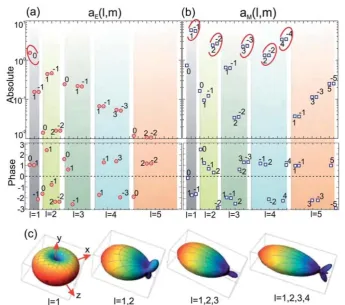
Figure 5. Magnitude (upper row) and phase (lower row) of the most contributing (a) electric and (b)
228
magnetic multipole moments. Multipole coefficients providing the largest contribution to the
229
antenna directivity are highlighted by red circles. (c) Dependence of the radiation pattern of dielectric
230
superdirective antenna on the number of considered multipoles (the dipole source is oriented along
231
the z-axis).
232
Coherent nature of the superdirectivity effect in this dielectric antenna can be revealed by
233
multipole decomposition technique, Figure 5, which consists in following. First, we use numerical
234
simulation to calculate the internal electric and magnetic field distributions. Next, knowing these
235
fields one can calculate the distributions of densities of (bound) carriers
=
1/ (4 )div
E
and236
currents
j
=
c
/ (4 ) rot
(
H
+
ik
E
)
. Finally, using these sources one can calculate the spherical237
harmonic electric and magnetic coefficients
a l m
E( , )
anda
M( , )
l m
, which characterize the238
( )
2
* 3
4
( , )
(
)
(
)
(
1)
E lm l l
k
ik
a l m
Y
rj kr
j kr d r
r
c
i l l
=
+
+
r j
, (3.1)240
2
* 3
4
( , )
div
(
)
(
1)
M lm l
k
a
l m
Y
j kr d r
c
i l l
=
+
r j
, (3.2)
241
where
Y
lm are spherical harmonics of order(
l
0, 0 |
m
|
l
)
,c
is the light velocity, and242
0
2 /
k
=
.243
Figures 5(a),(b) demonstrate the results of the multipole decomposition of the antenna in the
244
superdirective regime. Here, the magnitude (upper row) and phase (lower row) of the most
245
contributing electric (a) and magnetic (b) multipole moments are presented. Multipole coefficients
246
providing the largest contribution to the antenna directivity are highlighted by red circles. We see
247
that despite the small antenna size, it supports multipoles of high order, including electric and
248
magnetic dipole (
l
=
1
), magnetic quadrupole (l
=
2
), octupole (l
=
3
) and so on.249
We have also demonstrated that this superdirectivity regime is accompanied by a significant
250
increase of the effective near field zone of the antenna compared to that of a point dipole for which
251
the near zone radius is ~
0/ 2
[23].252
The results of multipole decomposition allow us to retrieve the power pattern on the antenna
253
and study the role of each multipole to the superdirectivity regime formation. Figure 5(c)
254
demonstrates the dependence of the radiation pattern of the dielectric superdirective antenna on the
255
number of considered multipoles (the dipole source is oriented along the z-axis). This result shows
256
that the directivity grows as higher order multipole terms are added to the response. We see that the
257
coherent emission from many high-order multipoles is crucial for the superdirectivity formation.
258
5. Conclusions
259
Both types of antenna discussed here, coherently driven and superdirective all-dielectric can be
260
utilized in modern intelligent antenna systems in not only radio and microwaves but also in optics.
261
This paper has been dedicated to the analysis of our recent works in this area. We have shown that
262
the concept of coherently enhanced WPT allows improvement of the antenna receiving efficiency by
263
coherent excitation of the outcoupling waveguide with a backward propagating guided mode with
264
a specific amplitude and phase. Antennas with the superdirectivity effect can increase the WPT
265
systems performance in another way, through tailoring of radiation diagram via engineering antenna
266
multipoles excitation and interference of their radiation. We have demonstrated a way to achieving
267
the superdirectivity effect via higher-order multipoles excitation in a subwavelength high-index
268
spherical dielectric resonator supporting electric and magnetic Mie multipoles.
269
References
271
1. C. A. Balanis Antenna theory: analysis and design; New York ; Brisbane : J. Wiley, 1997; ISBN
272
9781118585733.
273
2. Handbook of Microstrip Antennas, Volume 1; James, J. R., Hall, P. S., Eds.; IET: The Institution of
274
Engineering and Technology, Michael Faraday House, Six Hills Way, Stevenage SG1 2AY, UK, 1989;
275
ISBN 9780863417597.
276
3. Rahmat-Samii, Y. Reflector Antennas. In Antenna Handbook; Springer US: Boston, MA, 1988; pp. 949–
277
1072.
278
4. Kwok Wa Leung; Eng Hock Lim; Xiao Sheng Fang Dielectric Resonator Antennas: From the Basic to the
279
Aesthetic. Proc. IEEE2012, 100, 2181–2193, doi:10.1109/jproc.2012.2187872.
280
5. Yaduvanshi, R. S.; Parthasarathy, H. Rectangular Dielectric Resonator Antennas; Springer India: New
281
Delhi, 2016; ISBN 978-81-322-2499-0.
282
6. Novotny, L.; Van Hulst, N. Antennas for light. Nat. Photonics 2011, 5, 83–90,
283
doi:10.1038/nphoton.2010.237.
284
7. Agio, M.; Alù, A. Optical antennas. Opt. Antennas 2011, 9781107014, 1–455,
285
doi:10.1017/CBO9781139013475.
286
8. Krasnok, A. E.; Miroshnichenko, A. E.; Belov, P. A.; Kivshar, Y. S. All-dielectric optical nanoantennas.
287
Opt. Express2012, 20, 20599, doi:10.1364/OE.20.020599.
288
9. Krasnok, A. E.; Maksymov, I. S.; Denisyuk, A. I.; Belov, P. A.; Miroshnichenko, A. E.; Simovskii, C. R.;
289
Kivshar, Y. S. Optical nanoantennas. Uspekhi Fiz. Nauk 2013, 183, 561–589,
290
doi:10.3367/UFNr.0183.201306a.0561.
291
10. Krasnok, A. E.; Maloshtan, A.; Chigrin, D. N.; Kivshar, Y. S.; Belov, P. A. Enhanced emission extraction
292
and selective excitation of NV centers with all-dielectric nanoantennas. Laser Photonics Rev.2015, 9, 385–
293
391, doi:10.1002/lpor.201400453.
294
11. Kurs, A.; Karalis, A.; Moffatt, R.; Joannopoulos, J. D.; Fisher, P.; Soljacic, M. Wireless Power Transfer via
295
Strongly Coupled Magnetic Resonances. Science (80-. ).2007, 317, 83–86, doi:10.1126/science.1143254.
296
12. Song, M.; Belov, P.; Kapitanova, P. Wireless power transfer inspired by the modern trends in
297
electromagnetics. Appl. Phys. Rev.2017, 4, 021102, doi:10.1063/1.4981396.
298
13. Song, M.; Belov, P.; Kapitanova, P. Wireless power transfer inspired by the modern trends in
299
electromagnetics. Appl. Phys. Rev.2017, 4, doi:10.1063/1.4981396.
300
14. Hansen, R. C. Electrically Small, Superdirective, and Superconducting Antennas; John Wiley & Sons, Inc.:
301
Hoboken, NJ, USA, 2006; ISBN 9780470041048.
302
15. Di Francia, G. T. Super-gain antennas and optical resolving power. Nuovo Cim. 1952, 9, 426–438,
303
doi:10.1007/BF02903413.
304
16. Wong, A. M. H.; Eleftheriades, G. V. Adaptation of Schelkunoff’s Superdirective Antenna Theory for the
305
Realization of Superoscillatory Antenna Arrays. IEEE Antennas Wirel. Propag. Lett. 2010, 9, 315–318,
306
doi:10.1109/LAWP.2010.2047710.
307
17. Liu, Y.; Deng, W.; Xu, R. A design of superdirective endfire array in HF band. 2004 Asia-Pacific Radio Sci.
308
Conf. - Proc.2004, 74–77.
309
18. Lugo, J. M.; Goes, J. D. A.; Louzir, A.; Minard, P.; Tong, D. L. H.; Person, C. Design , Optimization and
310
Characterization of a Superdirective Antenna Array. 2013, 1, 3609–3612.
311
19. Altshuler, E. E.; O’Donnell, T. H.; Yaghjian, A. D.; Best, S. R. A monopole superdirective array. IEEE
312
20. Krasnok, A. E.; Simovski, C. R.; Belov, P. A.; Kivshar, Y. S. Superdirective dielectric nanoantennas.
314
Nanoscale2014, 6, doi:10.1039/c4nr01231c.
315
21. Krasnok, A. E.; Filonov, D. S.; Simovski, C. R.; Kivshar, Y. S.; Belov, P. A. Experimental demonstration
316
of superdirective dielectric antenna. Appl. Phys. Lett.2014, 104, doi:10.1063/1.4869817.
317
22. Krasnok, A.; Baranov, D. G.; Generalov, A.; Li, S.; Alù, A. Coherently Enhanced Wireless Power Transfer.
318
Phys. Rev. Lett.2018, 120, 143901, doi:10.1103/PhysRevLett.120.143901.
319
23. Krasnok, A. E.; Simovski, C. R.; Belov, P. A.; Kivshar, Y. S. Superdirective dielectric nanoantennas.
320
Nanoscale2014, 6, 7354–7361, doi:10.1039/c4nr01231c.
321
24. Chong, Y. D.; Ge, L.; Cao, H.; Stone, A. D. Coherent Perfect Absorbers: Time-Reversed Lasers. Phys. Rev.
322
Lett.2010, 105, 053901, doi:10.1103/PhysRevLett.105.053901.
323
25. Wan, W.; Chong, Y.; Ge, L.; Noh, H.; Stone, A. D.; Cao, H. Time-reversed lasing and interferometric
324
control of absorption. Science (80-. ).2011, 331, 889–892, doi:10.1126/science.1200735.
325
26. Zhang, J.; MacDonald, K. F.; Zheludev, N. I. Controlling light-with-light without nonlinearity. Light Sci.
326
Appl.2012, 1, e18, doi:10.1038/lsa.2012.18.
327
27. Baranov, D. G.; Krasnok, A.; Shegai, T.; Alù, A.; Chong, Y. Coherent perfect absorbers: Linear control of
328
light with light. Nat. Rev. Mater.2017, 2, 17064, doi:10.1038/natrevmats.2017.64.
329
28. Pichler, K.; Kühmayer, M.; Böhm, J.; Brandstötter, A.; Ambichl, P.; Kuhl, U.; Rotter, S. Random
anti-330
lasing through coherent perfect absorption in a disordered medium. Nature 2019, 567, 351–355,
331
doi:10.1038/s41586-019-0971-3.
332
29. Potton, R. J. Reciprocity in optics. Reports Prog. Phys.2004, 67, 717–754, doi:10.1088/0034-4885/67/5/R03.
333
30. Baldacci, L.; Zanotto, S.; Biasiol, G.; Sorba, L.; Tredicucci, A. Interferometric control of absorption in thin
334
plasmonic metamaterials: general two port theory and broadband operation. Opt. Express2015, 23, 9202,
335
doi:10.1364/OE.23.009202.
336
31. Wang, K. X.; Yu, Z.; Sandhu, S.; Fan, S. Fundamental bounds on decay rates in asymmetric single-mode
337
optical resonators. Opt. Lett.2013, 38, 100, doi:10.1364/OL.38.000100.
338
32. Fan, S.; Suh, W.; Joannopoulos, J. D. Temporal coupled-mode theory for the Fano resonance in optical
339
resonators. J. Opt. Soc. Am. A2003, 20, 569, doi:10.1364/JOSAA.20.000569.
340
33. Haus, H. Waves and Fields in Optoelectronics; Prentice Hall: Englewood Cliffs, 1984;
341
34. Balanis, C. A. Antenna Theory: A Review. Proc. IEEE1992, 80, 7–23, doi:10.1109/5.119564.
342
35. Alù, A.; Engheta, N. Wireless at the nanoscale: Optical interconnects using matched nanoantennas. Phys.
343
Rev. Lett.2010, 104, 213902, doi:10.1103/PhysRevLett.104.213902.
344
36. Ludwig, A.; Sarris, C. D.; Eleftheriades, G. V. Metascreen-based superdirective antenna in the optical
345
frequency regime. Phys. Rev. Lett.2012, 109, 223901, doi:10.1103/PhysRevLett.109.223901.
346
37. Monticone, F.; Argyropoulos, C.; Alù, A. Optical antennas: Controlling electromagnetic scattering,
347
radiation, and emission at the nanoscale. IEEE Antennas Propag. Mag. 2017, 59, 43–61,
348
doi:10.1109/MAP.2017.2752721.
349
38. Skigin, D. C.; Veremey, V. V.; Mittra, R. Superdirective radiation from finite gratings of rectangular
350
grooves. IEEE Trans. Antennas Propag.1999, 47, 376–383, doi:10.1109/8.761078.
351
39. Kim, O. S.; Pivnenko, S.; Breinbjerg, O. Superdirective magnetic dipole array as a first-order probe for
352
spherical near-field antenna measurements. IEEE Trans. Antennas Propag. 2012, 60, 4670–4676,
353
doi:10.1109/TAP.2012.2207363.
354
40. Veremey, V. Superdirective Antennas with Passive Reflectors. IEEE Antennas Propag. Mag.1995, 37, 16–
355
41. Monticone, F.; Alu, A. Metamaterial, plasmonic and nanophotonic devices. Reports Prog. Phys.2017, 80,
357
036401, doi:10.1088/1361-6633/aa518f.
358
42. Alu, A.; Engheta, N. Enhanced directivity from subwavelength infrared/optical nano-antennas loaded
359
with plasmonic materials or metamaterials. IEEE Trans. Antennas Propag. 2007, 55, 3027–3039,
360
doi:10.1109/TAP.2007.908368.
361
43. Shamonina, E.; Solymar, L. Superdirectivity by virtue of coupling between meta-atoms. 2013 7th Int.
362
Congr. Adv. Electromagn. Mater. Microwaves Opt. METAMATERIALS 2013 2013, 2, 97–99,
363
doi:10.1109/MetaMaterials.2013.6808965.
364
44. Ourir, A.; Burokur, S. N.; Yahiaoui, R.; de Lustrac, A. Directive metamaterial-based subwavelength
365
resonant cavity antennas - Applications for beam steering. Comptes Rendus Phys. 2009, 10, 414–422,
366
doi:10.1016/j.crhy.2009.01.004.
367
45. Sievenpiper, D.; Dawson, D. C.; Jacob, M. M.; Kanar, T.; Kim, S.; Long, J.; Quarfoth, R. G. Experimental
368
Validation of Performance Limits and Design Guidelines for Small Antennas. IEEE Trans. Antennas
369
Propag.2012, 60, 8–19, doi:Doi 10.1109/Tap.2011.2167938.
370
46. Belov, P. A.; Kapitanova, P. V.; Slobozhanyuk, A. P.; Krasnok, A. E.; Filonov, D. S.; Nenasheva, E. A.;
371
Kivshar, Y. S. Experimental verification of the concept of all-dielectric nanoantennas. Appl. Phys. Lett.
372
2012, 100, 201113, doi:10.1063/1.4719209.
373
47. Krasnok, A.; Glybovski, S.; Petrov, M.; Makarov, S.; Savelev, R.; Belov, P.; Simovski, C.; Kivshar, Y.
374
Demonstration of the enhanced Purcell factor in all-dielectric structures. Appl. Phys. Lett. 2016, 108,
375
211105, doi:10.1063/1.4952740.
376
48. Krasnok, A. E.; Miroshnichenko, A. E.; Belov, P. A.; Kivshar, Y. S. Huygens optical elements and Yagi—
377
Uda nanoantennas based on dielectric nanoparticles. JETP Lett. 2011, 94, 593–598,
378
doi:10.1134/s0021364011200070.
379
49. Krasnok, A. E.; Slobozhanyuk, A. P.; Simovski, C. R.; Tretyakov, S. A.; Poddubny, A. N.;
380
Miroshnichenko, A. E.; Kivshar, Y. S.; Belov, P. A. An antenna model for the Purcell effect. Sci. Rep.2015,
381
5, 12956, doi:10.1038/srep12956.
382
50. Li, S. V.; Baranov, D. G.; Krasnok, A. E.; Belov, P. A. All-dielectric nanoantennas for unidirectional
383
excitation of electromagnetic guided modes. Appl. Phys. Lett.2015, 107, doi:10.1063/1.4934757.
384
51. Chattaraj, S.; Madhukar, A. Multifunctional all-dielectric nano-optical systems using collective
385
multipole Mie resonances: toward on-chip integrated nanophotonics. J. Opt. Soc. Am. B2016, 33, 2414,
386
doi:10.1364/JOSAB.33.002414.
387
52. Mahmoud, K. R.; Hussein, M.; Hameed, M. F. O.; Obayya, S. S. A. Super directive Yagi–Uda
388
nanoantennas with an ellipsoid reflector for optimal radiation emission. J. Opt. Soc. Am. B2017, 34, 2041,
389
doi:10.1364/josab.34.002041.
390
53. Filonov, D. S.; Slobozhanyuk, A. P.; Krasnok, A. E.; Belov, P. A.; Nenasheva, E. A.; Hopkins, B.;
391
Miroshnichenko, A. E.; Kivshar, Y. S. Near-field mapping of Fano resonances in all-dielectric oligomers.
392
Appl. Phys. Lett.2014, 104, 021104, doi:10.1063/1.4858969.
393
54. Rybin, M. V.; Kapitanova, P. V.; Filonov, D. S.; Slobozhanyuk, A. P.; Belov, P. A.; Kivshar, Y. S.; Limonov,
394
M. F. Fano resonances in antennas: General control over radiation patterns. Phys. Rev. B - Condens. Matter
395
Mater. Phys.2013, 88, 1–8, doi:10.1103/PhysRevB.88.205106.
396
55. Mongia, R. K.; Ittipiboon, A. Theoretical and experimental investigations on rectangular dielectric
397
resonator antennas. IEEE Trans. Antennas Propag.1997, 45, 1348–1356, doi:10.1109/8.623123.
398
resonant frequency and bandwidth. Int. J. Microw. Millimeter‐Wave Comput. Eng. 1994, 4, 230–247,
400
doi:10.1002/mmce.4570040304.
401
57. Evlyukhin, A. B.; Reinhardt, C.; Seidel, A.; Luk’Yanchuk, B. S.; Chichkov, B. N. Optical response features
402
of Si-nanoparticle arrays. Phys. Rev. B - Condens. Matter Mater. Phys. 2010, 82, 45404,
403
doi:10.1103/PhysRevB.82.045404.
404
58. Evlyukhin, A. B.; Novikov, S. M.; Zywietz, U.; Eriksen, R. L.; Reinhardt, C.; Bozhevolnyi, S. I.; Chichkov,
405
B. N. Demonstration of magnetic dipole resonances of dielectric nanospheres in the visible region. Nano
406
Lett.2012, 12, 3749–3755, doi:10.1021/nl301594s.
407
59. Kuznetsov, A. I.; Miroshnichenko, A. E.; Fu, Y. H.; Zhang, J.; Lukyanchukl, B. Magnetic light. Sci. Rep.
408
2012, 2, 492, doi:10.1038/srep00492.
409
60. Jin, P.; Ziolkowski, R. W. Metamaterial-Inspired, Electrically Small Huygens Sources. IEEE Antennas
410
Wirel. Propag. Lett.2010, 9, 501–505, doi:10.1109/LAWP.2010.2051311.
411
61. Ziolkowski, R. W. Low profile, broadside radiating, electrically small huygens source antennas. IEEE
412
Access2015, 3, 2644–2651, doi:10.1109/ACCESS.2015.2505726.
413
62. Jackson, J. D. Classical Electrodynamics; 3rd ed.; John Wiley and Sons Inc., 1998;