Application of Multiple Antenna Channel Coded
OFDM Schemes in Power Line Communication
Oludare Sokoya,
Member, IAENG
Abstract—In this paper the performance of multiple an-tenna channel coded orthogonal frequency division multiplexing (OFDM) schemes are examined in a power line communication channel. The power line channel is modeled using Zimmermann model. The bit error rate curve of the mutiple antenna channel coded-OFDM schemes in a power line channel is compared with uncoded OFDM. For the power line channel, increased performance in terms of coding gain and diversity advantage is obtained for when multiple antenna channel coded OFDM schemes are used.
Index Terms—Mutiple Antenna Channel Codes, PLC, OFDM, Multipath Fading, Impilse noise.
I. INTRODUCTION
W
ITH the spread of Smart Grid concepts, Powerline Communication (PLC) which has been initially used for voice transmission has become one imptortance option for the data communications infrastructure [1]. PLC has become an attaractive option for conventional wired and wireless indoor transmission due to the development of robust mod-ulation, channel coding and digital signal procession tech-nologies. PLC offer a potentially convenient and inexpesive solution because of the unique fact that no new wires are needed. Existing power lines, which are originally installed in the rooms for power supply are used for communication. PLC is an altenative to other ”last mile” technologies, such as Digital Subscriber Line (DSL) [2], Wireless Local Loop (WLL), Wireless Local Area Network (WLAN), etc. Many of the available PLC systems provides a maximum data rate of more than several Mbps [3]. Nevertheless, powerline grid can be characterised as a rather hostile medium for data transmission as it was initially designed for the distribution of electrical power in frequency of 50–60Hz. As a result, the PLC channel encounters some technical problems, such as impedance variations and mismatches, various forms of noises (Gaussian and impulsive noise) and narrowband in-terference, multipath propagation, high attenuation and other forms of channel impairments.The transmission environment in PLC seems to be much worse than in wireless communications, which necesitate the use of advanced physical layer techniques in the PLC environment in order to benefit from its possible advantages. One way of combating the technical problems of PLC, is to employ specially designed multiple antenna channel coded OFDM with PLC in order to achieve some of the objective of a reliable communication system i.e. low error rate, low received Signal to Noise Ratio (SNR), perform well
Manuscript received July 20, 2017; revised August 2, 2017. This work was supported in part by the Department of Electronic Engineering Durban University of Technology, South Africa.
O. Sokoya is with the Department of Electronic Engineering, Dur-ban University of Technology, DurDur-ban, KZN, 4000 South Africa e-mail:[email protected].
in mutipath and fading conditions, spectral efficiency and cost effective in its implementation.
Multiple antenna channel coded OFDM schemes i.e. Time Block Coded-OFDM (STBC-OFDM) [4], Space-Time Trellis Coded-OFDM (STTC-OFDM) [5] and Super-Orthogonal Space-Time Trellis Coded-OFDM (SOSTTC-OFDM) [6] are bandwidth efficient multiple antenna schemes that can increase system capacity through antenna diversity. These codes use the combination of conventional channel coding design criteria, modulation techniques and multiple antenna diversity techniques in their design. Multiple antenna channel coding schemes give a better error rate performance when compared with an uncoded scheme.
In this paper, the performance of multiple antenna chan-nel codes in a PLC scenario is studied . The error rate performance of majorly known multiple antenna channel coded OFDM schemes i.e. STBC-OFDM, STTC-OFDM and SOSTTC-OFDM is studied in powerline environment. The outline of the paper is as follows. In section II, the power line channel models are briefly discussed. The design structure of the various multiple antenna channel codes are given in section III. The system structure is delineated in section IV. Simulation results are presented in section V, while conclusion remark are drawn in section VI
II. POWERLINECHANNELMODELING
The design of a good communication systems begins with a thorough understanding of the communication channel. Many researchers have proposed diferent PLC channel mod-els and so far there is not a universally accepteble model. This is due to some characteristics of the powerline channel that makes it difficult to model. Technical problems of the powerline channel relate to:
• The frequency–varying and time–varying response.
• Transfer function with dependence of location, topology
network, and connected load.
• Different types of noise – Impulse noise, background
noise, narrowband noise and power wave.
In [7], PLC channel modeling research works were cate-gorised into the following areas:
• Noise Modeling – The power spectral density of the
noise is very much reliant on location and time. Also, measurement shows that it consists of colored back-ground noise, periodic impulsive noise, narrowband noise and asynchronous impulsive noise [8]. In order to model the additive noise, statistical parameters are extracted after many measurements, resulting in random variables with specific probability density function.
models. These tools allow verifying the reliability and accuracy of the models, and sometimes having a user friendly graphic/machine interface.
• Transfer function modeling – Transfer function can be
modeled either using an emperical approach (i.e. mod-eling parameters are determined from measurements) or a deterministic approach (i.e. modeling parameters are obtained from a theoretical basis). The emperical approach is easy to implement and computationally efficient but susceptible to measurement errors while the deterministic approach is computationally more in-tensive than the emperical approach. The advantage of the deterministic approach is that changes to the transfer function can be predicted [10]. In this paper, deterministic approach is adopted.
Any modeling approach for the transfer function can be both time and frequency dependent and also dependent on the location of the transmitter and the receiver in the specific powerline infrastructure.
As mentioned earlier, a PLC channel can be characterised with both impulsive noise and multipath fading, as a result of the multiple signal reflections caused by power line impedance mismatch. The most suitable model for the im-pulsive noise is the Middleton Class A model [11], which probability density function is defined as:
PX(x) =
∞ X
m=0
e−AA
m
m! 1
p
2πσ2
m
e− x
2
2σ2
m
, (1)
σm2 = σ2m/A+τ
1 +τ , (2)
whereσ2=σ2
G+σI2(σ2Gis the Gaussian noise variance and
σ2
I is the impulse noise variance), τ = σ2G σ2 I
, and A is the impulse index. Also, in a PLC channel, there are two types of channel models; deterministic-one like Zimmermann model [12], and statististical-one like Galli model [13]. The transfer function of Zimmermann model at the jth antenna path is expressed as:
Hj(f) = L
X
l=1
Hj,l(f), (3)
Hj,l(f) = gj,l.e−(α0+α1.f u)d
j,l.ej2πf(dj,l/vp), (4)
whereLis the number of fading paths per antenna path.α0,
α1anduare the power line cable parameters, and|gj,l| ≤1
is the weighting factor of the jth antenna and thelth fading path. dj,l/vp is equiivalent to the corresponding path delay
Tj,l (where dj,l represent its length):
Tj,l =
dj,l. √
r
c0
= dj,l vp
, (5)
whereris the non insulation dielectric constant of the cable andc0 is the speed of light. The frequency selective fading
channel transfer function in (3) can be translated into the OFDM domain by approximating it as follows:
Hj(f)|f=fc+k∆f ∼= Hj(k) = L
X
l=1
Hj,l(k), (6)
where fc is the carrier frequency, ∆f is the subcarrier spacing, andk(= 0,1, ..., N−1,whereN is the number of subcarriers) in the frequency index.
III. MULTIPLEANTENNACHANNELCODES
Multiple antenna channel codes can be combined with OFDM to produce a system that can achieve spectra effi-ciency and increase throughput in a network. These codes are bandwidth efficient and do not sacrifice diversity over a the channel. Brief description of these channel codes is given in the following sections.
A. Space-Time Block Code
Alamouti first presented a transmit diversity technique, for two transmit antennas, with a simplified decoding algorithm [14]. This scheme was later called STBC in [15]. Based on these later works, the Alamouti codes were extended to more than two transmit antennas using the theory of orthogonal design. The theory of orthogonal design enables the use of a simple maximum-likelihood decoder that is based on linear combining at the receiver. Based on this theory, two types of STBC can be generated. The first type, real orthogonal design, is based on real constellation such as pulse amplitude modulation, while the second type, complex orthogonal design, is based on complex constellations, e.g. phase-shift keying and quadrature amplitude modulation. The transmission matrix for a two transmit antenna complex orthogonal design is given by:
C =
x1 x2
−x∗2 x∗1
. (7)
B. Space-Time Trellis Code
STTC was invented by Tarokh et al. [16] as a way of combining signal processing with a multiple antenna system to produce a system with an improved gain over the earlier transmit diversity schemes [17]. The STTC proposed in [16] was handcrafted and gives the best compromise in terms of constellation size, data rate, diversity advantage and trellis complexity when compared with other space time trellis coded schemes [17].
The encoder system of an STTC is based on a one-input symbol at a time and a sequence of output symbols, whose length represents the number of transmit antennas.
The trellis diagram for a four-STTC is shown in Figure 1. At each timet , the encoder is in a generic state. The input bit streams to the space-time encoder are divided into groups of two bits,a1a2 . Each group 00, 01, 10 or 11 then selects
one of the four branches originating from the corresponding state. The branches are then mapped for every transmit antenna into one of the four constellation points on the QPSK constellation. The edge labelsy1y2in Figure 1 are associated
with the four transitions from top to bottom and indicate that symbols y1 andy2 are transmitted simultaneously over the
first and second antennas, respectively. The encoder moves to the next state after transmission of the couple of symbols. At the decoder, based on the received estimate and using the maximum likelihood (ML) method, a decoding algorithm is then used to search for the best path. Viterbi algorithm is then used to search for the path with the least decoding metric.
C. Super-Orthogonal Space-Time Trellis Code
00 01 02 03
1 2 1 2 1 2 1 2
y y y y y y y y
10 11 12 13
20 21 22 23
[image:3.595.362.497.49.291.2]30 31 32 33
Fig. 1. Four-state QPSK STTC
SOSTTC was developed [18]. The SOSTTC uses sets of super-orthogonal block codes (SOBC) and set partitioning technique in its construction. The sets of SOBCs are obtained by rotating the original block code by an angleθ. This code gives an improved coding gain and diversity order when compared with other space-time coding schemes, i.e. STTC [16] and STBC [14]. The main idea behind SOSTTC is to consider STBCs as a modulation scheme for multiple trans-mit antennas and assign an STBC with specific constellation symbols to transitions emanating from a state. For a T×Nt STBC, picking a trellis branch emanating from a state is equivalent to transmitting TNtsymbols from theNttransmit antennas in T time intervals. By doing so, it is guaranteed that the diversity of the corresponding STBC is preserved. The SOBC transmission matrix used in the design of SOSTTC for Nt= 2 is given by:
X(x1, x2, θ) =
x1ejθ x2
−x∗2ejθ x∗1
. (8)
In equation (8) xi ∈ ej 2πa´
M represent the M-PSK signal constellation. The angular rotationθ is equivalent to2π´a/M wherea´= 0,1,· · ·,M−1. Despite the angular rotation of the transmitted signal, the matrix elements of equations (8) are still members of the M-PSK constellation and the signal constellation is not expanded. For BPSK signal constellation, θ = 0 or π while for a QPSK signal constellation, θ = 0 or π/2 or π or 3π/2. When θ in equation (8) is zero, the Alamouti code is obtained.
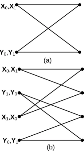
The trellis diagram for a two-state and a four-state SOSTTC scheme is given in Figure 2. In the trellises in Figure 2, each path converging and diverging to a state consists of eight parallel paths. The state labels, i.e.XiandYiare sets of SOBC given in equation (9).
X0 ≡ {(±1,±1,0),(±j,±j,0)}
X1 ≡ {(±1,±j,0),(±j,±1,0)}
Y0 ≡ {(±1,±1, π),(±j,±j, π)}
Y1 ≡ {(±1,±j, π),(±j,±1, π)} (9)
In each set of the SOBC e.g.Xi, eight different block codes are possible. These block codes are obtained by substituting
X
0,
X
1Y
0,
Y
1(a)
Y
1,
Y
0X
1,
X
0Y
0,
Y
1(b)
X
0,
X
1Fig. 2. Two-state (a) and four-state (b) QPSK SOSTTC
the symbol elements {+1,−1, j,−j}, for a QPSK symbol constellation into the orthogonal matrix given in equation (8). The corresponding orthogonal block codes are then transmitted on the trellis branch.
In flat fading channel, multiple antenna channel codes (i.e. STTC, STBC and SOSTTC) exploit the spatial diversity present in the multiple transmit/receiver antennas to produce codes that are effective in combating fading and enhancing the data rate. The maximum diversity gain possible in a flat fading channel is the product of the number of transmit and receive antennas.
Whereas in frequency selective fading channel, mutiple antenna channel codes and OFDM can potentially exploit the multipath diversity possible in the frequency selective fading channel. As a result of the multipath diversity, the maximum diversity possible for the channel codes in an OFDM environment is therefore a product of the number of transmit antennas and receive antennas and the channel impulse response length.
Some of the mutiple antenna channel codes with OFDM that have been introduced in the literature include STTC-OFDM [19], STBC-OFDM [4] and SOSTTC-OFDM [6].
IV. SYSTEMSTRUCTURE
The general layout of the simulation can be seen in the figure 3 below. The data to be transmitted is first coded with
Fig. 3. System Structure
[image:3.595.64.279.56.244.2]examination is Quadrature Phase Shift Keying (QPSK). The signal power for the modulation scheme is normalised to unity. The OFDM modulation scheme is suitable for PLC due to its ability to deal with multipath propagation, intersymbol interference and frequency selective channels. The space-time codes that is used in this study utilizes two emitting points/ antenna and one receving points/ antenna.
The Class A noise is characterised by three parameters, which are impulsive index A, the variace of the AWGN component σg2 and ratio τ. In this paper, A is set to equal to 0.1, σ2g = 10−3W and τ = 0.001. The parameter A determine the ”impulsivement” of Clas A noise (i.e. it is the product of the mean number of impulses per second and the mean length of an impulse in seconds).
V. PERFORMANCEEVALUATION ANDSIMULATION RESULTS
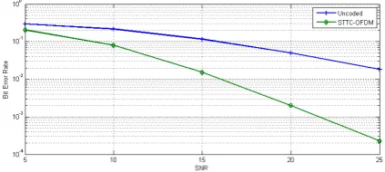
[image:4.595.324.535.58.156.2]For the performance evaluation of the proposed sytems, a simulation was developed in Matlab. The figures presented in this paper were obtained by averaging the results of multiple simulations runs, in order to minimize the statistical errors and assures the validity of the results. The proposed system simulation is shown to demonstrate the bit error rate (BER) performance of the mutiple antenna coded OFDM schemes, i.e., STBC-OFDM, STTC-OFDM and SOSTTC-OFDM in a power line environment. The simulation assumes a PLC multipath fading channel (using the deterministic-one like Zimmermann model [12]) with L = 2, Nt = 2 and Nr = 1 . The total power of the transmitted coded symbol was normalized to unity and a frame length of 256 bits was used at the transmitter.
Fig. 4. BER performance for PLC channel using QPSK STBC-OFDM
Fig. 5. BER performance for PLC channel using QPSK 4-state STTC-OFDM
[image:4.595.64.280.445.541.2]In Figures 4, 5 and 6, the BER performance of mutiple antenna channel coded OFDM schemes and uncoded OFDM with power line channel is given. The figures show that there is a coding gain advantage of the mutiple antenna channel coded OFDM schemes when compared with uncoded OFDM
Fig. 6. BER performance for PLC channel using QPSK 4-state SOTTC-OFDM
in a power line channel. This is evident in the downward shift of the BER curves. In the figures, it is also apparent, based on the slope of the graph, that the mutiple antenna channel coded OFDM schemes in maintains it diversity advantages considering the impulsive nature of the noise component of the power line environment.
VI. CONCLUSION
In this paper the BER performance of mutiple antenna channel coded OFDM schemes, i.e. STBC-OFDM, STTC– OFDM and SOSTTC-OFDM, in a power line environment, is considered. The mutiple antenna channel coded OFDM schemes appear to be quite beneficial in terms of BER performance when compared with uncoded OFDM in this environment. The mutiple antenna channel coded OFDM schemes show an increased coding gain advantage and diversity adavantage . In general this study demonstates that power line environment can profit a lot when mutiple antenna channel coded OFDM schemes are incoporated in its design.
REFERENCES
[1] S. Galli and et al, “For the Grid and Through the Grid: The role of Power Line Communication in the Smart Grid,”Proceedings of IEEE, vol. 99, no. 6, pp. 998–1027, June 2011.
[2] C. Assimakopoulous and et al, “xDSL Techniques for Power Line Communications,”Proceeding of International Symposium on Power-Line Communications and Its Application 2003 (ISPLC 2003), pp. 21–25, March 2003.
[3] W. Liu and et al, “Broadband PLC Access Systems and Field De-velopment in European Power Line Networks,”IEEE Communication Magazine, vol. 41, no. 5, pp. 114–118, May 2003.
[4] G. Bauch, “Space-time block codes versus space-frequency block codes,” inProceedings of the IEEE Vehicular Technology Conference, Seoul, Korea, April 2003, pp. 567–571.
[5] Y. Hong and et. al., “Performance analysis of space-time trellis coded OFDM system,” inProceedings of IEEE Vehicular Technology Conference, vol. 2, Stockholm, Sweden, May 2005, pp. 1176–1180. [6] K. Aksoy and U. Aygolu, “Super-orthogonal space time frequency
trellis coded OFDM,” IET Communication, vol. 1, no. 3, pp. 317– 324, June 2007.
[7] G. Laguna and et al, “Survey on Indoor Power Line Communication Channel Modeling,”Procedings of Electronic, Robotics and Automo-tive Mechanics Conference, pp. 163–167, June 2008.
[8] M. Zimmermann and K. Dostert, “Analysis and modeling of impulsive noise in broad-band powerline communications,”IEEE Transactions on Electromagnetic Compatibility, vol. 44, no. 1, pp. 249–258, Feb 2002.
[9] F. Aalamifar, A. Schlgl, D. Harris, and L. Lampe, “Modelling power line communication using network simulator-3,” in2013 IEEE Global Communications Conference (GLOBECOM), Dec 2013, pp. 2969– 2974.
[10] H. Meng and et al, “Modeling of transfer characteristic for broadband power line communication channel,” IEEE Transaction on Power Delivery, vol. 19, no. 3, pp. 1057–1064, July 2004.
[image:4.595.66.278.589.684.2][12] M. Zimmermann and K. Dostert, “A multipath model for the powerline channel,”IEEE Transactions on Communications, vol. 50, no. 4, pp. 553–559, Apr 2002.
[13] S. Galli, “A simplified model for the indoor power line channel,” in
2009 IEEE International Symposium on Power Line Communications and Its Applications, March 200, pp. 13–19.
[14] S. Alamouti, “Space-time block coding: A simple transmitter diversity technique for wireless communications,”IEEE Journal on Selected Areas in Communication, vol. 16, pp. 1451–1458, October 1998. [15] V. Tarokh, H. Jafarkhani, and A. R. Calderbank, “Space-time block
codes from orthogonal designs,”IEEE Transactions on Information Theory, vol. 45, pp. 1456–1467, July 1999.
[16] ——, “Space-time codes for high data rate wireless communication; Performance analysis and code construction,”IEEE Transactions on Information Theory, vol. 44, no. 2, pp. 744–756, March 1998. [17] N. Seshadri and J. H. Winters, “Two signaling schemes for improving
the error performance of frequency division duplex (FDD) transmis-sion systems using transmit antenna diversity,”International Journal on Wireless Information Networks, vol. 1, no. 1, pp. 49–60, January 1994.
[18] H. Jafarkhani and S. Seshadri, “Super-orthogonal space-time trellis codes,”IEEE Transactions on Information Theory, vol. 49, pp. 937– 950, April 2003.
[19] Y. Hong, J. Choi, and X. Shao, “Performance analysis of space-time trellis coded OFDM over quasi-static frequency selective fading channel,” inProceedings of the 2003 Joint Conference of the Fourth International Conference on Information, Communications and Signal Processing and Fourth Pacific Rim Conference on Multimedia, vol. 3, Singapore, December 2003, pp. 1478–1482.