PAPER
Received 00th January 20xx, Accepted 00th January 20xx
DOI: 10.1039/x0xx00000x
www.rsc.org/
A novel in-situ diffusion strategy to fabricate high performance
cathode for low temperature proton-conducting solid oxide fuel
cells
Jie Hou ab, Lina Miao a, Jianing Hui b, Lei Bi c, Wei Liu a*, John T. S. Irvine b*
Developing new low-cost high-performance cobalt-free cathode materials for low temperatureproton-conducting solid oxide fuel cells (H-SOFC) has been an imperative topic. In response to this challenge, we herein develop a novel in-situ Pr diffusion strategy based on Sm0.2Ce0.8O2-δ-Pr(Pr0.5Ba1.5)Cu3O7-δ (SDC-PBCu, 3:7 wt.%) compound, to achieve a perovskite-related
proton-blocking composite cathode (PBCC) Ce1-xPrxO2-δ-Ba2CeCu3O7.4-Sm2Ba1.33Ce0.67Cu3O9-CuO (PDC-BCC-SBCC-CuO)
for BaZr0.1Ce0.7Y0.2O3-δ-based H-SOFC. The single cell achieves a remarkable performance with the maximum power density
(MPD) of 1000 and 566 mW cm-2, corresponding to the interfacial polarization resistance (R
P) of 0.037 and 0.188 Ω cm2 at
700 and 600 °C, respectively. The XRD results demonstrate that the PBCu phase disappear after the calcination of the mixed SDC-PBCu composite powder at 900 °C, with the formation of four new phases including fluorite structured PDC, orthorhombic layered material BCC, tetragonal perovskite-related SBCC and a small quantity of metallic oxide CuO, being favorable for a superior cathode performance. The ascendant electrochemical performance including the very high MPD and the lower RP obtained here indicate that the quaternary cobalt-free PBCC PDC-BCC-SBCC-CuO is a preferable alternative
for high-performance low-temperature H-SOFC.
1.
Introduction
In the present solid oxide fuel cell (SOFC) research, lowering the SOFC operating temperature to low temperatures (LTs, ≤ 600 °C) accompanied with an advisable cell performance is the primary target 1-3. In virtue of the low activation energy (E
a) and good ionic conductivity, proton-conducting oxides have intriguing potential for high performance low temperature SOFC (HPLT-SOFC) 4-6. In spite of BaCeO
3-based protonic conductors have shown relatively high proton conductivity (10-2 S cm-1 at 600 °C 7), its reaction with CO
2 and H2O hinder the practical application 8-10. To increase the chemical stability of BaCeO
3, one common approach is to partially replace Ce by Zr, and a good component BaZr0.1Ce0.7Y0.2O3-δ (BZCY) exhibiting both sufficient chemical stability and adequate proton conductivity, has been one of the most popular protonic conductors 11-14.
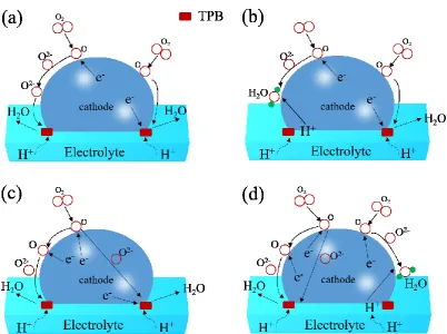
For proton-conducting SOFC (H-SOFC), as a result of the relatively large Ea of oxygen reduction reaction (ORR), the cathode polarization dominates the cell loss when the temperature is reduced 15. A good cathode should possess adequate electrical conductivity, good catalytic activity, fine
chemical compatibility and a compatible expansion coefficient (TEC) with the electrolyte 16, 17. By now, the transfer mode in H-SOFC cathode can be divided into four types. The first type, shown in Fig. 1(a), is a single electronic conductor which can only transport electronic defects. Less attention was paid to this type of cathode because the extremely weak ability to transport oxygen ions (O2-) impedes the ORR. Xie et al 18 used Nd0.7Sr0.3MnO3-δ for BaCe0.4Zr0.3Sn0.1Y0.2O3-δ-based H-SOFC and achieved a poor polarization performance (0.33 Ω cm2at 700 °C). Hou et al. 19 also employed LaNi0.6Fe0.4O3-δ (LNF) cathode for BZCY-based cell and proved it that the electrochemical performance could be greatly improved when compounded with an oxygen ionic conductor La2NiO4+δ (LNO). As shown in Fig. 1(b), for the second type of cathode, the H-SOFC cathode can transport electronic defects and protons (H+) at the same time. This typological cathode material can choose both single mixed protonic and electronic conductors (MPEC) and composite materials composed of an electronic conductor and protonic conducting phase. More attention was paid to the doping of BaCeO3 or BaZrO3-based materials. For example, based on the BZCY electrolyte, BaCe0.5Bi0.5O3-δ 20 and BaCe0.5Fe0.5O3-δ 21 obtained the power output of 321 and 395 mW cm-2 at 700 °C , respectively. To increase the catalytic activity, the Co-doping is taken into account. Duan et al 1 made use of BaCo0.4Fe0.4Zr0.1Y0.1O3-δ as the cathode for BaCe0.7Zr0.1Y0.1Yb0.1O3-δ electrolyte and achieved predominant cell performance. As most single-phase cathode of this type has
a.CAS Key Laboratory of Materials for Energy Conversion & Collaborative
Innovation Center of Suzhou Nano Science and Technology, University of Science and Technology of China, Hefei 230026, PR China. Eamil: [email protected]
b.School of Chemistry, University of St Andrews, KY16 9ST, UK. Eamil:
c.Institute of Materials for Energy and Environment, College of Materials Science
Fig. 1 The transfer mode in H-SOFC cathode.
a relative poor electro-catalytic ability, Zhu et al 22 designed a composite cathode which was made up of BZCY and LNF and achieved superior electrochemical performance with BZCY electrolyte cell. As shown in Fig. 1(c), H-SOFC cathode with the third typological transfer mode can synchronously transport electronic defects and oxygen vacancies, which can also use single mixed ionic and electronic conductors (MIEC), or composite components containing electronic conducting phase and oxygen-ion conductor. The normally used MIEC materials are perovskite, layer-structured perovskite and Ruddlesden-Popper phase, e.g. La0.6Sr0.4CoO3-δ 23, SmBaCuCoO5+δ 24, YBaCuCoO5+x 25 and Pr2-xSrxNiO4+δ 26. Most research was focused on the composite cathode for the superior electrochemical performance with both high electro-catalytic activity and admirable oxygen transfer ability, e.g. Sm0.5Sr0.5Co 3-δ-SDC 27 and Ba0.5Sr0.5FeO3-δ-SDC 28. Differently, the H-SOFC cathode with the forth typological transfer mode allows simultaneous transport oxygen vacancies, electronic defects and protons, which is shown in Fig. 1(d). This kind of materials mostly employ MIEC compounded of protonic conducting phase, e.g. Sm0.5Sr0.5CoO3-δ-BaCe0.8Sm0.2O3-δ29, PrBaCo2O5+δ -BZCY 30, GaBaCoFeO5+δ-BZCY 31 and La0.6Sr0.4Co0.2Fe0.8O3-δ -BaZr0.1Ce0.7Y0.1Yb0.1O3-δ32.
In general, the H-SOFC cathode can be divided into two categories. One category is the proton-blocking cathode (PBC, containing the first and third typological transfer mode) and another category is the proton-conducting cathode (PCC,
including the second and forth typological transfer mode). In the literature, most single-phase cathode materials have weaker transportation ability of oxygen ions for PBC and lower electronic conductivity for PCC than dual-phase composite cathodes. Both the inferior oxygen ion transfer for PBC and the weak electro-catalytic activity for PCC limit the research of the single-phase cathode materials. For H-SOFC composite cathodes, Sun et al 12 have also found it that the PBC La0.7Sr0.3FeO3-δ-SDC (LSF-SDC) revealed higher electro-catalytic ability than PCC LSF-BZCY, which is correlative with water produced at the cathode, occupying the electrochemical reaction sites and lessening the oxygen partial pressure.
In the light of the problems cobalt-containing H-SOFC cathode faced, e.g. high thermal expansion coefficients (TEC), easy reduction, evaporation and the high cost of cobalt element 19, in this assignment, a novel in-situ Pr diffusion strategy to
maintaining a large oxygen vacancy content, contributing to fast oxygen ion diffusion 34, 35. Moreover, the high oxygen ionic conductor PDC and electronical conductor CuO are also helpful for achieving high cathode performance. When coupling SDC with PBCu to form a compound as cathode, it is supposed to have a better cell performance.
2.
Experimental
2.1.
Preparation of powders
PBCu, SDC and BZCY powders were synthesized via a citric acid-nitrate gel combustion process 27, 36. The raw materials for synthesis of PBCu powders were Pr6O11, BaCO3, Cu(NO3)2•3H2O, and Sm2O3, Ce(NO3)3•6H2O were used for synthesizing SDC. BaCO3, Zr(NO3)4•5H2O, Ce(NO3)3•6H2O, Y(NO3)3•6H2O served as the crude materials for BZCY powders. After combustion, the as-prepared ash-like powders were calcined at 900, 600 and 1000 °C for 3 h in air to obtain PBCu, SDC and BZCY powders, respectively.
2.2.
Fabrication of anode-supported single cells
The NiO-BZCY composite powder with a weight ratio of 65:35 for the anode substrate and anode functional layer (AFL) were prepared by the one-step gel combustion process 27, 36. The composite powders were calcined at 1000 °C for 3 h and then 20 wt.% starch was added as pore-creating materials to form sufficient porosity in the anode. The anode supported half cells with a tri-layered structure containing anode, AFL (NiO-BZCY composite powders with no starch) and BZCY electrolyte layer, were fabricated by a co-pressing method 37 and then co-fired at 1400 °C for 5 h.
SDC mixed with PBCu in the weight ratio 3:7 thoroughly together with a 10 wt.% ethylcellulose-terpineol binder was used to prepare SDC-PBCu cathode ink. The ink was then painted onto the dense BZCY electrolyte membrane and fired at 900 °C for 3 h in air to form a porous cathode layer. Ag paste and wire were applied to the cathode as a current collector and the conducting wire, respectively. The effective area of the cathode was 0.237 cm2.
2.3.
Characterization
and
electrochemical
measurements
The single cell was tested in a home-made cell testing system at the temperature range of 450-700 °C. Humidified hydrogen (~3%H2O) at a flow rate of 30 ml min-1 and ambient air were used as the fuel and oxidant, respectively. The water vapor pressure about 0.03 atm was achieved by bubbling H2 through water at about 25 °C. I-V curves of the cells were collected with a DC Electronic Load (ITech Electronics model IT8511) based on a two-probe configuration. The electrochemical impedance spectra were measured under open circuit conditions using an impedance analyzer (CHI604E, Shanghai Chenhua) (0.1-100 kHz, 5 mV as AC amplitude). Ohmic resistance and polarization resistance of the cells under open circuit conditions were determined from the impedance spectra. Phase compositions of SDC-PBCu mixed powders fired at 900 and 950 °C were
identified by X-ray powder diffraction on a PANalytical Empyrean Reflection Diffractometer using CuKα1 radiation, and phase structure of the cobalt-free quaternary PBCC PDC-BCC-SBCC-CuO derived from SDC-PBCu was characterized by high-resolution transmission electron microscope (HRTEM, JEM-2010). The microstructures of the cell components were investigated by a scanning electron microscopy (SEM, JEOL JSM-6700F).
3.
Results and discussion
3.1.
Phase structure and Pr diffusion
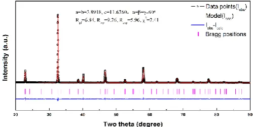
As shown in Fig. 2, rietveld analysis of X-ray powder diffraction data reveals that PBCu calcined at 900 °C exhibits a tetragonal layered perovskite structure with P4/mmm space group symmetry and the lattice constant of a=b=3.8918 Å and c=11.6360 Å. The tick marks below the patterns represent the Bragg positions. The lower blue line represents the difference between the observed and calculated intensities. The quality of the agreement between observed and calculated profiles is estimated by profile factor (Rpf), weighted profile factor (Rwp), expected weighted profile factor (Rexp), and reduced chi-square (χ2). The rietveld refinement converges in a good χ2(=2.41) and the reliable parameters guarantee the reliability of refinements.
Fig. 2 Rietveld refinement plot of PBCu powders using X-ray powder diffraction data
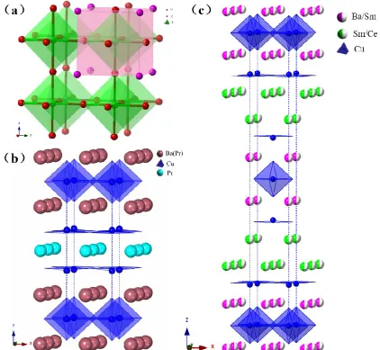
[image:3.595.305.555.378.503.2]perovskites. Then the PBCu could be understood as the single PrO layer alternates with two element
Fig. 3 Structure of (a) normal perovskite (ABO3), (b) tetragonal PBCu and (c) layerd Sm2Ba1.33Ce0.67Cu3O9.
randomly distributed Ba(Pr)O layers, such as
- 2-
- ' 2- - ' 2Ba Pr O CuO Ba Pr O Cu O PrO Cu O, which can be written as Pr(Pr0.5Ba1.5)Cu3O7-δ or Pr(Pr0.25Ba0.75)2Cu3O7-δ. The randomly distributed Pr in the Pr(Ba)O layers could also promote to form the oxygen vacancy defects, which will complement with the large numbers of oxygen vacancy defects in the PrO layers to transfer oxygen ions efficiently in two different dimensional layers. The Pr-O bond is shorter than Ba-O bond, leading to a different chemical force of the PrO layer and Ba(Pr)O layer with CuO6 octahedral, which will compress the PrO layer with the stretch of the Ba(Pr)O layer, resulting in the formation of the tetragonal layered structure 15, 38. Notedly, in virtue of the oxygen deficiency in the PrO layer, the near Cu only has an oxygen 5-fold coordinated scaf5-fold (BO5).
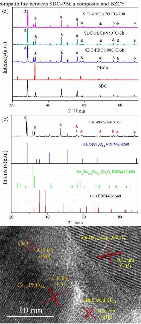
The phases of SDC-PBCu mixed powders calcined at 900, 950 °C for 3 h and 700 °C for 20 h after the treatment at 900 °C were studied by the powder XRD technique which is shown in Fig. 4(a). Indexing of these patterns reveals that SDC has a fluorite structure with cubic symmetry of space group Pm m3
h (Supplementary Fig. S1), illustrating the superior chemical compatibility between SDC-PBCu composite and BZCY
Fig. 4(a) XRD patterns of SDC, PBCu fired at 600, 900 °C for 3 h and the dry-mixed composite powder SDC-PBCu fired at 900, 950 °C for 3h, and 700 °C for 20 h after annealing at 900 °C, respectively; (b) The comparison of XRD patterns of SDC-PBCu and Ba2CeCu3O7.4 (PDF 46-0268), Sm2Ba1.33Ce0.67Cu3O9 (PDF 43-0489) and CuO (PDF 48-1548); (c) High-resolution TEM (HRTEM) image of the quaternary PBCC
PDC-BCC-SBCC-CuO derived from SDC-PBCu annealed at 900 °C. The symbol & represents the typical peaks of cubic phase Ce1-xPrxO2-δ. electrolyte. The phenomenon that the PBCu phase has been changed is related to the report that Pr element easily migrated into SDC phase to substitute Sm and Ce element, forming Ce 1-xPrxO2-δ33. Chiba et al 33 have found that the material Ce1-xPrxO
2-δ can maintain the cubic fluorite structure when the Pr content is below 0.9 and the PrO2-δ can dissolve in CeO2 illimitably to form a solid solution. When the Pr content in Ce1-xPrxO2-δ raises from 0 to 0.9, the conductivity and the oxygen vacancy concentration increase evidently, which might make it clear that the Pr element could react with CeO2 facilely. The substitution of Pr for Sm and Ce elements will result in the Sm and Ce cations transporting to the Pr-sites in the PBCu structure (containing the PrO layer and the Ba(Pr)O layers) and creating new layered structured materials.
The SDC-PBCu composite powder calcined at 900 °C was indexed to find the reactants. The comparison of the XRD patterns of SDC-PBCu and the indexed materials in the powder diffraction files (JCPDS) is plotted in Fig.4(b), from which we can find that the fired SDC-PBCu consists of Ce1-xPrxO2-δ, Ba2CeCu3O7.4, Sm2Ba1.33Ce0.67Cu3O9 and a small quantity of CuO. When the element Sm and Ce getting into the PBCu layered structure synchronously, it forms a tetragonal layered structure Sm2Ba1.33Ce0.67Cu3O9 (as shown in Fig. 3(c)), in which two continuous Ba(Sm)O layers alternate with two continuous Sm(Ce)O layers. The element ration in the Ba(Sm)O layer is Ba0.665Sm0.335 (element randomly distributed) and the composition is Sm0.665Ce0.335 (element randomly distributed) for the Sm(Ce)O layer. In two continuous Sm(Ce)O layers, the Sm(Ce) only has 8-coordination with oxygen, promoting to produce a lot of oxygen vacancies with oxygen 5-fold coordinated scaffolds (BO5) nearby, which could provide the pathways for the transportation of oxygen ions efficiently. With the consideration of the mixed-valence of Cu which supports high electronic conductivity, the new phase material Sm2Ba1.33Ce0.67Cu3O9 should possess high electro-catalytic ability for ORR at the cathode and high oxygen transfer rate that is beneficial for the cell cathode performance.
[image:5.595.45.292.79.647.2]layered structured Ba2CeCu3O7 are helpful for achieving
[image:6.595.83.513.78.399.2]considerable cathode properties. These reactants are confirmed by the HRTEM result
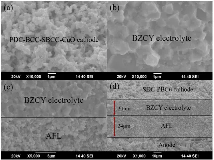
Fig. 5 Cross-section SEM images of (a) PDC-BCC-SBCC-CuO cathode layer, (b) BZCY electrolyte layer, (c) the interface between AFL and BZCY membrane, and (d) the four-layer single cell with an AFL and PDC-BCC-SBCC-CuO cathode after testing.
of SDC-PBCu annealed at 900 °C, as shown in Fig. 4(c).It can be clearly seen that the quaternary PBCC PDC-BCC-SBCC-CuO was formed with the Pr diffusion strategy based on SDC-PBCu compound. The lattice spacings of 0.32, 0.17, 0.32 and 0.31 nm correspond to the (111) crystal plane of Ce1-xPrxO2-δ, the (020) crystal plane of CuO, the (105) crystal plane of Sm2Ba1.33Ce0.67Cu3O9 and the (112) crystal plane of Ba2CeCu3O7.4, respectively. Although the SDC-PBCu composite after calcined at 900 °C can not be incapable of retaining the SDC and PBCu phase structure non-destructively, all the new phase structure materials Ce1-xPrxO2-δ, Ba2CeCu3O7.4, Sm2Ba1.33Ce0.67Cu3O9 and CuO could advance the occurrence of ORR. The mixed cathode material with both high electro-catalytic and ORR ability might transfer the oxygen ions (O2-) timely, boosting the dissociation of the oxygen molecule and taking the ORR in progress, which is favorable for improving the electrochemical performance. By applying this mixed PBCC material PDC-BCC-SBCC-CuO to H-SOFC, it supposed to have preeminent performance output in principle. Therefore, we decided to evaluate the electrochemical performance on the BZCY electrolyte-based single cell to check it further.
3.2.
Microstructures
AFL layer, an appropriate proportion of NiO could be able to guarantee sufficient porosity and adequate numbers and length of NiO-BZCY-gas TPBs, which is closely related with the whole cell performance. In this work, the NiO-BZCY with 65 wt.% NiO is used as AFL for the BZCY-based cell to evaluate the performance of PDC-BCC-SBCC-CuO cathode. As shown in Fig. 5(d), all the anode, AFL and cathode has a porous structure. The starch has been added to the anode as the pore forming materials, while the pore size in AFL is much smaller than that of the anode. The small pores in AFL provide the electrochemical reaction sites for H2 dissociation, while the larger pores in anode ensure the fast diffusion of fuel gas. Both the AFL and cathode are well adhered on both sides of dense BZCY membrane and the four layers (including anode, AFL, BZCY electrolyte and SDC-PBCu cathode) in the single cell have no sign of cracking or delamination, indicating the four-layer structured single cell with an AFL could keep the good microstructures and no thermal mismatch happened during the thermal cycles. The thickness of electrolyte is ~ 20 μm and the thickness for AFL is ~ 24 μm. In this study, based on the excellent H-SOFC structure, it is expected to obtain impressive electrochemical performance in low temperatures when the mixed PBCC PDC-BCC-SBCC-CuO is applied as the cathode for BZCY-based cell.
3.3.
Electrochemical performance of the single cell
Fig. 6 I-V and I-P curves of the single cell NiO-BZCY|AFL|BZCY|PDC-BCC-SBCC-CuO measured at 450-700 °C.
[image:7.595.304.551.70.232.2]To evaluate the performance of the mixed PBCC PDC-BCC-SBCC-CuO for H-SOFC in LT operation range, the button cell with an NiO-BZCY anode, an AFL, the BZCY electrolyte and PDC-BCC-SBCC-CuO cathode was fabricated and measured
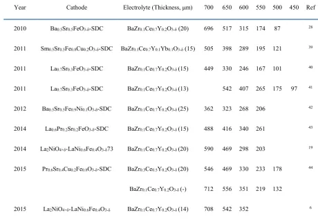
Table 1 Comparison of the MPD (mW cm-2) performance of cobalt-free composite PBCs using BaCeO3-based cell reported in the literature and in the present study.
Year Cathode Electrolyte (Thickness, μm) 700 650 600 550 500 450 Ref
2010 Ba0.5Sr0.5FeO3-δ-SDC BaZr0.1Ce0.7Y0.2O3-δ (20) 696 517 315 174 87 28
2011 Sm0.5Sr0.5Fe0.8Cu0.2O3-δ-SDC BaZr0.1Ce0.7Y0.1Yb0.1O3-δ (15) 505 398 289 195 121 39
2011 La0.7Sr0.3FeO3-δ-SDC BaZr0.1Ce0.7Y0.2O3-δ (15) 449 330 246 167 101 40
2011 La0.7Sr0.3FeO3-δ-SDC BaZr0.1Ce0.7Y0.2O3-δ (13) 542 407 265 175 97 41
2012 Ba0.5Sr0.5Fe0.9Ni0.1O3-δ-SDC BaZr0.1Ce0.7Y0.2O3-δ (25) 362 323 268 206 42
2014 La0.6Pr0.2Sr0.2FeO3-δ-SDC BaZr0.1Ce0.7Y0.2O3-δ (15) 488 416 340 261 43
2014 La2NiO4+δ-LaNi0.6Fe0.4O3-δ73 BaZr0.1Ce0.7Y0.2O3-δ (20) 590 469 298 203 19
2015 Pr0.6Sr0.4Cu0.2Fe0.8O3-δ-SDC BaZr0.3Ce0.5Y0.2O3-δ (20) 546 469 330 233 178 44
BaZr0.1Ce0.7Y0.2O3-δ (-) 712 556 351 219 132
[image:7.595.64.525.418.739.2]This work PDC-BCC-SBCC-CuO BaZr0.1Ce0.7Y0.2O3-δ (20) 1000 794 566 336 175 83
Fig. 7 (a) EIS of the single cell NiO-BZCY|AFL|BZCY|PDC-BCC-SBCC-CuO measured under open-circuit conditions from 450 to 700 °C, (b) the temperature dependence of the ohmic resistance (RO), polarization resistance (RP) and total resistance (RT), as well as the ratio RP/ RT of the single cell with BCC-SBCC-CuO cathode, and (c) the Arrhenius plots for Rp of PDC-BCC-SBCC-CuO estimated from the EIS in this study and the cobalt-free composite PBCs reported in the literature.
under conventional conditions using static air as the oxidant and humidified hydrogen as the fuel gas. Fig. 6 shows typical I-V and
I-P curves of the cell NiO-BZCY|AFL|BZCY|PDC-BCC-SBCC-CuO measured at 450-700 °C. The open-circuit voltages (OCVs) of the cell with PDC-BCC-SBCC-CuO cathode after anode reduction are 1.004, 1.033, 1.052, 1.069, 1.083 and 1.1V, accompanied with the corresponding maximum power densities (MPDs) of 1000, 794, 566, 336, 175 and 83 mW cm-2 at 700, 650, 600, 550, 500 and 450 °C, respectively. The high OCV values confirm that the electrolyte membrane is sufficiently dense to resist gas leakage. As shown in Table 1, the single cell with PDC-BCC-SBCC-CuO cathode shows higher MPDs than most PBCCs reported in the literature at all testing temperatures. Although LSF-SDC 41 displays a little higher MPD output than BCC-SBCC-CuO at 450 °C, the cell performance of PDC-BCC-SBCC-CuO cathode based on BaCeO3-based electrolyte shows almost the largest MPDs ever reported at above 500 °C, suggesting the outstanding electrochemical properties of the mixed PBCC PDC-BCC-SBCC-CuO in the LT operation range, which may be attributed to high electro-catalytic activity of BCC and SBCC.
However, in the developed cobalt-free PBCCs, although quite a few PBCCs present preferable cell performance, such as Ba0.5Sr0.5FeO3-δ-SDC 28, Sm0.5Sr0.5Fe0.8Cu0.2O3-δ-SDC 39, La0.6Pr0.2Sr0.2FeO3-δ-SDC 43 and La2NiO4+δ-LaNi0.6Fe0.4O3-δ6, 19, most PBCCs possess better performance only at intermediates (600-800 °C, e.g. 700 °C) while the performance at LT down to 500 °C is inferior. Simultaneously, the PDC-BCC-SBCC-CuO has similar performance output with La0.7Sr0.3FeO3-δ-SDC 41 and Pr0.6Sr0.4Cu0.2Fe0.8O3-δ-SDC 44 at 500 °C and much higher MPD performance than the reported cobalt-free composite PBCs at the temperature range 550-700 °C, which indicates that PDC-BCC-SBCC-CuO is a preferable HPLT cobalt-free PBC material for H-SOFC.
[image:8.595.43.293.87.610.2]increases from 0.212 to 0.737 Ω cm2 under the same working conditions. The RP values are 0.037, 0.084, 0.188, 0.538, 2.087 and 7.835 Ω cm2, with the corresponding RO values of 0.212, 0.248, 0.293, 0.361, 0.512 and 0.737 Ω cm2 at 700, 650, 600, 550, 500 and 450 °C, respectively. Evidently, the ratios of RP/RT are 15.02%, 25.27%, 39.11%, 59.88%, 80.30% and 91.41% with the decreasing temperature ranging from 700 to 450 °C, and the RP controls the downhill trend of RT below 550°C, playing a leading role in determining the total resistance of the single cell. Then more attention could be paid to the exploration of electrode materials with high activity at low temperatures to decrease the RP, thus enhancing the performance of BZCY-based cell, and benefiting the SOFC LT operation.
As shown in Fig. 7(c), the Ea of multifarious cobalt-free composite PBCs calculated by the Arrhenius equation is listed. Though the Ea of the RP is higher than that of most reported cobalt-free PBCCs in the literature, corresponding to the value of 1.31 eV for PDC-BCC-SBCC-CuO, Ba0.5Sr0.5FeO3-δ-SDC 28 has a much higher Ea (1.44 eV). The La0.6Pr0.2Sr0.2FeO3-δ-SDC 43 cathode possesses almost equivalent polarization performance with PDC-BCC-SBCC-CuO cathode in this work at lower operation temperatures, which has the RP value of 0.51 Ω cm2at 550 °C. Worthy of attention is that the RP of PDC-BCC-SBCC-CuO is lowest in the developed cobalt-free composite PBCs except for the RP of La0.6Pr0.2Sr0.2FeO3-δ-SDC 43 at 550 °C, indicating the preeminent ORR catalytic activity and excellent oxygen transfer ability, which could make it clear that the PDC-BCC-SBCC-CuO is an outstanding PBC material for H-SOFC. The relatively high Ea of PDC-BCC-SBCC-CuO in the whole operating temperature range could also illustrate it that the cathode has a strong dependency relationship with the testing temperature. Then the RP of PDC-BCC-SBCC-CuO increases more rapidly, being consist with the little higher cell MPD performance degradation rate which could be seen from Table 1. This phenomenon may be ascribed to the relatively fast decay of electro-catalytic ability for the manifold phases in PDC-BCC-SBCC-CuO cathode, affecting the numbers of the effective TPBs and the ORR kinetics at LTs down to 450 °C. That is to say, the invalid TPBs hinder the ORR kinetics and the oxygen transfer rate.
In addition, the long-term stability performance of the single cell with PDC-BCC-SBCC-CuO cathode was conducted.The OCV kept stable for 60 h which indicates that the structure of the single cell was not broken after operating 60 h under open circuit condition (Supplementary Fig. S3(a)). Interestingly, the power density is around 450 mW cm-2 at the beginning of the stability test under 0.7 V at 600 °C, and then increase to about 500 mW cm-2 after 25 h. The power output kept stable at 500 mW cm-2for another 20 h and then decrease to 450 mW cm-2. Anyhow, during the 60 h stability test, the single cell power output almost has no degradation (Supplementary Fig. S3(b)). The good long-term performance could illustrate that the PDC-BCC-SBCC-CuO cathode has fine chemical stability against water vapor and CO2 in ambient air, and the PDC-BCC-SBCC-CuO cathode obtained with Pr diffusion strategy is a promising cathode for HPLT H-SOFCs.
In view of the reaction between SDC and PBCu has some infaust effect to the cell performance at lower temperatures, especially at the temperature down to 450 °C, the ionic conductive phase SDC could be replaced by other structured materials which should have no adverse reaction with PBCu, avoiding both new phase resultant to help using the high oxygen ion conductivity and oxygen catalytic ability to design the low-cost cobalt-free PBC material. The method of doping of A-site or B-site cations in the PBCu layered perovskite structure can also be adopted to obtain a good thermal-matching material, which could be conducive to exert wonderful intrinsic properties of PBCu.
4.
Conclusions
The present work develops an in-situ Pr diffusion strategy to achieve a quaternary compound PDC-BCC-SBCC-CuO acting as a PBC candidate for LT H-SOFC. After the treatment of the composite powder SDC-PBCu at 900 °C, several reaction peaks in XRD appeared, which might be attributed to the easily diffusion of Pr element into SDC phase to form fluorite structured solid solution Ce1-xPrxO2-δ with higher oxygen ion conductivity and oxygen vacancy concentration, thus improving the cathode ORR kinetics and the transportation capacity of oxygen. The phenomenon of Pr diffusion may result in the migration of Sm and Ce, occupying the Pr-sites in PBCu layered structure with the formation of several new phase materials containing fluorite structured Ce1-xPrxO2-δ, orthorhombic layered material Ba2CeCu3O7.4, tetragonal perovskite-related Sm2Ba1.33Ce0.67Cu3O9 and the metallic oxide CuO. To some extent, the new phase materials could boost the whole ORR at the cathode for the fine oxygen transfer speed and electro-catalytic ability. With the BZCY electrolyte and an NiO-BZCY AFL, the PDC-BCC-SBCC-CuO PBC candidate achieved an encouraging performance with the MPD of 1000, 794, 566, 336, 175 and 83 mW cm-2, and the RP of 0.037, 0.084, 0.188, 0.538, 2.087 and 7.835 Ω cm2 at 700, 650, 600, 550, 500 and 450 °C, respectively. The almost highest power output above 500 °C compared with the reported cobalt-free PBCCs on BaCeO3 -based H-SOFC in the literature and the nearly lowest polarization properties reveal the commendable potential for working in LTs. Although the Ea of PDC-BCC-SBCC-CuO cathode is slightly higher, the encouraging cell performance at LTs could illustrate it that the novel high catalytic activity cobalt-free PBC PDC-BCC-SBCC-CuO is a superior alternative for HPLT H-SOFC.
Acknowledgements
Notes and references
1. C. C. Duan, J. H. Tong, M. Shang, S. Nikodemski, M. Sanders, S. Ricote, A. Almansoori and R. O'Hayre, Science, 2015, 349, 1321-1326.
2. J. Hou, L. Bi, J. Qian, Z. Zhu, J. Zhang and W. Liu, Journal of Materials Chemistry A, 2015, 3, 10219-10224.
3. E. D. Wachsman and K. T. Lee, Science, 2011, 334, 935-939. 4. L. Bi, S. Boulfrad and E. Traversa, Chemical Society Reviews,
2014, 43, 8255-8270.
5. L. Bi, E. H. Da'as and S. P. Shafi, Electrochemistry Communications, 2017, 80, 20-23.
6. J. Hou, J. Qian, L. Bi, Z. Gong, R. Peng and W. Liu, J. Mater. Chem. A, 2015, 3, 2207-2215.
7. G. Ma, T. Shimura and H. Iwahara, Solid State Ionics, 1998, 110, 103-110.
8. S. V. Bhide and A. V. Virkar, Journal of The Electrochemical Society, 1999, 146, 2038-2044.
9. D. Pergolesi, E. Fabbri, A. D'Epifanio, E. Di Bartolomeo, A. Tebano, S. Sanna, S. Licoccia, G. Balestrino and E. Traversa, Nature Materials, 2010, 9, 846-852.
10. N. Zakowsky, S. Williamson and J. Irvine, Solid State Ionics, 2005, 176, 3019-3026.
11. L. Bi, S. Zhang, S. Fang, Z. Tao, R. Peng and W. Liu, Electrochemistry Communications, 2008, 10, 1598-1601. 12. W. Sun, S. Fang, L. Yan and W. Liu, Journal of The
Electrochemical Society, 2011, 158, B1432.
13. C. Zuo, S. Zha, M. Liu, M. Hatano and M. Uchiyama, Advanced Materials, 2006, 18, 3318-3320.
14. L. Bi, S. Zhang, S. Fang, L. Zhang, K. Xie, C. Xia and W. Liu, Electrochemistry Communications, 2008, 10, 1005-1007. 15. Z. Gao, L. V. Mogni, E. C. Miller, J. G. Railsback and S. A.
Barnett, Energy Environ. Sci., 2016, 9, 1602-1644.
16. N. Mahato, A. Banerjee, A. Gupta, S. Omar and K. Balani, Progress in Materials Science, 2015, 72, 141-337.
17. C. Sun, R. Hui and J. Roller, Journal of Solid State Electrochemistry, 2010, 14, 1125-1144.
18. K. Xie, R. Yan and X. Liu, Electrochemistry Communications, 2009, 11, 1618-1622.
19. J. Hou, Z. Zhu, J. Qian and W. Liu, Journal of Power Sources, 2014, 264, 67-75.
20. Z. Tao, L. Bi, L. Yan, W. Sun, Z. Zhu, R. Peng and W. Liu, Electrochemistry Communications, 2009, 11, 688-690.
21. Z. Tao, L. Bi, Z. Zhu and W. Liu, Journal of Power Sources, 2009, 194, 801-804.
22. Z. Zhu, J. Qian, Z. Wang, J. Dang and W. Liu, Journal of Alloys and Compounds, 2013, 581, 832-835.
23. A. Evans, J. Martynczuk, D. Stender, C. W. Schneider, T. Lippert and M. Prestat, Advanced Energy Materials, 2015, 5, 1400747. 24. Z. Zhu, Z. Tao, L. Bi and W. Liu, Materials Research Bulletin,
2010, 45, 1771-1774.
25. Y. Ling, L. Zhao, X. Liu and B. Lin, Fuel Cells, 2015, 15, 384-389.
26. A. Grimaud, F. Mauvy, J. Marc Bassat, S. Fourcade, M. Marrony and J. Claude Grenier, Journal of Materials Chemistry, 2012, 22, 16017.
27. W. Sun, L. Yan, B. Lin, S. Zhang and W. Liu, Journal of Power Sources, 2010, 195, 3155-3158.
28. W. Sun, Z. Shi, S. Fang, L. Yan, Z. Zhu and W. Liu, International Journal of Hydrogen Energy, 2010, 35, 7925-7929.
29. F. He, T. Wu, R. Peng and C. Xia, Journal of Power Sources, 2009, 194, 263-268.
30. C. Yang and Q. Xu, Journal of Power Sources, 2012, 212, 186-191.
31. H. Ding and X. Xue, International Journal of Hydrogen Energy, 2010, 35, 4311-4315.
32. B. H. Rainwater, M. Liu and M. Liu, International Journal of Hydrogen Energy, 2012, 37, 18342-18348.
33. R. Chiba, H. Taguchi, T. Komatsu, H. Orui, K. Nozawa and H. Arai, Solid State Ionics, 2011, 197, 42-48.
34. A. A. Taskin, A. N. Lavrov and Y. Ando, Progress in Solid State Chemistry, 2007, 35, 481-490.
35. S. Sengodan, S. Choi, A. Jun, T. H. Shin, Y.-W. Ju, H. Y. Jeong, J. Shin, J. T. S. Irvine and G. Kim, Nat Mater, 2015, 14, 205-209. 36. L. Bi, Z. Tao, W. Sun, S. Zhang, R. Peng and W. Liu, Journal of
Power Sources, 2009, 191, 428-432.
37. W. Sun, L. Yan, Z. Shi, Z. Zhu and W. Liu, Journal of Power Sources, 2010, 195, 4727-4730.
38. C. J. Howard, G. R. Lumpkin, R. I. Smith and Z. Zhang, Journal of Solid State Chemistry, 2004, 177, 2726-2732.
39. Y. Ling, J. Yu, B. lin, X. Zhang, L. Zhao and X. Liu, Journal of Power Sources, 2011, 196, 2631-2634.
40. Q. Li, L.-P. Sun, L.-H. Huo, H. Zhao and J.-C. Grenier, Journal of Power Sources, 2011, 196, 1712-1716.
41. W. Sun, Z. Zhu, Y. Jiang, Z. Shi, L. Yan and W. Liu, International Journal of Hydrogen Energy, 2011, 36, 9956-9966.
42. Y. Ding, Y. chen, X. Lu and B. Lin, International Journal of Hydrogen Energy, 2012, 37, 9830-9835.
43. Y. Chen, Q. Gu, D. Tian, Y. Ding, X. Lu, W. Yu, T. T. Isimjan and B. Lin, International Journal of Hydrogen Energy, 2014, 39, 13665-13670.