DEVELOPMENT OF ALL-SOLID-STATE
MODELOCKED LASER SOURCES AT 1.55 ΜM
Gareth J. Valentine
A Thesis Submitted for the Degree of PhD
at the
University of St Andrews
1999
Full metadata for this item is available in
St Andrews Research Repository
at:
http://research-repository.st-andrews.ac.uk/
Please use this identifier to cite or link to this item:
http://hdl.handle.net/10023/14790
Development of All-so lid-state
Modelocked Laser Sources at 1.55 pm
Thesis submitted for the degree of Doctor of Philosophy
to the University of St. Andrews
Gareth J. Valentine B.Sc.
J.F. Allen Physics Research Laboratories School of Physics and Astronomy University of St. Andrews North Haugh
St. Andrews Fife KY16 9SS
ProQuest Number: 10166670
All rights reserved
INFORMATION TO ALL USERS
The quality of this reproduction is d e p e n d e n t upon the quality of the copy subm itted.
In the unlikely e v en t that the author did not send a co m p le te m anuscript and there are missing p ag es, these will be noted. Also, if m aterial had to be rem oved,
a n o te will indicate the deletion.
uest
ProQuest 10166670
Published by ProQuest LLO (2017). Copyright of the Dissertation is held by the Author.
All rights reserved.
This work is protected against unauthorized copying under Title 17, United States C o d e Microform Edition © ProQuest LLO.
ProQuest LLO.
789 East Eisenhower Parkway P.Q. Box 1346
Declarations
I, Gareth John Valentine, hereby certify that this thesis, which is approximately sixty thousand words in length, has been written by me, that it is the record of work carried out by me and that it has not been submitted in any previous application for a higher degree.
I was admitted as a research student and as a candidate for the degree of Doctor of Philosophy in October 1993; the higher study for which this is a record was carried out at the University of St. Andrews between 1993 and 1998.
In submitting this thesis to the University of St. Andrews I understand that I am giving permission for it to be made available for use in accordance with the regulations of the University Library for the time being in force, subject to any copyright vested in the work not being affected thereby. I also understand that the title and abstract will be published, and that a copy of the work may be made and supplied to any bona fide library or research worker.
Date 1 / 2/
I
Signature of candidate(
OcUe^
V fI hereby certify that the candidate has fulfilled the conditions of the Resolution and Regulations appropriate for the degree of Doctor of Philosophy in the University of St. Andrews and that the candidate is qualified to submit this thesis in application for that degree.
Abstract
This thesis concerns the generation of tunable ultrashort pulses near the 1.55 pm telecommunications window. Two principal laser systems are considered: i) the NaClrOH" colour-centre laser, which employs the technique of synchronously-pumped modelocking to generate tunable picosecond pulses and ii) the self-modelocked Cr^^iYAG laser to generate femtosecond pulses tunable from 1.5-1.56 pm.
Details are given for an all-solid-state cw and cw-modelocked pump source for Cr"^^:YAG and colour-centre lasers based on NdiYAG. Fibre-coupled AlGaAs laser diodes are employed as the solid-state pump source to this laser. When operated cw, up to 8.5 W of linearly polarised output power in a TEMoo beam is obtained. A compact cw actively-modelocked Nd:YAG laser is described having a pulse repetition rate of 194 MHz. Pulse durations down to 34 ps and output powers up to 6.0 W are obtained from this system. An 82 MHz Nd:YV0 4 laser is also detailed producing pulsewidths
down to 75 ps and average output powers up to 3.5 W.
The intrinsic noise source associated with the synchronous modelocking technique is discussed and a simple passive stabilisation scheme, coherent-photon-seeding (CPS), is described and applied to the synchronously-modelocked NaChOH* laser. Results of a simulation of this laser are reported and a comparison is made with the practical observations of the stabilised laser. For the first time, theoretical and experimental evidence for the presence of high frequency pulse jitter in synchronously-pumped- modelocked (SPML) lasers is presented and the coherent photon seeding technique is shown to eliminate this noise.
Contents
Introduction
1.1 Overview_________________________________________________________ 1 1.2 Modelocking Techniques___________________________________________ 2 1.3 Ultrashort Pulse Characterisation____________________________________ 12 1.4 Ultrashort Pulse Propagation________________________________________ 22 1.5 Summary________________________________________________________ 30
2 Construction of an All-solid-state Nd:YAG Pump Laser _________ 36
2.1 Introduction______________________________________________________ 36 2.2 The Mainframe SP3800 Nd’*:YAG Laser_____________________________38 2.3 AlGaAs Laser Diodes for Pumping Nd:YAG__________________________ 43 2.4 Design of a High Power cw Nd:YAG Laser___________________________ 47 2.5 Actively Modelocked All-solid-state Nd^^iYAG Laser ______________63 2.6 Construction of an Actively Modelocked Nd^^: YVO4 Laser Operating at
82 M Hz__________________________________________________________ 84 2.7 Concluding Remarks_______________________________________________88
3 Passive Stabilisation of a Synchronously-modelocked
NaCliOH" Colour-centre Laser______________________
95
3.1 Introduction_______________________________________________________ 95 3.2 Actively Modelocked NaCl :OH' Laser Using Synchronous Pumping _____98 3.3 Numerical Modelling of Synchronously-modelocked Lasers_____________ 101 3.4 Passive Stabilisation Using Coherent-photon-seeding__________________ 111 3.5 Coherent-photon-seeding Applied To The Synchronously-modelocked
4 The CW C/+:YAG L aser_____________________________________ 143
4.1 Introduction_____________________________________________________ 143 4.2 Vibronic Gain Media______________________________________________ 143 4.3 TheCr^^IoninYAG______________________________________________ 148 4.4 Spectroscopy and Growth of Cr"^^: Y A G ______________________________ 149 4.5 Construction and Operation of a CW Cr"^^:YAG L aser__________________157 4.6 Requirements for a Self-Modelocked Cr"^^: YAG Laser__________________177 4.7 Concluding Remarks______________________________________________ 180
5 Construction of an Efficient, Femtosecond Cr'*^;YAG Laser________ 186
5.1 Introduction_____________________________________________________ 186 5.2 Construction of a Self-modelocked Cr"^^: YAG Laser Based on a 4-mirror
Z-cavity Geom etiy_______________________________________________ 188 5.3 Development of an Efficient 3-mirror C/^:YAG Laser__________________191 5.4 Noise Characterisation of the All-solid-state, Compact 3-mirror Cr^^iYAG
L aser___________________________________________________________223 5.5 Highly Asymmetric 4-mirror Resonator Designs_______________________226 5.6 Novel 4-mirror Cavity Design for Low cw-threshold or High Pump Powers 236 5.7 Concluding Remarks______________________________________________ 239
6 Major Conclusions
____
245
7
Appendix I;
Stepping Model o f the Linear Cavity
Synchronously-modelocked Laser with Coherent Photon Seeding
_____________________251
8
Appendix II:
ABCD Model for Self-Modelocked Three-mirror Lasers
266
9
Appendix III:
Kostenbauder model to examine dispersive cavities
_____275
Publications:_________________________
292
Introduction
1.1 Overview
1998 is the 40* anniversary of Schawlow and Townes' proposition for a source of ‘extremely monochromatic and coherent light'\ Since the first practical demonstration of the ‘optical maser’^, lasers have found countless applications ranging from those which exploit the coherent nature of laser light (e.g. producing holograms), to those that utilise their ability to create highly intense focused spots (e.g. industrial machining and laser surgery). However, it is the lesser-well-known ability of certain lasers to generate exceptionally high peak power light pulses of amazingly brief durations which this work describes. These ‘ultrafast' lasers have been justly described as ‘the Cadillacs of research tools'^. It has been desirable to measure events of ever shorter duration tlii'oughout history and currently, the fastest man-made events are pulses obtained from mode-locked lasers (-6.5 fs"^ recently reported) which may be used to study ultrafast phenomena especially those occurring in chemistry, biology, physics and optoelectronics.
One particular area of interest of ultrafast lasers is in the characterisation of semiconductor materials with emphasis on research into devices operating at 1550 nm. This region is attractive as it corresponds to the low-loss wavelength window for silica- based optical-fibres (-0.2 dB/km) and hence is important for optical telecommunications. For complete characterisation of these optoelectronic devices (such as laser diodes, diode amplifiers, modulators, switches and detectors), it is necessary to have access to ultrafast sources with broad wavelength tunability, reasonably high output powers and pulse durations down to -100 fs.
realisation of a compact, low-cost all-solid-state replacement for coloui-centre lasers and much of the work presented here was aimed towards developing such a system.
Fundamental to reducing the cost of ultrafast laser systems is reducing the pump power requirement. This involves maximising the efficiency of the modelocked laser whilst reducing the threshold for cw and modelocked operation permitting the deployment of smaller and cheaper pump lasers.
In chapter 2, details of the construction of an all-solid-state Nd^^:YAG pump laser are given, capable of pumping both Cr"^^:YAG lasers (when operated cw) and modelocked colour-centre lasers (when actively modelocked). This is more compact and cheaper to run than the mainframe arc-lamp pumped system which it was designed to replace.
Chapter 3 describes a simple, but highly effective technique for stabilising a synchronously-modelocked NaCkOH' colour-centre laser. This dramatically improves the stability of the modelocked pulse sequence and permits ‘tuning’ of the pulse duration by simply adjusting the laser cavity length.
The Cr"^^:YAG laser is introduced in chapter 4, and in chapter 5 the considerations to be made in designing a femtosecond laser system with minimal pump power requirements are described.
1.2 M odelocking Techniques
frequency dependence of the amplitude and phase of light forni a Fourier transform pair.
Several techniques have been developed to achieve modelocking, but all these methods fall under one of two categories, namely active or passive modelocking. For a comprehensive early review on modelocking techniques see reference 8.
1.2.1 Active modelocking
Active modelocking involves modulating either the overall laser loss or gain with an external frequency source. Applying amplitude modulation at a frequency equal to the longitudinal mode spacing forces each mode to acquire sidebands and hence by transferring power from each mode to its nearest neighbours, the phases of the oscillating modes are locked together. The pulse repetition frequency of actively modelocked lasers is governed by an external signal independent of the laser cavity.
Amplitude modulation
This conceptually simple technique essentially involves placing an optical shutter at one end of the laser cavity which is opened at the same rate as the cavity period. The light approaching the modulator when the modulator loss is minimum will see most gain, outside this region the light will experience net loss leading to the formation (after many round trips) of an optical pulse.
In practice the loss modulator is an acousto-optic device driven with a sinusoidal signal obtained from an external signal generator. An acoustic standing wave is induced in the modulator block whose magnitude depends on the amplitude of the applied RF- signal. A phase grating is generated by the local refractive index change induced by the acoustic standing wave. Intracavity power is diffracted outside the cavity at all points where the applied signal is non-zero, hence the cavity losses are minimum twice during each cycle of the RF-signal and so the pulse repetition frequency is twice the frequency of the electrical drive signal. The laser cavity period must be set to be equal to the period of the modelocked pulse sequence for the generation of the shortest pulses^.
Frequency modulation
An alternative active modelocking technique involves placing an electro-optic modulator at one of the cavity driven by a synthesised RF-signal. The refractive index of the electro-optic material is modulated by the applied RF-signal via the Pockels effect. This frequency shifts the circulating laser light except at the points where the applied rate of change of field is zero. Loss modulation effectively results when the circulating light is frequency shifted outside the gain bandwidth of the laser. Hence a pulse train develops at the two turning points of the RF-signal where the induced rate of change of phase shift is zero. The RF-signal is therefore applied at half the laser cavity repetition frequency. Note that two pulse trains are effectively formed at the two extremes of the RF electrical drive cycle (i.e. 180 degrees out of phase). These two sequences are independent and can exhibit individual characteristics and can lead to an instability in the modelocked pulse train. One advantage FM modulators have over AM modulators is the resonant frequency is not limited by the physical design of the device to the same extent as acousto-optic modulators, hence much higher repetition rates (and therefore more compact laser cavities) can be realised by employing FM modelocking. From the Kuizenga-Siegman^ theory, the pulse duration from an actively modelocked laser is inversely proportional to the square root of the pulse repetition frequency, hence a compact FM-modelocked laser should produce pulses of shorter duration than an AM- modelocked laser. An additional advantage of FM-modulators is the absence of a temperature dependence of the resonant frequency, thus no active stabilisation is necessary to maintain efficient modulation as may be required with AM-modulation (see chapter 3).
Gain modulation
This modelocking technique is applicable both to electrically pumped semiconductor lasers and lasers pumped by a second laser which is modelocked. In the latter case it is termed ‘synchronously-pumped modelocking (SPML)’, (described in detail in chapter 3 applied to the NaChOH' laser).
an extended cavity by anti-reflection coating one of the diode facets (the other being HR coated) and using an external mirror to complete the resonator‘°’‘^’’^’‘h An alternative scheme is to place a laser diode, with both facets AR coated, in the centre of a resonator and applying RF power at a frequency twice that of the cavity repetition rate.
Synchronous-modelocking is most suited for systems based on gain media having upper-state lifetimes of the order of the laser cavity round trip times and large gain cross-sections such as dye and colour-centie lasers. The optical lengths of the pumped (slave) laser and the master laser must be matched to within ~5 pm for optimum modelocking. Dynamic gain saturation shortens the trailing edge of the SPML pulse, which results in an asymmetric pulse with a duration significantly shorter (by - I order of magnitude) than the pulse duration of the pumping laser.
1,2.2 Passive modelocking
In contrast to active modelocking, where the pulse period is governed by a frequency source external to the laser cavity, passive modelocking techniques rely on the circulating laser field to induce a modelocking mechanism.
A nonlinear element is included in the laser resonator which possesses an intensity-dependent loss: high power components (e.g. noise) of the circulating laser field experience the least loss. The maximum emission principle^^'^^ (MEP) states that for given mode amplitudes, the phases o f the individual modes adjust themselves to maximise the rate of stimulated emission inside the gain medium. In the case of passive modelocking, the MEP favours modelocked operation over free running cw operation, as high intensities experience least loss.
Since the pulse shortening in passive modelocking techniques is driven by the circulating laser field itself, significantly shorter pulse durations can be obtained compared to active modelocking schemes. Currently the shortest pulse duration to be obtained dfrectly from a laser (~6 fs '’j was generated by a passive modelocking technique.
Regenerative modelocking
more in common with active modelocking as active modelocking electronics are used with no nonlinear element.
A photodiode having a bandwidth -300 MHz, detects the weak longitudinal mode beating of the cw un-modelocked laser. After filtering and dividing the frequency of the electrical signal to half the mode spacing frequency, the signal is amplified and used to drive a modulator (either acousto-optic or electr o-optic) placed at one end of the laser cavity. Provided that the phase of the RF-signal thus derived is set conectly, a modelocked pulse will develop inside the cavity. Any environmentally induced fluctuations in the laser cavity length will be linked to a change in the fr equency of the modulator drive signal thus ensuring immunity to cavity length/drive frequency mismatches.
This technique is often used to generate a high intensity modelocked pulse to initiate a second passive modelocking mechanism, especially self-modelocking, as it is essentially self-starting.
Passive modelocking using fast saturable absorbers
This is conceptually the most straightfoiward form of passive modelocking. An absorbing element which saturates on instantaneous intensity, is placed inside the cavity. After switching on the laser, the most intense noise feature will be preferentially amplified as this will saturate the absorber greatest and hence will experience the least loss. Because it is only the instantaneous intensity of the laser field which modulates the absorber, this is termed self-amplitude modulation (SAM). After many round trips, this noise feature develops into a modelocked pulse sequence. Because the only pulse shaping mechanism is saturation of the loss, the final pulse duration is limited to the recovery time of the absorber usually -10 ps.
Passive modelocking using slow saturable absorbers
lasers). A narrow gain window results if the saturation energy and recovery time of the absorber are less than those of the gain medium.
By carefully positioning the absorbing medium in a bi-dhectional ring cavity, a grating is established by two counter-propagating pulses inside the absorber leading to enhanced loss saturation. This technique called colliding-pulse modelocking^® (CPM) has enabled sub 20 fs pulses to be obtained directly from a dye laser^' (with suitable dispersion compensation).
Hybrid modelocking
In certain cases when modelocking with a slow saturable absorber is desirable, it may be more practicable to pump the laser using a modelocked pump source. This may be due to the fact that the recovery time of the gain is less than that of the absorber medium making passive modelocking impossible. In these instances, hybrid modelocking may be adopted where gain modulation by synclironous-pumping is assisted by a weak saturable absorber^^. But this is really an active modelocking technique as the pulse repetition frequency is controlled by the master (pump) laser frequency.
Passive modelocking using synthetic fast saturable absorbers
It is possible to obtain modelocking using artificial saturable absorbers based on fast reactive (as opposed to resistive) nonlinearities. The laser must be configured so that the effects of the nonlinearity induce amplitude modulation of the circulating laser field. The nonlinearity is then behaving as a saturable absorber with an almost instantaneous recovery time permitting the generation of pulses of exceptionally short duration.
Coupled cavity modelocking
Self-phase modulation (SPM) may be successfiilly employed to obtain passive modelocking by constructing the laser as an interferometer with the nonlinear element placed in one arm. Fabry-Perot, Michelson and Sagnac interferometers have been used for modelocking. An intense noise feature will experience an intensity-dependent phase shift on propagating tlirough the nonlinear element (often monomode optical fibre). If the two interferometer arms are suitably aligned, it is possible after recombining the nonlinear arm with the main cavity, for constructive interference to occur at the centre of the noise feature thus enhancing the peak intensity, whilst destructive interference suppresses the wings of the noise feature. After many round trips, a modelocked pulse sequence results^®.
This modelocking technique termed ‘coupled-cavity modelocking’ (CCM) (also called ‘additive-pulse modelocking’ (APM)) was first demonstrated with a synchronously-modelocked KC1:T1^®^ colour-centre laser^'* where the synclironous- pumping merely served to initiate this passive modelocking mechanism. It was subsequently applied to other solid-sate laser systems including Nd^^iYAG^®, Nd^^rYLF^®, Nd^^:glass^’, Tiisapphhe^®, NaChOH'^^ and Cr"^^:Forsterite®° although in most cases it has been superseded by the simpler self-modelocking technique. One major drawback of this technique is the necessity to maintain interferometrical matching of the linear and nonlinear arm lengths. Tills often requires the addition of some form of electronic active stabilisation scheme®' which adds to the overall complexity of the laser.
Self-modelocking
In 1990 it was observed by Spence et al.®^ that passive modelocking could be established in a Ti:sapphire laser cavity with no apparent modelocking element. Initially the pulses were strongly chirped and -2 ps in duration suggesting the presence of uncompensated self-phase modulation. The inclusion of an intracavity prism pair to provide anomalous group-velocity dispersion (GVD) permitted the generation of pulses as short as 60 fs from a self-modelocked (SML) laser.
pair, this is insufficient in itself to establish modelocking. Some foim of discrimination is required to favour modelocked operation above normal cw-operation (to satisfy the maximum emission principle). At first it was thought that self-amplitude modulation resulted from interference between two h ansverse modes of the laser resonator, similar to the coupled-cavity modelocking scheme, as it seemed essential for the laser to operate multimode before modelocking could be achieved. Later, theoretical work®®’®"’®® established that self-amplitude modulation (SAM) was provided by self-focusing via the optical Kerr-effect in the gain medium itself, which induced beam shaping in the laser cavity. By configuring the laser cavity in a suitable fashion, the laser field may experience greater gain for stronger self-focusing thus enhancing the high intensity noise components of the circulating field at the expense of the low intensity cw background. After many round trips a modelocked pulse develops whose final duration depends on the intracavity dispersion.
Herrmann®® suggested three mechanisms by which self-amplitude modulation may be present in a self-modelocked laser. Conceptually, the simplest method is termed ‘hard-aperture self-modelocking’, and involves placing a physical constriction to the intracavity laser field somewhere in the resonator. Often this is a slit placed in front of one of the end-mitrors of the laser cavity slightly clipping the beam in one plane (usually the tangential). The laser cavity is then aligned in such a way that the spot size at the constriction reduces for stronger nonlinear lensing in the gam medium, hence high intensities experience less round trip loss compared to a low intensity cw signal and are enhanced.
A third mechanism involved in self-modelocked lasers is termed ‘gain-guiding’®’. This is a transverse redistribution of the intracavity field inside the gain element induced by the inverted gain medium, resulting in a change in the beam shape throughout the resonator. This phenomenon affects botli hard and soft aperture modelocked lasers and has been shown by modelling to change the stability limits of the laser resonator.
A simple design procedure for self-modelocked laser cavities has been developed by Cerullo et al.®®’®®’"®’"*’"^ which will be described in detail in chapter 5. Even though this model neglects gain-guiding and gain-saturation and only considers a 2-dimensional plane inside the laser resonator, it allows a laser designer to assess the suitability of a novel cavity design for self-modelocking. This was employed during the design of the unconventional three-mirror and four-mirror laser designs in chapter 5.
In most instances, self-modelocking is not self-starting. This is especially true when the laser is operating close to the cw threshold and to initiate SML a mechanism is usually required to introduce a noise feature inside the laser cavity. This could be a weak saturable absorber element"®, an extracavity moving mirror"" a semiconductor saturable absorber mirror structure" (SESAM) or simply physically tapping or translating a cavity end-mirror®^. An alternative, convenient technique is to deploy regenerative modelocking*^ as described above in section 1.2.2.1. Synchronous- pumping has also been deployed to initiate self-modelocking in several systems"® but the active nature of this scheme can cause problems once passive modelocking is established: the repetition rate of the pump laser and the passively-modelocked laser may be different leading to a modulation of the laser output. Recently, it has been shown that with carefiil cavity design and alignment, that it is possible to achieve self start self-modelocking"* which uses the weak noise features present within a free- running cw laser to initiate the self-modelocking mechanism.
the modelocking mechanism. Also a second nonlinear element was included in both these systems in a tightly focusing pait of the cavity to act as the Kerr-medium as there was insufficient self-focusing in the gain medium alone for self-modelocking to be successful. The low output power obtained from both systems implies that this is not an appropriate modelockmg technique for lasers based on organic dyes and colour-centre gain media.
Further details of self-modelocking with specific information on designmg laser resonators which are optimised for this technique, will be given in chapter 5.
Polarisation rotation modelocking
nonlinearities can also be exploited via the Kerr induced polarisation rotation effect. Quarter wave plates are placed either side of a bulk Kerr medium in which there is a tight cavity focus. For a polarised laser (e.g. one with Brewster-angled elements) careful adjustment of the two waveplates will create a synthetic fast saturable absorber: high intensities experience less round trip loss than a cw signal. This technique was successfully demonstrated with a Ti:sapphire laser in 1991®®, but, self-modelocking is a simpler modelocking scheme for this laser. Nevertheless, this modelocking scheme might be more appropriate in laser systems which would require a separate nonlinear KeiT element to the gain medium for successful self-modelocking e.g. the NaChOH" laser.
Nonlinear mirror modelocking via second-harmonic generation
Nd:YLF lasers modelocked using this technique once the group-velocity mismatch between the fundamental and second-harmonic signal was compensated for using a bkeffingent plate®’.
Modelockmg with cascaded
nonlinearities
This technique is similar to hard-aperture self-modelocking because it relies on a decrease in loss at an intracavity aperture due to the beam re-shapmg induced for high intensities but this is achieved by SHG and subsequent down-conversion in a nonlinear crystal®®. In practice, the layout is similar to that for nonlinear mirror modelocking described in section 1.2.2.5.4 but the dichroic end-mirror is high-reflecting both for the second-harmonic and the fundamental signal. Modelockmg is accomplished by suitably positioning an intracavity slit, and by adjustment of the SHG crystal position and cavity alignment, as with aligning a hard-apeiture self-modelocked laser. Cascading nonlineaiities in this way simulates a nonlinear crystal with an extremely large
yf"^
and hence may be useful in modelocking laser systems with low peak powers (i.e. lasers based on gain media with narrow linewidths and hence long pulse durations). Pulse durations as short as 5.9 ps have been obtained from an Nd:YAG laser modelocked using this method®’.1.3 Ultrashort Pulse Characterisation
1.3.1 Linear pulse measurement techniques
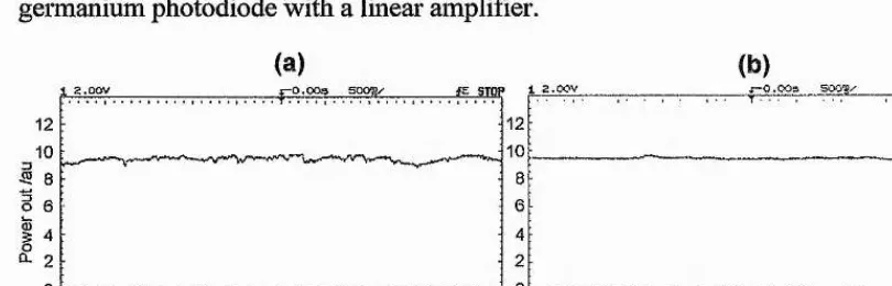
The most straightforward method of measuring an optical pulse is with a broadband photodiode and a fast oscilloscope. Unfortunately, while photodiodes with bandwidths as broad as 100 GHz have been developed, the real-time oscilloscopes are limited to bandwidths <1 GHz. Thus for pulses less than ~1 ns in duration, this direct detection method merely seiwes to monitor the amplitude noise of the individual pulses in the modelocked sequence, no information about the actual pulse duration may be inferred from this measurement.
resolving pulses shorter than ~20 ps, an electron-optical streak camera is suitable.
The electron-optical streak camera
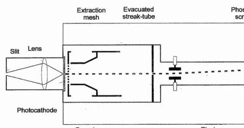
For the typical pulses obtained from a synchronously-modelocked NaChOH" laser (chapter 3) and the actively-modelocked diode-pumped Nd:YAG laser described in chapter 2, a Photochron II synchroscan streak camera with an SI photocathode was used (figure 1.1). Modem SI photocathodes have useful sensitivity to light at wavelengths out to -1.5 pm.
The streak camera is essentially an imaging tube with electrostatic deflector plates to sweep the image across the phosphor screen®®. Light incident on the slit is imaged onto the photocathode which converts the photons into an electron beam. This electron beam may be swept across the phosphor screen creating a streaked image of the entr ance slit. If an optical pulse is incident on the slit, a packet of electrons is liberated corresponding to the temporal pulse profile. When this packet is swept across the screen, an intensity profile of the pulse is created as a streak of light, provided that the static image (before the deflection signal is applied) is sufficiently smaller than the streaked image.
For optimum temporal resolution, the electrons liberated by the photocathode should have identical energies (and hence velocities) to minimise transit-time dispersion. This is optimal when the energy of the incident light is close to the long- wavelength cut-off of the photocathode: the long-wavelength cut-off depends upon the work-function of the photocathode material. For photon energies greater than the photocathode work-function, the emitted photelectrons are not monoenergetic due to the electron-hole generation mechanism and lattice scattering processes. This results in a distribution of initial photoelectron energies between zero and h v-E (where e is the
Extraction
mesh streak-tubeEvacuated Phosphorscreen
Slit
Photocathode
Streak trace Electron
beam Focusing
[image:22.613.93.485.65.270.2]cone Anode Deflectorplates
FIGURE 1.1: Schematic o f the Photochron II streak camera
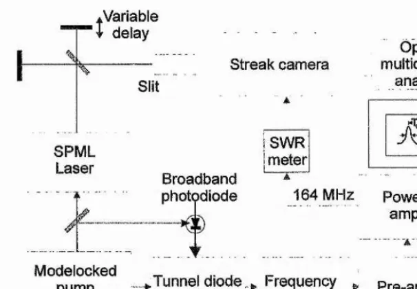
With periodic pulse sequences, such as those obtained from cw modelocked lasers, it is convenient to operate the streak camera with the deflector plates driven repetitively in synchronisation with the modelocked pulses enabling a real-time trace of the pulse profile to be displayed on an optical multichannel analyser (OMA) or equivalent. This mode of operation, termed ‘synchroscan’^” increases the dynamic range of the streak camera but unfortunately, because the trace results from an integration over thousands of modelocked pulses, the temporal resolution is limited to ~1 ps (in the case of a Photochron IV streak tube”') due to optical pulse jitter and jitter in the deflector drive electronics.
^Variable
I
delaySPML Laser
Modelocked pump
laser
Streak camera Slit
Broadband photodiode
SWR meter
Optical multichannel
analyser
164 MHz Power
amp
[image:23.612.137.440.69.279.2]^Tunnel diode _ Frequency ^ Pre-amp oscillator doubler
FIGURE 1.2: Schematic o f the synchroscan drive electronics, as used with the SPML laser described in
chapter S, The variable delay permits calibration o f the OMA.
1.3.2 Nonlinear pulse measurement techniques
The second-harmonic generation autocorrelator
The dilemma with creating veiy short events, such as the ultrashort pulses obtained from self-modelocked lasers, is that an even shorter event is required to characterise them. Since modelocked pulses are the shortest man-made events possible, the ultrashort pulse must be used to measure itself. One approach to achieving this utilises the second-order autocorrelation function of the modelocked pulse generated by a second-harmonic generation autocorrelator, first reported in the mid 1960’s”^. This effectively translates the problem of measuring a small time interval into one of measuring the distance a pulse propagates in that time interval, which is straightforward given the speed of light.
pulses so the autocorrelation trace is superimposed on a non-zero background signal resulting in poor contrast. Background-free intensity autocorrelation traces are possible using either collinear type II phasematcbing, where the two delayed pulses are of orthogonal polarisation, or non-collinear type I phasematcbing, where the two beams are laterally displaced but cross over in the SHG crystal. For both of these cases, a second-harmonic signal is only generated when an optical signal is present simultaneously in both beams, thus making it easier to determine if the modelocked pulse is superimposed on a pedestal or cw background.
Variable delay
SHG box
Photomultiplier tube
Fixed delay
Beam splitter Silicon
filter Fundamental sHG Lens
i k
FIGURE 1.3; Schematic o f the second-harmonic generation (SHG) autocorrelator (collinear with type I phasematcbing).
~ r)'dt
= 1 + 2 —— --- Equation (1.1)
X
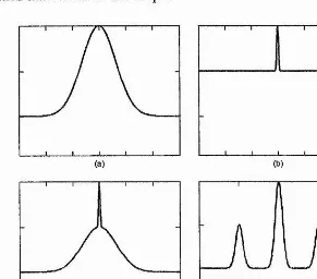
is the delay between the two pulses and I(t) describes the temporal intensity profile of a pulse in the modelocked pulse sequence. From equation 1.1 it can be seen that for delays outwith the extent of the modelocked pulse duration Tp, G^(T»Tp)==l because I(T»Tp)=0, whereas if the two pulses overlap, G^(0)=3. Thus the autocorrelation trace for a completely modelocked laser has a value of 3:1 from the peak of the outline to the background level (figure 1.4(a)). For a free-running multiple longitudinal mode (cw, not modelocked) laser, G^(0)=3 as the cw light will conelate with itself at zero delay. However, for delays greater than the coherence time of the light, the autocorrelation trace will result from a time averaging of the incoherent liglit: G^(x»Tp)=2 given that I(T»Tp)î*0. Thus a cw multi-axial-mode laser has an autocorrelation trace with a ratio of 3:2 (figure 1.4(b)). The width of the coherence spike corresponds to the coherence time of the laser light. In the case of a partially modelocked pulse or noise burst, the trace will have a broad pedestal of ratio 2:1 coiTesponding to the width of the noise burst envelope. Superimposed on top of this will be a coherence spike whose width corresponds to the coherence time of the substructure of the noise bur st (figure 1.4(c)). This type of trace is typically seen with unstabilised synchronously-modelocked lasers which operate with excessive bandwidth. Often, a modelocked laser may exhibit multiple pulsing, which may occur when the intracavity dispersion compensation is not optimised for the high intracavity power. This results in an autocorrelation trace with 2N-1 peaks where N corresponds to the number of output pulses per round trip (shown in figure 1.4(d) for N=2).The autocorrelator used throughout this thesis used a crystal of Li:Nb0 3 of
either 1 mm or 200 pm thickness, for SHG. This does not restrict the measurement to pulses with bandwidths less than the phasematcbing bandwidth of the crystal, provided that the pulses are unchirped^^: only the central carrier frequency is required for second-harmonic generation and as this is constant throughout the envelope of an unchirped pulse, the phasematcbing bandwidth can be quite narrow.
reti'oreflectors were used as the two minors in the Michelson interferometer. To obtain a real-time autocorrelation trace, the variable-delay reflector was mounted on a moving-coil loudspeaker driven with a triangular-waveform at a frequency ~20 Hz. The autoconelator delay is calibrated by translating the second mirror (mounted on a micrometer translation stage) by a known distance and measuring the time shift of the autocorrelation trace on the oscilloscope.
(a) (b)
[image:26.613.150.441.195.451.2](c) (d)
FIGURE 1.4: Intensity autocorrelations obtainedfor different laser operating conditions, (a) Completely
modelocked laser, (b) free-running cw-laser with multiple longitudinal modes oscillating out-of-phase.
(c) Partially modelocked laser/noise burst, (d) Modelocked laser operating with multiple pulses.
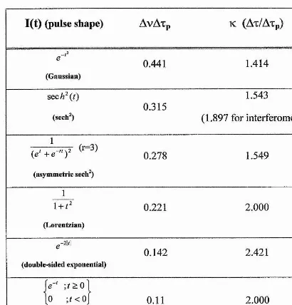
One drawback of the second-harmonic autocorrelation technique is that no precise information about the pulse shape is available from the symmetrical trace. The pulse duration may be deduced from an intensity autocorrelation trace (as in figure 1.4(a)) by assuming a pulse shape and dividing the autocorrelation full-width at half-maximum (FWHM) by a factor, ‘k’ , corresponding to that pulse shape (in
I(t) (pulse shape)
AvAxp
K(Ax/Axp)
e - ’
0.441
1.414
(Gaussian)
SQCh^(t)
0.315
1.543
(sech^)
(1.897 for interferometric)
( e ' + 7 " ) ^ '
0.278
1.549
(asymmetric sech^)
1
l + f2
0.221
2.000
(Lorentzian)
^-21/1
0.142
2.421
(double-sided exponential)
je-' ;f2:0l
[O
;t<0\
0.11
2.000
(single-sided exponential)
TABLE 1.1: Theoretical time-bandwidth products and correction factors for intensity autocorrelation measurements for different pulse-shapes.
By increasing the frequency response of the photomultiplier detector shown in figure 1.3, it is possible to resolve the interference between the individual optical cycles of the modelocked pulses as the delay is varied. A ‘fringe resolved’ autocorrelation takes the form of the second-order autocorrelation function given by:
Equation (1.2)
where the electric field of the pulse is described by:
, Equation (1.3)
[image:27.612.76.486.63.491.2]which conveys additional information regarding the frequency chirp present on a pulse. This is because a variation of the instantaneous phase over the duration of the pulse will reduce interference of the delayed pulses and hence reduce fringe visibihty at the wings or centre of the interferometric trace. An additional advantage of an interferometiic trace is that it is self calibrating: the fringe separation corresponds to one optical cycle at the centre wavelength of the pulse. Unfortunately, erroneous pulse duration measurements will be deduced from this type of autocorrelation if chirp is present. Note that the factor ‘k’ for deducing the pulse duiation from the autocorrelation trace is different for interferometric traces (table 1.1). In practice, interferometric autocorrelation traces were obtained by impedance-matching the photomultiplier-tube with the oscilloscope using a terminating resistor of ~5 kQ.
Recently, there have been several impressive demonstrations of the exploitation of the two-photon absorption effect in a light detector, to replace both the second- harmonic generating ciystal and the photomultiplier tube^'^’^^’®®. Detection devices as inexpensive and simple as a light-emitting diode^^ (LED) have been demonstrated to produce interferometric autocorrelation traces with a collinear style Michelson interferometer. InGaAs^® and silicon photodiodes®^ have also been utilised in such a scheme. The basic requirement is that the bandgap energy of the semiconductor is greater than wavelength of the light emitted by the laser. The photodetector is used photovoltaically so any potential difference appearing across the junction of the diode must arise from a two-photon absorption effect (TPA). This involves exciting the valence band electrons to a virtual energy level with one photon of the laser light. A second photon is required to promote this electron into the conduction band. The response of this effect has a quadratic dependence on the intensity of the incident light, hence its ability to replace the SHG crystal and photodetector in a second-order autocorrelator.
Advanced pulse characterisation techniques
produced from lasers in which self-phase-modulation is a major pulse shaping mechanism (e.g. self-modelocked systems) as this pulse shape is a solution to the nonlinear Schrôdinger equation’®. Nevertheless, advanced diagnostic systems have been demonstrated which allow complete characterisation of ultrashort pulses.
Normally a nonlinear optical element is used to act as a time-gate to sample segments of the optical pulse. This can involve second-harmonic generation or Kerr- based effects. Because a nonlinear process is involved, recovery of the original pulse requires an iterative algorithm which can be computationally intense.
An example of such a diagnostic technique, called fr equency-resolved optical- gating’' (FROG), involves a nonlinear autocorrelator (such as the SHG system in figure 1.3) which acts as a thne-gate. The resulting (e.g. SHG) signal is passed through a spectrometer, which allows a sonogram of the pulse to be constructed, by taking the variable delay of the autocorrelator into account. Using a suitable iterative algorithm, the complete pulse phase and spectral information can be reconstructed.
1.3.3 Spectral analysis of the modelocked pulse sequence
The optical spectrum of a modelocked laser provides useful information regarding the operating status of the laser. The spectral bandwidth is useful in determining the pulse shape, and whether the modelocked pulse is duration-bandwidth limited. In addition, it immediately shows whether the modelocked pulse is superimposed on a cw background signal by the presence of a cw spike.
factor of 16 (im would be necessary to account for the finite thickness of the dielectric coatings’^. The ffee-spectral-range is given by:
FSR(v)
= —^ Equation (1.4)2 •
d
and hence the bandwidth FWHM of the pulse can be measured from a storage oscilloscope.
1.4 Ultrashort Pulse Propagation
In designing laser sources capable of producing the shortest optical pulses, it is important that botii the broad optical spectra associated with the modelocked pulses, and their strong peak electric field strength are given careful consideration as both give rise to interesting phenomena.
1.4.1 Pulse propagation in linear dielectric media
An ultrashort pulse propagating in a linear dielectric medium will become distorted owing to the frequency dependence of the linear electrical-susceptibility tensor This results in a frequency dependence of the velocity of light propagating in the medium, which causes a modelocked pulse with a broad optical spectrum to stretch.
One way of expressing the frequency dependence of the refractive index of a medium is with an empirical Sellmeier equation:®
(o))
-1 = ■ Equation (1.5)C0„ -C D
(Oe is an effective resonant frequency of the material of relative strength A.
The material dispersion may be expressed by a Taylor expansion of the propagation constant p(co) defined by:
j8{co) ~
— ♦n{cd)
Equation (1.6)about the central carrier frequency mo:®
p{Cù) = '{ ( 0 - ( D ^ f -V ■ {cO - (O^f
Equation (1,7)
where the apostrophe signifies differentiation with respect to m.
The terms in equation 1.7 have the following physical significance:
P{
o)
q)
= — ■ «(^o)c
— = --- --- — Equation (1.8)phase velocity
P’{
g)
q)
= - • («(<yo) + • w'(cuo))c
— = --- — — Equation (1.9) Vg group velocityP"{
o)
q)
= — (2 ' n'(<^o) + g>
q •n'XcOo))
group-velocity dispersion (GVD) Equation (1.10)c
P”{
cO
q ) = i • (3 • w"(6)o ) + (Uq • )) third-order dispersion (TOD) Equation (1.11)c
The central carrier frequency, mo, of a modelocked pulse propagates at the phase velocity, v^, through the medium, but the pulse envelope itself propagates at the group velocity Vg. For an ultrashort pulse with a broad bandwidth propagating in a medium with a non-zero group-velocity dispersion, implying that the group velocity changes with frequency, the pulse envelope will change shape (broaden or compress). It is more usual to express GVD as a function of the wavelength derivative of the material’s refractive index:
P \
cO
q ) = — ^ Equation (1.12)For an initially unchirped Gaussian pulse, the pulse duration (Xpo) will be increased by a factor of V2 on propagation through the medium for a distance of: ®
= Equation (1.13)
T /(z ) = 1 +
V
pQ .
Equation (1.14) From equation 1.13 and using values pertinent to fused silica, it is apparent that the dispersion length is of the order of 1 m for 1 ps pulses but just 1 cm for pulses of-100 fs in duration. The gain medium in a laser is often of this length and so for lasers to produce sub-picosecond pulses it is important to compensate for this intracavity material GVD. For the even shorter pulse durations currently being reported by some research groups'* (<20 fs), the thiid-order dispersion (TOD) becomes increasingly important and must be taken into account.
1.4.2 Non-resonant Optical Nonlinearities
The high optical intensities available since the development of the laser have enabled certain nonlinear phenomena associated with optical materials to be accessed. These phenomena may be classified into resonant nonlinearities, which occur in materials exhibiting absorption at or close to the applied optical signal (e.g. incident radiation having a photon energy equal to the bandgap of a semiconductor sample), or non-resonant nonlinearities which are present
m
all transparent dielectric optical materials. An example of the former type is the gain experienced by a synchronously- modelocked laser pulse in the SPML NaChOET laser described in chapter 3, however, in general these are not important in the understanding of self-modelocked lasers where gain saturation does not play an impoitant role. Non-resonant nonlinearities are important as they give rise to a number of effects which are crucial to the understanding and optimisation of a femtosecond laser.For applied optical signals having strong electric fields, higher-order terms for the electrical susceptibility tensor must be included in the expression for the polarisation induced in a transparent dielectric medium (defined as net electric dipole moment per unit volume)®:
P
= ^oZ(i) • E +X(i) '
E^ +Z(
3)
• E^ Equation (1.15)The second-order nonlinearity term (x(2>) is non-zero only for materials based on a
crystal structure which does not possess inversion symmetry i.e. those materials which are also piezoelectric e.g. urea. This is responsible for second-harmonic generation (SHG) and for three-wave mixing in optical parametric oscillators. Apart from the use of the SHG effect to provide the auxiliary light for the NaChOH" laser (see chapter 3) second-order nonlinearities were not exploited for this work.
The thii'd-order nonlinearity term is non-zero for all dielectric materials but it becomes significant only for light beams with extremely strong electric fields such as those obtained by a tightly focussed beam from a modelocked laser. It is responsible for a number of phenomena including: third-harmonic generation, Raman scattering, Brillouin scattering and the Kerr-effect. This last effect is exploited in modelocked lasers resulting in spectral and spatial modification of the intracavity beam.
The Kerr-effect
If a sufficiently strong DC electric field is applied to a transparent dielectric medium, the non-zero X(3) value in equation 1.15 results in a dependence of the
refractive index of the material on the electiic field strength®:
« = «0 + Equation (1.17)
Eo describes the applied electric field and «ie is the Kerr coefficient (typically n2E^1 0‘^^ m^V'^). For a material with a positive D2e, the electric field causes an increase
in the refractive index for optical fields polarised parallel to the applied DC field Eo, but a decrease in the refractive index for fields polarised perpendicular to Eq. Thus a birefringence is induced in the material which may be used with crossed polarisers in a Kerr-cell modulator to induce an amplitude modulation on the optical field.
Normally the electric fields required to achieve appreciable modulation are very high (-lOO’s kV/cm^) but if the applied optical signal is of sufficient strength, the electric field associated witii the optical signal itself may incite a change in the refractive index of the material. This is termed the ‘optical Kerr-effect’. Equation 1.17 is then expressed as:
« = Wq + «2/ * 7 Equation (1.18)
electric field strength of the optical signal by:
/ =
f
.
Equation (1.19)This has an important effect both in the spatial and temporal domains for a femtosecond laser pulse propagating in a transparent dielectric medium.
Self-focusing of high intensity Gaussian beams
The smootli transverse profile of a Gaussian beam induces a spatial variation in the refractive index of a dielectric medium, according to equation 1.16: for a positive H21, the refractive index will be greater in the centre (peak) o f the beam than in the
wings of the beam profile thus creating a graded-index lens whose strength depends on the intensity of the overall beam. For the special case of an optical pulse propagating tlirough a medium, the induced nonlinear-lens will have a time dependence, being strongest at the peak of the pulse and weakest in the wings. It will be shown later that this time-dependent lens is exploited in self-modelocked lasers to create a synthetic fast saturable absorber.
Self-phase modulation (SPM)
For an ultiashort pulse propagating inside a dielectric medium having a positive
021, the refractive index of the material will gradually increase, reaching a maximum at
the peak of the pulse before decaying back to its original value after the trailing edge. The material effectively becomes optically longer during the leading edge of the pulse, thus the airival of the optical cycles is delayed. Conversely, during the trailing edge of the pulse, the material becomes gradually optically shorter hence the arrival of the optical cycles is advanced. Consequently, for a pulse propagating through a medium of length L, a net phase shift results which is given by®:
. Equation (1.20)
X
A positively chirped pulse results if H21 is positive -that is- the pulse leading edge is
results in a broadening of the optical spectmm of the pulse: the time-bandwidth product increases by a factor of V2 on propagating through a length L of material, if its peak intensity satisfies:
/ = ---- ^ . Equation (1.21)
In the special case of a pulse propagating in a nonlinear material and experiencing negative (anomalous) GVD, the positive chirp induced by the spectral broadening effect of SPM could be compensated by the anomalous GVD of the material; hence a shorter, duration-bandwidth limited pulse may result from an initially broader pulse by the interplay of SPM and GVD in a nonlineai* medium. This enables soldons to propagate inside optical fibres possessing anomalous group-velocity dispersion: the initial pulse coupled into the fibre is continually broadened spectrally by SPM and subsequently compressed by negative GVD until a final steady-state pulse shape is attained, limited only by higher-order dispersive and nonlinear effects. The resulting pulse does not then change shape on further propagation in the optical fibre provided that there is no loss™. This final pulse shape depends on the initial pulse energy where higher energies result in shorter pulse durations.
1.4.3 Ultrashort Pulse Propagation in a Resonator
In an actual laser resonator, both self-phase modulation (SPM) and group-velocity dispersion (GVD) co-exist, and together control the final pulse duration obtained from the laser™.
The intracavity elements contribute to the overall cavity GVD -that is- the gain medium, any modelocking devices (e.g. acousto-optic modulators) and the dielectric mirror coatings. In general, this GVD will be positive. Additionally, the tight focus present inside the vibronic gain medium of a tunable laser induces considerable self phase modulation which effectively generates the equivalent phase shift as would be produced by positive GVD. Without any compensation for this excessive positive GVD, the modelocked pulse durations would be severely limited by equation 1.11 to the order of 1 ps.
prisms with very low insertion loss. Such an arrangement is illustiated in figure 1.5. Chromatic dispersion at prism 1 causes the incident beam to spread by an angle
0.
This results in a path difference, before reconstruction by prism 2, dependent on thewavelength of the light component. Consideration of the geometry of figure 1.5 allows an expression for the effective GVD contribution to be derived: the second derivative of the optical path length of the prism sequence with wavelength is:
sin ^ - 2| - ^ 1 cos
0
Equation (1.22)t
is the prism apex separation, n is the index of refraction of the prism material,X
is the wavelength and P is the optical path length. The GVD contiibuted by the geometry of this system may be calculated with (jftom re-arranging equation 1.1 0):=
Equation (1.23)27VC CIA
Similarly, the material GVD contribution of the prisms and other inhacavity elements, may be calculated as:
g 3 y 2
1-L.
Equation (1.24)iToP
Here L refers to the physical length of material through which the beam passes.
Equation 1.22 is simplified by making the assumption that cos 0 is unity, and
C
sin
0 is approximated to twice the spot size at the first prism.long
[image:37.612.186.390.62.298.2]short
FIGURE 1.5: Prism sequence having negative overall group-velocity dispersion.
For the generation of the shortest pulses, third-order dispersion (TOD) becomes important. In a prism GVD compensated cavity this has two sources: the material contribution by all the intracavity elements and the geometrical contribution by the prism separation. Careful selection of the prism material is essential to minimise total TOD: by balancing the intraprism path length of the intracavity beam with the prism separation, overall TOD and GVD may be set to zero, provided that both contributions are of opposite signs^®’’^.
A simple model to describe how the GVD and SPM balance to produce a modelocked pulse of a certain duration is based on a soliton propagating inside an optical fibre^°. In the soliton model both the dispersion and the nonlinearity are considered to occur simultaneously inside the resonator. O f course, this is not physically realistic: the SPM occurs only inside the gain/nonlinear medium whereas the dispersion appears principally between the compensating prisms. However, this assumption is valid provided that the total cavity round-trip length within the dispersive elements is
less than the dispersive (Ld) and nonlinear lengths (Lnl) defined by:
Equation (1.25)
■'NL 1
E
■n
Equation (1.26)E is the pulse energy, Weff refers to the effective beam radius inside the nonlinear medium. This model is only strictly valid for pulse durations -100 fs or greater as for pulses considerably shorter than this, the discrete nature of the separate SPM and GVD sources becomes important. The possible order solitons from this model are given by the relationship:
^ 2 _ Equation (1.27)
^NL
Hence for the lowest order (N=l) soliton, a relationship between dispersion, pulse energy and pulse duration can be derived:
tpQ
= A •— —
Equation (1.28)From this expression, it can be seen that the pulse duration is inversely proportional to the pulse energy. Additionally, it is proportional to the square of the effective beam waist, hence a small reduction in the beam waist should have a considerable effect on the modelocked pulse duration. This is important in reducing the modelocking threshold of a laser, discussed in chapter 5.
1.5 Summary
The basic techniques appropriate to the design and operation of active and passive modelocked lasers have been outlined in this chapter. The key procedures employed throughout the work discussed in this thesis to characterise ultrashort pulses, have also been described. The effects of chromatic dispersion on ultrashort pulse propagation and the nonlinear effects associated with high peak optical powers, have been discussed in the context that is relevant to the behaviour of a modelocked laser cavity.
References
1 A.L. Schawlow and C.H. Townes,
Phys. Rev.
112,1940 (1958) 2 T.H. Maiman,Nature
187, 493 (1960)3 H.W. Messenger,
Laser Focus World
30
No.10,
Editorial p5 (1994)4 I.D. Jung, F.X. Kartner, N. Matuschek, D.H. Sutter, F. Morier-Genoud, Z. Shi, V. Scheuer, M. Tisch, T. Tschudi and U. Keller,
Appl Phys. B 65,
137 (1997)5 P.M.W. French, private communication at LEGS meeting on ultrafast physics, Glasgow 1997
6 A.E. Siegman in
Lasers,
(University Science Books, Mill Valley, California) 19867 H.A. Haus,
J Appl Phys
46,
3049 (1975)8 G.H.C. New,
Rep. Prog. Phys.
46,
877 (1983)9 D. J. Kuizenga and A. E. Siegman,
lEEEJ. Quantum Electron,
QE-6, p694 (1970)10 P.T. Ho, L.A. Glasser, E.P. Ippen, H.A> Haus,
Appl Phys. Lett.
33,
241 (1978) 11 L.A. Glasser,Electron. Lett.
14,
725 (1978)12 H. Kawaguchi and A.K. Sarwar,
Appl Phys. Lett.
62,
2164 (1993)13 P. Langlois, D. Gay, N. McCarthy and M. Piché,
Opt. Lett.
23 , 114 (1998) 14 H. Statz and C.L. Tang,J. Appl Phys.
36,
3923 (1965)15 G.H.C. New,
Rep. Prog Phys
46,
877 (1983) 16 G.R. Huggett,Appl Phys. Lett.
13, 186 (1968)17 D.E. Spence, J.M. Evans, W.E. Sleat and W. Sibbett,
Opt. Lett.
17,
1762 (1991) 18 E.P. Ippen, C.V. Shank and A. Dienes,Appl Phys. Lett.
21, 348 (1972)19 G.H.C. New,
Opt. Commun.
6,188 (1972)20 R.L. Fork, B.I. Greene and C.V. Shank,
Appl Phys. Lett.
38, 671 (1981) 21 A. Finch, G. Chen, W.E.D. Sleat and W. Sibbett,J. Mod. Opt.
35,
345 (1988) 22 J.Q. Bi, W. Hodel and H.P. Weber,Opt. Commun.
89, 240 (1992)26 C. Speilniann, F. Krausz, E. Wintner and A J. Schmidt in
Digest of the Topical
Meeting on Ultrafast Phenomena
(Optical Society of America, Washington, D C.,1990), paper PDIO
27 J.K. Chee, E.C. Cheung, M.N. Kong and J.M. Liu in
Digest of the Topical Meeting
on Ultrafast Phenomena
(Optical Society of America, Washington, D.C., 1990), paper MA228 P.M.W. French, J.A.R. Williams and J.R. Taylor,
Opt. Lett.
14, 6 8 6 (1989)29 C.P. Yakymyshyn, J.F. Pinto and C.R. Pollock,
Opt. Lett.
14, 621 (1989) 30 A. Sennaroglu, T.J. Carrig and C.R. Pollock,Opt. Lett.
17,
553 (1992)31 P.M. Mitschke and L.F. Mollenauer,
IEEE J. Quantum Electron.
QE-22, 2242 (1986)32 D.E. Spence, P.N. Kean and W. Sibbett,
Opt. Lett.
16,42 (1991)33 D.K. Negus, L. Spinelli, N. Goldblatt and G. Feugnet in
Advanced Solid-State
Lasers Topical Meeting Vol. 10 OSA Proceedings Series
(Optical Society of America, Washington, D.C., 1991) pl2034 F. Salin, J. Squier and M. Piché,
Opt. Lett.
16, 1674 (1991) 35 M. Piché,Opt. Commun.
8 6, 156 (1991)36 J. Herrmann,
J. Opt. Soc. Am. B , \ l ,
498, (1994) 37 F. Salin and J. Squier,Opt. Lett.
17, 1352 (1992)38 V. Magni, G. Cerullo and S. De Silvestii,
Opt. Commun.
96,348 (1993) 39 V. Magni, G. Cemllo and S. De Silvestri,Opt. Commun.
101,365 (1993) 40 G. Cerullo, S. De Silvestri, V. Magni, and L. Pallai'o,Opt. Lett.
19, 807 (1994) 41 G. Cerullo, S. De Silvestri and V. Magni,Opt. Lett.
19,1040 (1994)42 V. Magni, G. Cerullo S. De Silvestri and A. Monguzzi,
J. Opt. Soc. Am. B
12, 476 (1995)43 N. Sarukura, Y. Ishida, T. Yanagawa and N. Nakano,
Appl. Phys. Lett.
57, 229 (1990)44 N.H. Rizvi, P.M.W. French and J.R. Taylor,
Opt. Lett.
17,
279 (1992)46 Examples of commercial self-modelocked Ti:Sapphire systems are the Tsunami system from Spectra-Physics, Mountain View, CA USA, and the Mfra from Coherent, Santa Clara, CA USA
47 A. Miller, P. Li Kam Wa, B.H.T. Chai and E.W. Van Stryland,
O
pt. Lett.
17, 195 (1992)48 V.P. Yanovsky, F.W. Wise, A. Cassanho and H.P. Jensenn,
Opt. Lett.
20, 1304 (1995)49 K.X. Liu, C.J. Flood, D.R. Walker and H.M. van Driel,
Opt. Lett.
17, 1361 (1992) 50 G.P.A. Malcolm and A.L Ferguson,Opt. Lett.
16,1967 (1991)51 A. Seas, V. Petricevic and R.R. Alfano,
Opt. Lett.
17, 937 (1992) 52 A. Sennaroglu, C. R. Pollock, and H. Nathel,Opt. Lett.
19, p390 (1994) 53 G.T. Kennedy, R.S. Grant and W. Sibbett,Opt. Lett.
18, 1736 (1993) 54 Y.-F. Chou, K.-L. Deng and J. Wang,Opt. Lett.
18,1247 (1993)55 G. Gabetta, D. Huang, J. Jacobson, M. Ramaswammy, H.A. Haus, E.P. Ippen and J. Fujimoto, in
Technical Digest o f Conference on Lasers and Electro-Optics
(Optical Society of America, Washington D.C. 1991) paper CPDP856 K.A. Stankov and J. Jethwa,
Opt. Commun.
6 6, 41 (1988)57 G. Cerullo, V. Magni and A. Monguzzi,
Opt. Lett.
17, 1785 (1995)58 R. DeSalvo, D.J. Hagan, M. Sheik-Bahae, G. Stegeman and E.W. Van Stryland,
Opt.
Le/r. 17,28 (1992)
59 D.J. Bradley, B. Liddy, W.E. Sleat,
Opt. Commun.
2, 391 (1971)60 W. Sibbett,
Proc. XVth international conference on high speed photography and
photonics, SPIE
21,226 (1982)61 A. Finch, Y. Liu, W.E. Sleat, W. Sibbett and G. Chen,
Proc XVIIIth international
conference on high speed photography and photonics, SPIE
1032,
97 (1988)62 H.P. Weber,
J. Appl. Phys.
38,
2231 (1967)63 A.M. Weiner, ÆJEE J.
Quantum Electron.
QE-19, 1276 (1983)65 H.K. Tsang, L.Y. Chan, J.B.D. Soole, H.P. Leblanc, M.A. Koza and R. Bhat,
Electron. Lett.
31, 1773 (1995)6 6 A.M. Georgievski and S.V. Zaitsev,
Instrum.
&Exper. Techniques
39,117 (1996)67 D.T. Reid, M. Padgett, C. McGowan, W.E. Sleat and W. Sibbett,
Opt. Lett.
22, 233 (1997)6 8 C. McGowan, D.T. Reid, M. Ebrahimzadeh and W. Sibbett,
Opt. Commun.
134, 186(1997)
69 L.P. Barry, P.G. Bollond, J.M. Dudley, J.D. Harvey and R. Leonhardt,
Electron.
Lett.
32,1922 (1996)70 G.P.
AgndiSN&lm Nonlinear Fiber Optics
(Academic Press, London 1995) 71 D.J. Kane and R. Trebino,lEEEJ. Quantum Electron.
29, 571 (1993) 72 R.S. Grant, Ph.D. Thesis, University of St. Andrews (1991)73 O.E. Martinez, R.L. Fork and J.P. Gordon,