973
©IJRASET: All Rights are Reserved
Comparative Study of Deflection Behavior of RCC
and Pre-stressed Concrete Beams
Zeeshan Adib Ahmed
1, Dr. S. H. Mahure
21, 2 Department of Civil Engineering, Babasaheb Naik College of Engineering, Pusad, Maharashtra, India 1M.E. Final Year Student, 2Professor and Head of the Department
Abstract:Serviceability of a structure is generally defined as the clients' acceptance for continuous use of the structure for its lifetime under given loading condition without fear or any inhabitation. In reinforced concrete or prestressed concrete structures, cracking and deflection under service loads define the confident use of the structure at a given point of time. The deflections of structures are important for ensuring that the designed structure is not excessively flexible. The large deformations in the structures can cause damage or cracking of non-structural elements. Increased use of high strength concrete with reinforcing bars and prestressed reinforcement, coupled with more precise computer-aided limit state serviceability designs, has resulted in lighter and more material-efficient structural elements and systems. This in turn has necessitated better control of short-term and long term behavior of concrete structures at service loads.
In this study deflection behavior of R.C.C and prestressed concrete beams is studied through computer software STAAD.Pro and PROKON.The analysis is done for beams spanning 15m with variable spacing of 4m, 5m and 6m for R.C.C and prestressed concrete beams. Then the same model is analyzed with the consideration of one secondary beam at the center of primary beam and then two equally spaced secondary beams. Finally, one and two floating columns are placed over the primary beams with and without secondary so as to check the deflection behavior. All the values of deflection are compared with the permissible values as per Indian Standard code. The aim is to compare the results with the permissible values and also to determine the percentage change in deflection for similar conditions of RCC and prestressed concrete beams.
Keywords: Serviceability of a structure, Prestressed Concrete, R.C.C, deflection, Computer aided Analysis
I. INTRODUCTION
Wide availability of personal computers and design software, plus the use of higher strength concrete with steel reinforcement has permitted more material efficient reinforced concrete designs producing shallower sections. More prevalent use of high-strength concrete results in smaller sections, having less stiffness that can result in larger deflections. Consequently, control of short-term and long-term deflection has become more critical. In many structures, deflection rather than stress limitation is the controlling factor. Deflection computations determine the proportioning of many of the structural system elements. Member stiffness is also a function of short-term and long-term behavior of the concrete.
Excessive deflection of beams and slabs causes cracking of finishes, loss of strength of members, improper drainage and unsightly appearance. Sometimes, the excessive sag may be visually unacceptable.
IS 456 (2000) Clause 23.2 and BS 8110 limit allowable deflection under service loads as follows:
1) The deflection in the members due to all causes (namely. loads as well as effects of temperature, creep. shrinkage. etc.) should not exceed span/250.
2) The deflection which will take place after completion of the main construction (including erection of partitions and applications of finishes) due to long-term effects of the permanent loads (i.e. due to creep and shrinkage) together with the deflection due to the transient load (that pan of applied load which is applied and removed intermittently) should not exceed span/ 350 according to IS 456 and span/500 according to BS 8110 or 20 mm. whichever is less.
The first condition refers to the deflection that can be noticed by the eye and the second condition is to prevent damages to the finishes. The empirical method to limit deflection is to limit span/depth ratio as given in IS 456 Clause 23.2.1. However, in marginal casts and in the case of special structures, deflection may have to be calculated.
II. MODELINGANDANALYSIS
974
©IJRASET: All Rights are Reserved
computed and compared. This was followed by the introduction of floating columns over the primary beams and tabulation of results was done.
In next stage of analysis, prestressed beam was modeled using PROKON software. Load was applied over the beam and deflection was measured for the particular span and loading.This process was again followed with an introduction of floating columns. At last again a comparison was made for all the cases.
A. Modeling for Various Cases
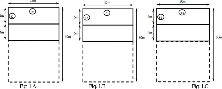
[image:2.595.78.507.308.480.2]The modelling was done for RCC and prestressed beam spanning 15m.As stated, modelling for all RCC cases was done using STAAD.Pro software while PROKON software’s CAPTAIN module was used for analysis of Prestressed concrete beams. Initially RCC beam spanning 15m was modelled and calculated load was assigned over its span as per the value for spacing of 4m.Then the spacing was varied upto 6m and accordingly results were tabulated. Then the same model is analyzed with the consideration of one secondary beam at the center of primary beam and then two equally spaced secondary beams. Finally, one and two floating columns are placed over the primary beams with and without secondary beams in case of R.C.C frame and floating columns are placed over prestressed beams so as to check the deflection behavior. All the values of deflection are compared with the permissible values as per Indian Standard code
Fig. 1.A Fig. 1.B Fig. 1.C
[image:2.595.77.496.523.713.2]Fig.1: Typical plan configurations for RCC and Prestressed beam spanning 15 m and spacing 4m (Fig. 1A), 5m(Fig.1B) and 6m(Fig.1C)
Fig. 2.A Fig. 2.B Fig. 2.C
975
©IJRASET: All Rights are Reserved
Fig.3: Typical plan configurations for RCC and Prestressed beam and one floating column spanning 15 m and spacing 4m (Fig. 3A),5m(Fig.3B) and 6m (Fig.3C)
Fig.4: Typical plan configurations for RCC and Prestressed beam and one floating column spanning 15 m with one secondary beam at centre and spacing 4m (Fig. 4A),5m(Fig.4B) and 6m (Fig.4C)
Fig.5: Typical plan configurations for RCC beamsspanning 15 m with two secondary beams (equally spaced) and spacing 4m (Fig.5),5m(Fig.5B) and 6m (Fig.5C)
976
©IJRASET: All Rights are Reserved
Fig.7: Typical plan configurations for RCC beam and Prestressed and two floating columns spanning 15 m with two secondary beam(equally spaced and spacing 4m (Fig. 7A),5m(Fig.7B) and 6m (Fig.7C)
B. Assumed Data
1) Number of Stories: G+4
2) Story Height = 5m
C. Sample Load Calculation
Load Calculations for RCC beam spanning 15 m and spacing 5m (Ref. fig 1B) 1) Load on Beam B1
a) Load from slab:
i) Self-Wt. of slab = 0.15 m x 25 KN/m3= 3.75 KN/m2
ii) Live Load = 5 KN/m2 … [assumed]
iii) Total Load = 8.75 KN/m2
b) Load from slab acting on beam = 2x(qlx/2) = qlx = 8.75 x 5 = 43.75KN/m … [Since one way slab]
c) Self-Wt. of Beam = 0.7mx 0.8m x 25 KN/m3 =14KN/m
d) Total Load = 58 KN/m≈ 60 KN/m
e) Factored Load =1.5 x Total Load = 1.5 x 60 = 90KN/m
2) Load on Beam B2 a) Load from slab
i) Self-Wt. of slab = 0.15 m x 25 KN/m3= 3.75 KN/m2
ii) Live Load = 5 KN/m2 … [assumed]
iii) Total Load = 8.75 KN/m2
b) Load from slab acting on beam = qlx/3 = (8.75 x 5) /3= 14.60 KN/m … [Since one way slab]
c) Self-Wt. of Beam = 0.23mx 0.8m x 25 KN/m3 =4.6 KN/m
d) Wt. of Brick Masonry = 0.23m x5m x 20 KN/m3 = 23 KN/m
e) Total Load = 42.2 KN/m
f) Factored Load =1.5 x Total Load = 1.5 x 42.2=63.3≈ 65KN/m
Sr.
No. Name of Structural Member
Dimension (Width X Depth)
01 Size of primary beam (i.e. Beam with span
ranging from 15m to 20m) 0.7m X 0.8m
02 Size of secondary beam (i.e. Beam with span
ranging from 4m to 6m) 0.23m X 0.8m
03 Size of Columns supporting beams 0.75mX0.75m
04 Size of Floating Columns 0.23m X 0.6m
05 Depth of Slab 0.15m
977
©IJRASET: All Rights are Reserved
III.RESULTANDDISCUSSION
Modelling of RCC and Prestressed concrete beam was done for the following cases as mentioned in Table 1 and Table 2. The effect of deflection was studied for primary beam by the introduction of one and two secondary beams, one and two floating column and both at a same time. Deflection values were obtained using computer software STAAD.Pro (for RCC beams) and PROKON-CAPTAIN (for Prestressed beams).Load was calculated separately for each case and was applied accordingly before analysis execution. The obtained values of deflection were compared with the permissible values.
[image:5.595.47.551.231.739.2]A. Deflection Results for RCC Beam
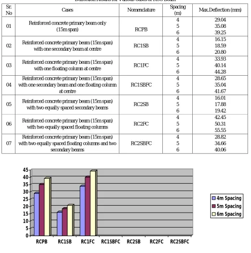
TABLE I
Deflection Results for Various Cases of RCC Beam
0 5 10 15 20 25 30 35 40 45
RCPB RC1SB RC1FC RC1SBFC RC2SB RC2FC RC2SBFC
4m Spacing 5m Spacing 6m Spacing
GRAPH 1:VARIOUS CASES OF RCCBEAM VS.DEFLECTION
Sr.
No Cases Nomenclature
Spacing
(m) Max.Deflection (mm)
01 Reinforced concrete primary beam only
(15m span) RCPB
4 5 6 29.04 35.08 39.25
02 Reinforced concrete primary beam (15m span)
with one secondary beam at centre RC1SB
4 5 6 16.15 18.59 20.80
03 Reinforced concrete primary beam (15m span)
with one floating column at centre RC1FC
4 5 6 33.93 40.14 44.28 04
Reinforced concrete primary beam (15m span) with one secondary beam and one floating column
at centre RC1SBFC 4 5 6 28.65 35.04 41.67
05 Reinforced concrete primary beam (15m span)
with two equally spaced secondary beams RC2SB
4 5 6 16.01 17.88 19.42
06 Reinforced concrete primary beam (15m span)
with two equally spaced floating columns RC2FC
4 5 6 42.45 50.31 55.55 07
Reinforced concrete primary beam (15m span) with two equally spaced floating columns and two
978
©IJRASET: All Rights are Reserved
B. Deflection Results for Prestressed Concrete Beam
[image:6.595.50.544.217.550.2]Prestressed Concrete beam of 15 m span was assigned load as per calculated values depending upon variable spacing of primary beam. For the sake of comparison, number of cables and depth of beam was kept constant and finally the obtained values of deflection were tabulated. Here, in case of prestressing, four cables each containing 19 strands of 15.2mm diameter i.e 7-3mm wires in each strand with cable area of 140mm2 was used. The ultimate strength of cable was assumed to be 260.7 kN.
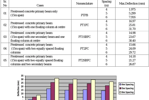
TABLE 2
Deflection Results for Various Cases of PRESTRESSED BEAM
0 5 10 15 20 25 30 35
PTPB PT1FC PT1SBFC PT2FC PT2SBFC
Prestressed Concrete Beam Cases
D e fl e ct io n ( m m ) 4m Spacing 5m Spacing 6m Spacing
Graph 2: Various Cases of Prestressed Beam Vs. Deflection
C. Permissible Values of deflection: 1) Span/250=60 mm
2) Span/350=42.85 mm
Since very small value of deflection was observed in Case ‘PTPB’ hence no effect of secondary beam was considered as already deflection was within permissible values and introduction of secondary beam(s) would further reduce deflection due to revised loading over primary beam. This study highlights the amount to which deflection value will increase by the increment of load due to variable transverse spacing of primary beam , effect of deflection due to floating column over transfer girder and hence control of the same by the introduction of secondary beam ,using prestressing and combined effect of both secondary beam and floating column.
Sr.
No Cases Nomenclature
Spacing
(m) Max.Deflection (mm)
01 Prestressed concrete primary beam only
(15m span) PTPB
4 5 6 1.975 5.299 7.916
02 Prestressed concrete primary beam
(15m span) with one floating column at centre PT1FC
4 5 6 16.97 25.81 31.70 03
Prestressed concrete primary beam
(15m span) with one secondary beam and one floating column at centre
PT1SBFC 4 5 6 14.98 23.67 30.40 04
Prestressed concrete primary beam
(15m span) with two equally spaced floating columns PT2FC 4 5 6 15.66 24.09 29.72 05
Prestressed concrete primary beam (15m span) with two equally spaced floating columns and two secondary beams
979
©IJRASET: All Rights are Reserved
IV.CONCLUSIONS
1) For a constant span and variable spacing, as the spacing of primary beam increased, consistently deflection also increased.
2) For 15m span value of deflection for all cases was found to be within the permissible by criteria span/250 but in some cases like RC1FC-6m and RC2FC-5m&6m the deflection value exceeded the permissible value by criteria span/350.
3) As compared to RCC primary beam, deflection of prestressed primary concrete beam has decreased by about 93.19%, 84.89% and 79.83% for 4m, 5m and 6m spacing respectively.
4) As compared to RCC beam with one floating column at centre, the deflection of prestressed concrete primary beam with one floating column at centre has decreased by 49.98%, 42.23% and 37.07% for 4m, 5m and 6m spacing respectively.
5) As compared to RCC beam with one secondary beam and one floating column at center, the deflection of prestressed concrete primary beam with one secondary beam and one floating column at center has decreased by 40.28%, 33.51% and 33.21% for 4m, 5m and 6m spacing respectively.
6) As compared to RCC beam with two equally spaced floating columns, the deflection of prestressed concrete primary beam with two equally spaced floating columns has decreased by 78.96%, 77.27% and 76.13% for 4m, 5m and 6m spacing respectively.
7) As compared to RCC beam with two equally spaced floating columns and two secondary beams, the deflection of prestressed concrete primary beam with two equally spaced floating columns and two secondary beams has decreased by 43.15%, 39.46% and 38.87% for 4m, 5m and 6m spacing respectively.
REFERENCES
[1] Hemant Belsare., Suchitra De & Shraddha Sharma “ Economics of Continuous RCC and Prestressed Concrete beam and design in MS-Excel” , International Journal of Innovations in Engineering and Technology, vol.7, Issue 2 August 2016.
[2] A. R. Mundhada & Mohmmad Shahezad “Economics of continuous R.C.C. Beams Vis-à-vis Continuous Pre- Stressed Concrete Beams”, International journal of Scientific & Engineering Research, volume 3, Issue 7, July 2012
[3] Vakas K.Rahman & Prof. A.R. Mundhada “ Comparative study of R.C.C. and Prestressed Concrete Flat Slab”, International Journal of Modern Engineering Research (IJMER), Vol. 3, Issue. 3, May.-June. 2013 pp-1727-1730
[4] Anthony J.Wolanski “Flexural Behavior Of Reinforced And Prestressed Concrete Beams Using Finite Element Analysis” M.Tech Thesis.
[5] Dr. S.H.Mahure & Mr.Vishal D. Dhore, “Comparative Study of RCC And Prestressed Concrete Beams For Various Spans” IJSART - Volume 3 Issue 9 – SEPT. 2017
[6] Mr.Vishal D. Dhore ,Dr. S.H.Mahure “Comparative Study of R.C.C. and Prestressed Concrete One Way Continuous Slab for various spans”, International Journal For Engineering Applications and Technology, vol 3 Issue 9
[7] Sukumar Behera (2012), “Seismic analysis of multistory building with Floating Column”, Department of Civil Engineering NIT, Rourkela- 769008 May 2012. [8] Shaheenjaham, Akshata C Sureban, Megha Chappalagaon, Mudassar Sharif, “Comparative Study on Design of RCC and PSC Beams”, International Journal of
Advanced Research in Science, Engineering and Technology Vol. 3, Issue 6 , June 2016
[9] Rajamoori Arun Kumar, B. Vamsi Krishna, “Design of Pre-Stressed Concrete T-Beams” International Journal of Scientific Engineering and Research (IJSER), Volume 2 Issue 8, August 2014
[10] M.K.Maroliya “Comparative study of Flexural behavior of Reinforced Concrete Beam and Prestressed Concrete Beam”, International Journal of Engineering Research and Applications, Vol. 2, Issue 6, November-December 2012, pp.230-233
[11] V. Kavitha , K.P. Nandhini, P.Prakash, Dr.N.Arunachalam “Economical Design of Prestressed Concrete Beams” , International Journal of Innovative Research in Science, Engineering and Technology, Vol.5, Issue3, March 2016.
[12] Ankit Sahu, Prof. Anubhav Rai, Prof. Y.K. Bajpai “Cost Comparison Between Rcc & Post-Tensioned Prestressed Beams Spanning 26m”, International Journal of Computational Engineering Research (IJCER), Vol.4, Issue6, June 2014
[13] Lin, T.Y, and NED H BURNS “Prestressed Concrete”, Third Edition, John Wiley & Sons [ASIA] Pt e Ltd., Singapore 129809. [14] N. Krishna Raju, (2007). “Prestressed Concrete”, Fourth Edition, Tata McGraw- Hill Company Ltd., New Delhi.
[15] B.N Dutta, (2009) “Estimating and Costing In Civil Engineering”, Twenty- Sixth Revised Edition UBS Publishers’ Distributors Pvt. Ltd. New Delhi. [16] “Control of Deflection in Concrete Structures” (Reapproved 2000), ACI 435R-95, American Concrete Institute,
[17] “Code for Structural use of concrete” BS 8110-1:1997, Standards Board of publication, BSI