Optical trapping with a perfect vortex beam
Mingzhou Chen
a, Michael Mazilu
a, Yoshihiko Arita
a, Ewan M. Wright
band Kishan Dholakia
aa
SUPA, School of Physics & Astronomy, University of St Andrews, North Haugh, St Andrews,
KY16 9SS, United Kingdom;
b
College of Optical Sciences, The University of Arizona, 1630 East University Boulevard,
Tuscon, Arizona 85721-0094, USA
ABSTRACT
Vortex beams with different topological charge usually have different profiles and radii of peak intensity. This introduces a degree of complexity the fair study of the nature of optical OAM (orbital angular momentum). To avoid this, we introduced a new approach by creating a perfect vortex beam using an annular illuminating beam with a fixed intensity profile on an SLM that imposes a chosen topological charge. The radial intensity profile of such an experimentally created perfect vortex beam is independent to any given integer value of its topological charge. The well-defined OAM density in such a perfect vortex beam is probed by trapping microscope particles. The rotation rate of a trapped necklace of particles is measured for both integer and non-integer topological charge. Experimental results agree with the theoretical prediction. With the flexibility of our approach, local OAM density can be corrected insituto overcome the problem of trapping the particle in the intensity hotspots. The correction of local OAM density in the perfect vortex beam therefore enables a single trapped particle to move along the vortex ring at a constant angular velocity that is independent of the azimuthal position. Due to its particular nature, the perfect vortex beam may be applied to other studies in optical trapping of particles, atoms or quantum gases.
Keywords: Optical Trapping, perfect vortex, Orbital Angular Momentum (OAM)
1. INTRODUCTION
In the optical domain, an optical vortex beam may possess orbital angular momentum (OAM) 1 which is
attributable to the helical wavefront of the beam. The number of interwinding helices (or the number of 2πphase changes around the beam axis) is corresponding to the topological charge`. Such a vortex beam typically has a radial dependence upon the value of the topological charge.2–4 There have been a number of approaches to control
the spatial property of a vortex beam using the Laguerre-Gaussian (LG) modes and high-order Bessel beams. In particular, Schmits andet. al.5 demonstrated the unchanged beam profile for different`by interfering the two
oppositely charged vortex beams. However, because of interference of the two beams, intensity modulation on the ring was unavoidable. ˇCiˇzm´aret. al. implemented an incoherent mode superposition to demonstrate smooth tuning of the OAM density6 with intensity variations though the use of an acousto-optic deflector may cause unwanted aberrations. In the context of all of these studies, a vortex beam with a fixed profile and continuous tuneable OAM density would be of significant interest.
The concept of a ‘perfect optical vortex’ was first introduced in Ref.7 denoting a vortex field whose intensity
CCD i
CW Laser 1070nm, 5W
Axicon
Mirror
L
L2
P1
L3
MO
L4
L5
TP
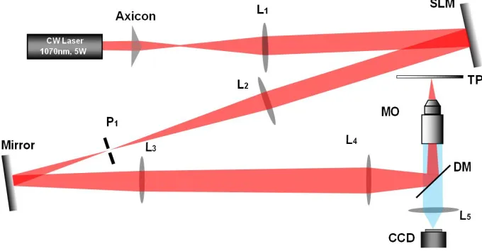
[image:2.612.135.475.73.250.2]CCD
Figure 1. Optical setup used for trapping with a perfect vortex beam.
2. EXPERIMENTAL SETUP AND BEAM CORRECTION
In the experimental setup as shown in Fig. 1, an axicon (apex angle is 178◦) together with a lens (L1) provide
a ring illumination on the spatial light modulator (Hamamatsu LCOS-SLM X10468-03). In contrast to usually taking its Fourier transform, the SLM plane is directly imaged onto the trapping plane (TP) with lenses L2 ∼ L4and a microscope objective (M O, Nikon, 40X, NA=1.3, oil). The modulated first diffraction order is selected
by a pinhole (P1). A dichroic mirror (DM) reflects the laser while transmitting the illumination light. The
standard part of LED white light illumination used to illuminate the trapping plane is not shown in the Fig. 1 while the optical path is shown by the blue beam.
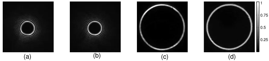
The topological charge of the beam is controlled by the vortex phase together with a grating phase applied on the SLM. The achievable topological charge is mainly constrained by the back aperture of M Odue to the ring illumination used. In our system, we can realise topological charges ranging from`=−40 to +40. As most of optical aberrations in the system is attributable to the flatness of SLM surface, they can be corrected effectively by applying a well-known wavefront correction method.9 As examples shown by Fig.2 (a) and (b), the beam
quality is improved after wavefront correction on SLM.
After wavefront correction, there are still some intensity hot spots in the beam profile (Fig. 2 (c)), which may cause the particles to be trapped in these local intensity maxima. Recalling the SLM is on the image plane of trapping plane and it is a phase-only one, we can remove these intensity hot spots locally by reducing the local efficiency of phase modulation at the locations of hot spots. After such an intensity profile correction, the intensity uniformity of the beam is significantly improved as can be seen in Fig. 2 (d).
3. PARTICLES TRAPPING WITH A PERFECT VORTEX BEAM
3.1 Trapping a necklace of particles
For the first studies, the created perfect vortex beam is filled with 26 polymer particles (3µm in diameter) to make a necklace as shown by Fig. 3 (a). This necklace of particles are rotating in two dimensions and pushed against the microscope coverslip surface of the water chamber. The roation of the particles can be dictated by the gradient and scattering forces resulting from the vortex beam.
To analyse the rotation rate of the particles, videos are recorded by a fast camera at a rate of 150 fps. We vary the topological charge ` from −35 to +35 in steps of 5. From positions of one trapped particle in each video frame, the orbital rotation rate of the necklace can be evaluated. As shown by the fitted lines in Fig. 3
0.25 0.5 0.75 1
[image:3.612.85.530.74.175.2](a) (b) (c) (d)
Figure 2. High order bessel beams (`= 20) on the focal plane of SLM before (a) and after (b) wavefront correction.Vortex beams (`= 20) on the trapping plane before (c) and after (d) amplitude correction.
Positive vortices y=0.032x−0.044 Negative vortices y=0.032x+0.046
(a)
(b)
−40 −20 20 40
−1.2 −0.8 −0.4 0.4 0.8 1.2
ℓ Rotation rate (Hz)
Figure 3. (a) A necklace of 26 polymer particles (3µmin diameter) trapped by a he perfect vortex beam`= 20. (b) The necklace rotation rate as a function of the integer topological charge`. Positive rotation rate is defined as anti-clockwise rotation. The solid lines represent a least-square linear regression of the original data.
(b), a linear relationship between the rotation rate and the topological charge of the perfect vortex beams can be clearly seen for both negative and positive topological charges due to the well-defined OAM density in each beam. The discontinuity near the origin (zero rotation rate) can be explained by the friction force between the particles and the glass coverslip.
Interestingly, the same approach is used to probe the OAM of vortex beams with a non-integer topological charge. With a necklace of 26 particles a collective ‘averaged’ rotation of the particle necklace can be observed. The rotation rate is measured when the necklace is rotating on a perfect vortex beam with the topological charge
`ranging from−12 to−9 and 9 to 12 in steps of ∆`= 0.2. The rotation rate does not vary linearly for fractional variations of the topological charge. However, it is in good agreement with the theoretical models,10 as shown
by the fitted soid lines in Fig. 4.
3.2 Single particle trapping
[image:3.612.85.530.215.367.2]−12 −11.5 −11 −10.5 −10 −9.5 −9 −0.4
−0.35 −0.3
Rotation rate (Hz)
ℓ
9 9.5 10 10.5 11 11.5 12
0.24 0.26 0.28 0.3 0.32 0.34 0.36 0.38
ℓ
Experimental data
y=0.032[x−sin(2πx)/2π]−0.022 Experimental data
y=0.032[x−sin(2πx)/2π]+0.024
[image:4.612.110.503.79.227.2](a) (b)
Figure 4. The particle rotation rate as a function of both positive (a) andthe necklace negative (b) fractional topological charge`. The solid lines with a specific prefactor and offset shows a least-square regression of the experimental data to the theoretical prediction of OAM per photon of a fractional vortex as `−sin(2π`)/(2π).10
−2 0 2 4
0 10 20 30 40 50 60
−3 −2 −1 0 1 2 3
0 0.5 1 1.5
Angular position on the ring (rad)
Angular speed (rad/s) Raw
Smoothed
(b)
(a) (c)
Figure 5. (a) a video frame of a single trapped particle. (b) Histogram of particle distribution along the radial direction on the vortex ring. (c) Angular speeed of the trapped partile along the vortex ring.
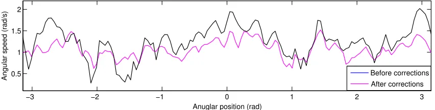
The variations in the angular speed of a single trapped particle in the perfect vortex beam can only be explained by the inpure orbital angular momentum state. This statement can be verified simply by a numerical simulation of optical force on a vortex ring as shown in Fig.6. A uniform optical force along the perfect vortex ring can only be achieved when the beam is in a pure orbital angular momentum state which in the perfect case corresponds to integer topological charge.
Based on the knowledge that the particle rotation velocity is linearly dependent upon the OAM density, the angular velocity can be adjusted locally by increasing or decreasing the local phase gradient. This adjustment can be realised by the SLM since it directly controls the phase of the vortex beam. Where the angular velocity
−3 −2 −1 0 1 2 3
35 40 45 50
Angular position (rad)
Optical force (a.u.)
ℓ= 10 ℓ= 10.3
[image:4.612.82.533.291.404.2] [image:4.612.99.516.582.672.2]−3 −2 −1 0 1 2 3 0.5
1 1.5 2
Anuglar position (rad)
Angular speed (rad/s) Before corrections
[image:5.612.93.519.77.185.2]After corrections
Figure 7. Angular speed of a single trapped particle on a perfect vortex beam.
is high, we can reduce the phase gradient and vice versa.
With the application of beam corrections discussed above, we can achieve smooth rotation speed for a single trapped particle on a perfect vortex beam, as shown in Fig. 7.
4. CONCLUSION
In conclusion, we introduce an approach for generating perfect vortex beams with a uniform intensity profile regardless of its topological charge. Phase, amplitude and local OAM density correction are applied in situ to achieve a smooth particle motion. Such a perfect vortex beam may be used for other applications including micromixing and moving microparticles on complex trajectories.
ACKNOWLEDGMENTS
The authors would like to thank the UK Engineering and Physical Sciences Research Council (EPSRC) for funding.
REFERENCES
[1] Allen, L., Beijersbergen, M. W., Spreeuw, R. C., and Woerdman, J. P., “Orbital angular momentum of light and the transformation of Laguerre-Gaussian laser modes,”Phys. Rev. A45, 8185–8189 (June 1992). [2] Simpson, N. B., Allen, L., and Padgett, M. J., “Optical tweezers and optical spanners with
Laguerre-Gaussian modes,”J. Mod. Opt.43(12), 2485–2492 (1996).
[3] Garc´es-Ch´avez, V., McGloin, D., Padgett, M. J., Dultz, W., Schmitzer, H., and Dholakia, K., “Observation of the transfer of the local angular momentum density of a multiringed light beam to an optically trapped particle,”Phys. Rev. Lett.91, 093602 (Aug 2003).
[4] Curtis, J. E. and Grier, D. G., “Structure of optical vortices,”Phys. Rev. Lett.90, 133901 (apr 2003). [5] Schmitz, C. H. J., Uhrig, K., Spatz, J. P., and Curtis, J. E., “Tuning the orbital angular momentum in
optical vortex beams,”Opt. Express14, 6604–6612 (jul 2006).
[6] ˇCiˇzm´ar, T., Dalgarno, H. I. C., Ashok, P. C., Gunn-Moore, F. J., and Dholakia, K., “Interference-free superposition of non-zero order light modes: functionalized optical landscapes,”Appl. Phys. Lett.98, 081114 (2011).
[7] Ostrovsky, A. S., Rickenstorff-Parrao, C., and Arriz´on, V., “Generation of the ”perfect” optical vortex using a liquid-crystal spatial light modulator,”Opt. Lett.38, 534–536 (feb 2013).
[8] Chen, M., Mazilu, M., Arita, Y., Wright, E. M., and Dholakia, K., “Dynamics of microparticles trapped in a perfect vortex beam,” Opt. Lett.38(22), 4919–4922 (2013).
[9] ˇCiˇzm´ar, T., Mazilu, M., and Dholakia, K., “In situ wavefront correction and its application to micromanip-ulation,”Nat. Photonics4, 388–394 (June 2010).