Compatibility at Junction Planes between Habit Plane Variants
with Internal Twin in Ti-Ni-Pd Shape Memory Alloy
Takeshi Teramoto
1,+1, Masaki Tahara
2, Hideki Hosoda
2and Tomonari Inamura
2,+21Department of Innovative and Engineered Materials, Tokyo Institute of Technology, Yokohama 226-8503, Japan 2Precision and Intelligence Laboratory, Tokyo Institute of Technology, Yokohama 226-8503, Japan
The kinematic compatibility (KC) between habit plane variants (HPVs) was numerically analyzed and classified in Ti-25Ni-25Pd alloy. There are six distinct types of HPV pair that can satisfy the KC condition at averaged junction plane (JP) between twinned HPVs. By analyzing the KC condition between lattice correspondence variants (CVs) in the HPVs, it was found that there are three types of HPV pair in which all the CVs can be compatible due to the existence of the common rotation to keep the KC at all JPs simultaneously. On the other hand, it was found that the incompatibility inevitably remains in the morphologies known as spear (wedge), folk and herring-bone.
[doi:10.2320/matertrans.MB201515]
(Received August 27, 2015; Accepted October 6, 2015; Published November 13, 2015)
Keywords: self-accommodation microstructure, kinematic compatibility, shape memory alloy, titanium-nickel-palladium
1. Introduction
As described in the phenomenological theory of martensite
crystallography (PTMC),16) the crystallography of the
isolated martensite plate is determined by the invariant plane (IP) condition at the habit plane that is the interface between the parent and the martensite phase. The martensite plate with
the invariant plane character is called “habit plane variant
(HPV)”. A HPV in shape memory alloys, in general, consists of two kinds of lattice correspondence variants (CVs). The
CV whose volume fraction is larger than 0.5 is termed“main
CV”, and the other is termed“sub CV”in this study. The sub
CV is introduced as the lattice invariant deformation (LID) to satisfy the IP condition at the habit plane.
In shape memory alloys, HPVs connect each other to cancel out the macroscopic change in shape and then
self-accommodation microstructure (SAM) is formed;7) the
connecting HPVs are termed“HPV cluster”, hereafter. Only
limited kinds of morphology appear in experiment, even though there are numerous kinds of HPV cluster in combination logic, depending on the number of HPVs forming the cluster. In cubic-orthorhombic martensitic trans-formation, the fork type microstructure and the spear type microstructure that are constructed by two HPVs are
observed in Ag-Cd.8)The triangular cluster and the diamond
cluster that are constructed by the three and four HPVs
respectively are observed in Ti-Ni-Cu9) and Cu-Al-Ni,10)
respectively.
The arithmetic average of the shape change matrix of HPVs in a cluster has been a guiding principle to evaluate the degree of self-accommodation and to predict the preferential
morphology.8,1116) The formation frequency of the HPV
clusters in experiment is, however, not always explained by the principle.1719)
The condition of connection between HPV is essential to consider the preferential morphology and geometry of the interfaces. The evaluation of the misfit at the junction plane
(JP) between HPVs is possible by using the kinematic
compatibility (KC) condition.20)Consider two domains each
with homogeneous deformation gradient (Ui and Uj). The
deformation becomes continuous across the interface be-tween the two domains only if the following equation has realistic solution forQij,aandn,21)whereas the deformation
gradient is discontinuous across the interface;
QijUjUi¼an ð1Þ
Qij is the additional rotation of Uj required for the KC
condition withUiat the interface.aandnare the vectors that
describe the difference between the shape change directions of the domains and the normal direction of the interface,
respectively. The rotation Qijis a measure of the
incompat-ibility at the interface.22,23)The effect of the incompatibility on HPV clusters is essential to understand the mechanism
of the formation of SAM,1719) except for a special alloy
where formation of a fully compatible microstructure is possible.2426)The HPV clusters with smallerQijare preferred
in the actual transformation.1719,22,23)
The cubic-orthorhombic martensitic transformation is one
of a major transformation in shape memory alloys.2731)
Saburi et al.9) proposed that the triangular morphology is
the preferential microstructure in Ti-Ni-Cu. In our previous
study on a¢-titanium shape memory alloy with¢(bcc)¹¡AA
(orthorhombic) martensitic transformation, two kinds of V-shape morphology and the triangle morphology have been
identified as the preferential HPV cluster by transmission
electron microscopy (TEM) observation and a theoretical evaluation of Qij.32,33) In these previous studies, the alloys
investigated had no LID and only twelve HPVs exist in theory. In general,{111}otype I twin or©211ªotype II exist as LID and there are twenty-four HPVs for a given mode of
LID in the cubic-orthorhombic martensite.4,6,34) The
classi-fication of HPV clusters byQijin the previous study32)does
not represent the general geometrical character of the HPV clusters in the cubic-orthorhombic transformation.
Figure 1 schematically shows HPV, averaged JP between HPVs and local JPs between CVs. The HPV that consists of the main CV ofiand the sub CV ofjis represented by{i,j} +1Graduate Student, Tokyo Institute of Technology
+2Corresponding author, E-mail: inamura.t.aa@m.titech.ac.jp
and is shown in Fig. 1(a). The HPV cluster consists of two HPVs ({i,j} and {k,l}) that are connected at JP. There are two kinds of characteristic interfaces. One is the averaged JP between HPVs (HPVJP) as shown in Fig. 1(b); we assume twinned HPVs as if they are homogeneous domains as treated in most of the previous studies.20,21)The other is the local JP
between CVs (CVJP) that is defined by considering the
inhomogeneous structure of HPV as shown in Fig. 1(c).
CVJP are classified into four groups as CVJP (main«main),
CVJP (sub«sub), CVJP (main«sub) and CVJP (sub«main) as
depicted in Fig. 1(c). Nishidaet al.17,18)and Inamuraet al.19) showed that the KC condition at the CVJP affects the formation frequency of HPV cluster in Ti-Ni. It is, therefore, essential to evaluate the KC condition not only at HPVJP but also at CVJP in an alloy that has LID to understand the underlying principle of the formation of SAM in the general cubic-orthorhombic martensite. Thorough analysis of the HPV clusters that are possible in combination logic among two HPVs is necessary. The analysis of CVJP has not been made, though the KC conditions at HPVJP in cubic-orthorhombic martensitic transformation has been theoret-ically analyzed by K.F. Haneet al.35)
The objective of this study is to reveal and classify the HPV clusters by the KC conditions at HPVJP and/or CVJPs with cubic-orthorhombic martensitic transformation with LID. The analysis is made using the lattice parameters of Ti-25Ni-25Pd alloy as a model alloy because analytical
solution is not obtained in general.21) An emphasis is on
finding the distinct pairs of HPVs in which HPVJP and
CVJPs are bring into compatible by a common rotation, because incompatibility is minimized in such clusters.19)
2. Experimental and Analysis Procedure 2.1 The notations and the lattice parameters
A Ti-25 mol%Ni-25 mol%Pd alloy was fabricated by Ar
arc-melting method (Ar+1%H2). The ingot was
homogen-ized at 1373 K for 21.6 ks. The homogenhomogen-ized ingot was
cold-rolled to be 20% reduction in thickness. The cold-rolled
specimen was wrapped in Ta foil, sealed in evacuated quartz tubes, annealed at 1373 K for 3.6 ks and then quenched by breaking the quartz tube in water. The surface of specimen
was chemical etched in a solution of 25% H2O+25%
HF+25% H2SO4+25% HNO3 at 363 K. ª-2ª XRD
analysis was performed at room temperature (RT, 298 K) and 523 K using an PANalytical X’pert Pro Galaxy system
equipped with an X’celerator module. CuK¡ radiation was
used and Si was the reference material utilized to correct systematic error in the diffraction profiles. Lattice parameters were obtained by a least-squares method on a PC
(CellCalc).36) The calculation was done in the bcc lattice
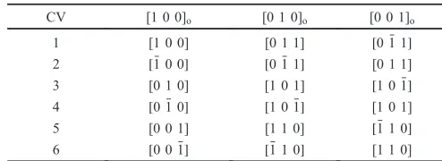
coordinate; the vectors without subscript is referred to the bcc (parent phase) lattice coordinate. The subscript“o”indicates the orthorhombic (martensite) lattice coordinate. In the Ti-Ni-Pd, the parent phase has the B2 and the martensite has the B19, and there are six CVs following the Au-Cd type lattice correspondence.28)The notation and the definition of CVs are given in Table 1.
The{111}otype I twin is introduced as the major LID in
each HPV and the habit plane is close to the{hkk}-type in Ti-25Ni-25Pd alloy as similar to other alloys that undergo the
cubic-orthorhombic martensitic transformation.2731) The
lattice parameters used for the analysis are a=306.3 pm,
ao=278.4 pm, bo=466.9 pm and co=444.6 pm,
respec-tively. The diagonalized deformation gradient of the lattice
deformation is diag{0.909, 1.078, 1.026}; the third
compo-nent is larger than unity and the IP condition is satisfied by
the LID of the{111}otype I twin in PTMC.34) The internal
twin as the LID has been experimentally revealed to be the
{111}o type I twin in the present alloy.37) The volume
fraction of the sub CV is 0.303 in PTMC.
2.2 The deformation gradient of HPV
The deformation gradient of the isolated HPV that satisfies the IP condition at the habit plane, namely the KC condition between a HPV and the parent phase, was calculated by the
geometrically non-linear theory of martensite (GNLTM).21)
The deformation gradient of{i,j},U{i,j}is calculated by the following equations;
QBjBi¼aInI ð2Þ
Ufi;jg¼Q0ðQBjþ ð1ÞBiÞ ¼Iþbhmh; ð3Þ
where Bi is the deformation gradient of the lattice
deformation of the i-th CV. aI and nI are the vectors that
describe the shear direction and the twinning-plane normal
of the relevant {111}o type I twin as LID. Q and QA are
additional rotations for the KC conditions. is the volume
Averaged HPV
HPVJP
i(Main CV)
j(Sub CV)
Averaged habit plane
(c) Local JPs between CVs (CVJP)
(b) Averaged JP between HPVs (HPVJP) (a) HPV
Main|Main-JP Sub|Sub-JP
Main|Sub-JP
{i,j} {k,l}
{i,j} {k,l}
{i,j}
Sub|Main-JP
[image:2.595.52.278.67.292.2]Fig. 1 Schematic diagram of HPV (a) and HPV cluster ((b) HPVJP (c) CVJP).
Table 1 Lattice correspondence.
CV [1 0 0]o [0 1 0]o [0 0 1]o
1 [1 0 0] [0 1 1] ½0 1 1
2 ½1 0 0 ½0 1 1 [0 1 1]
3 [0 1 0] [1 0 1] ½1 0 1
4 ½0 1 0 ½1 0 1 [1 0 1]
5 [0 0 1] [1 1 0] ½1 1 0
[image:2.595.301.548.83.173.2]fraction of thei-th CV (main CV) andIis the identity matrix.
bh and mh are the vectors that describe the shape change
direction and the habit plane normal, respectively. U{i,j} is
identical to the shape change matrix obtained by PTMC.21)
[image:3.595.47.290.93.397.2]Notice that U{i,j} is an averaged deformation gradient with neglecting the twinned microstructure of HPV. The notation of HPV and the corresponding habit plane are summarized in Table 2.
2.3 KC condition at HPVJP
The KC condition at HPVJP was evaluated by solving the following equation.
Qfi;jgfk;lgUfk;lgUfi;jg¼bHVmHV ð4Þ
Q{i,j}{k,l} is a rotation with rotation angle of ªHPV to make {k,l}to be compatible to{i,j}and,«ªHPV«is the indicator of the misfit at HPVJP.bHPVandmHPVare vectors that represent the difference of the shape change directions of the HPVs and the normal of the HPVJP, respectively.
2.4 KC condition at CVJP
The deformation gradients of CVs that form a HPV are no longer the pure lattice deformation because a small rotation
have been made to form the HPV with the IP character.16)
The deformation gradients of CVs (V) that form a HPV are
calculated by the product of the lattice deformation and the additional rotations in eqs. (2) and (3) as following.
Vi¼Q0Bi ð5Þ
Vj¼Q0QBj ð6Þ
Here,ViandVjare the deformation gradients of the main CV
and the sub CV that form the HPV. Then, the following equation is solved forbandnto evaluate the KC condition at CVJP.
Jfi;jgfk;lg
pq VqVp¼apqfi;jgfk;lgnfpqi;jgfk;lg ð7Þ
Jfi;jgfk;lg
pq is a rotation with the rotation angle of ºfpqi;jgfk;lg to make theq-th CV of{k,l}(q=korl) to be compatible to the p-th CV of{i,j}(p=iorj).jºfpqi;jgfk;lgjis an indicator of the misfit at the CVJP. apqfi;jgfk;lg and nfpqi;jgfk;lg are vectors that represents the twining direction and the normal of the CVJP (the twinning plane).
3. Results and Discussion
3.1 Overview of KC condition at HPVJP and CVJP
There are 24 identical HPVs and the total number of HPV cluster is 480 in the combination logic. Figure 2 shows the
classification of all the possible HPV clusters. The HPV
clusters that are shaded in Fig. 2 can satisfy the KC condition; eq. (4) has 288 realistic solutions that can be categorized into only six types as represented by the symbols I,II,III,IV,VandVI. In contrast to that the KC condition can
be satisfied between any HPVs and the HPV is doubly
degenerated when LID is absent,32) only the limited
combinations of HPVs can satisfy the KC condition at HPVJP when the LID exists. This is due to the existence of the sub CV as the LID and is the general situation in the cubic-orthorhombic martensite. The solutions of eq. (4), Q{i,j}{k,l},ªHPVand mHPV, for the pair-type ofI,II,III,IV,V
and VI in Fig. 2 are summarized for {1, 3} and {k,l} in
Table 3. There are two sets of solution for a given pair of HPVs. Roman numbers in the right side column is the solution number for the convenience. Following analysis for CVJP is given for these six pair-types.
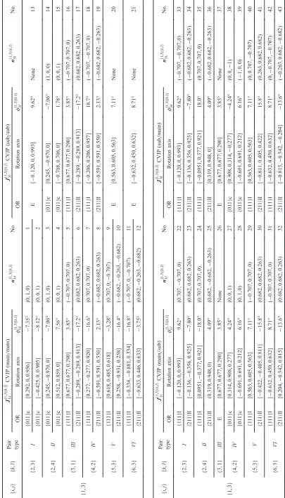
For the six pair-types shown in Table 3, the KC conditions
at CVJPs are summarized in Table 4. In the column ‘No.’,
solution number is newly given for the convenience. There
are specific twin relationships among the CVs.21) The
solutions whose nfpqi;jgfk;lg is rational and corresponding to
the twinning plane of {111}o type I twin are indicated as
‘{111}I’in the column named‘orientation relationship (OR)’ (No. 5, 7, 9, 11, 16, 18, 22, 24, 29, 31, 33, 35, 40 and 42). Similarly, the solutions corresponding to©211ªotype II twin are indicated as‘©211ªII’(No. 6, 8, 10, 12, 17, 19, 23, 25, 30, 32, 34, 36, 41 and 43). For the pairs of CVs that have rational
nfi;jgfk;lg
pq and afpqi;jgfk;lgare indicated by ‘{011}c’; the relevant twin relationship is{011}ocompound twin (No. 14, 1415, 2728 and 3839). OR of‘E’indicates that the CVs are the same across the JP and are brought into coincidence by the rotation (No. 13, 20, 21, 26 and 37).
There are six special solutions in which KC conditions
at HPVJP and/or CVJPs are simultaneously satisfied by a
common rotation to the advantage of reducing the incom-patibility and is discussed in detail in the following sections.
3.2 HPV cluster with fully compatible junction plane
Firstly, three solutions in which fully compatible con-nection of HPVs is possible are shown as depicted in Fig. 3.
For the solutions iii in Table 3, the geometry of the pair
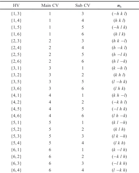
Table 2 Notation of HPV for Ti-25Ni-25Pd h=0.604, k=0.285, l= 0.744.
HV Main CV Sub CV nh
{1, 3} 1 3 (¹h k l)
{1, 4} 1 4 (h k l)
{1, 5} 1 5 (¹h l k)
{1, 6} 1 6 (h l k)
{2, 3} 2 3 (h k¹l)
{2, 4} 2 4 (h¹k l)
{2, 5} 2 5 (h¹l k)
{2, 6} 2 6 (h l¹k)
{3, 1} 3 1 (k¹h l)
{3, 2} 3 2 (k h l)
{3, 5} 3 5 (l¹h k)
{3, 6} 3 6 (l h k)
{4, 1} 4 1 (k h¹l)
{4, 2} 4 2 (¹k h l)
{4, 5} 4 5 (¹l h k)
{4, 6} 4 6 (l h¹k)
{5, 1} 5 1 (k l¹h)
{5, 2} 5 2 (k l h)
{5, 3} 5 3 (l k¹h)
{5, 4} 5 4 (l k h)
{6, 1} 6 1 (k¹l h)
{6, 2} 6 2 (¹k l h)
{6, 3} 6 3 (¹l k h)
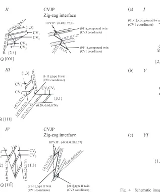
typeII viewed from [001] is schematically drawn in Fig. 3(a). In the solutions 3 and 14 in Table 4, the rotation
for the KC condition at CVJP (main«main) and CVJP
(sub«sub) are the same and is equal to the rotation for the
KC at HPVJP;Jf121;3gf2;4g¼J34f1;3gf2;4g¼Qf1;3gf2;4g. This means
that HPVJP, CVJP (main«main) and CVJP (sub«sub) can
be compatible simultaneously by the common rotation in
exchange for the KC at CVJP (main«sub) and CVJP
(sub«main) are incompatible. The configuration of CVs in
Fig. 3(a), therefore, achieves fully compatible junction plane. This structure is accomplished by the one-to-one connection between main CVs (CV1 and CV2) and the one-to-one connection between sub CVs (CV3 and CV4). LID twin
planes of {1, 3} and {2, 4}, CVJP (main«main) and CVJP
(sub«sub) are edge-on in [001] zone. The width of each CVs
can match completely and the geometry in the microstructure shown in Fig. 3(a) is constructible. Enlarged view of the encircled region in Fig. 3(a) is also shown. The HPVJP
becomes zig-zag morphology that is formed by the {011}
compound twins.
The solutions No. 5, 16, 26 and 37 in Table 4 correspond
to the solution v for the pair-type III in Table 3. The
geometry of this HPV cluster viewed from [111] is depicted
in Fig. 3(b). LID twin planes of{1, 3},{3, 1}and all CVJP
are edge on in Fig. 3(b). As seen in the Tables 3 and 4, the
rotations for the KC at CVJP (main«main), CVJP (sub«sub),
CVJP (main«sub) and CVJP (sub«main) have the relationship
Jf131;3gf3;1g¼Jf311;3gf3;1g¼Jf111;3gf3;1g¼Jf331;3gf3;1g. This means that all the junction planes can be compatible simultaneously by
the common rotation. In these solutions, CVJP (main«main)
and CVJP (sub«sub) are parallel each other because
n13f1;3gf3;1g¼n11f1;3gf3;1g. On the other hand, CVJP (main«sub)
and CVJP (sub«main) cannot be defined because the main CV
and the sub CV are the same CV in this case;nf11l;3gfk;lg and
nf1;3gfk;lg
3k have no solution in the solution No. 26 and 37
Table 4. The twin planes of the LID, the CVJPs and HPVJP
㻌 {1,3} {1,4} {1,5} {1,6} {2,3} {2,4} {2,5} {2,6} {3,1} {3,2} {3,5} {3,6} {4,1} {4,2} {4,5} {4,6} {5,1} {5,2} {5,3} {5,4} {6,1} {6,2} {6,3} {6,4}
{1,3} I II III IV V VI
{1,4} II I IV III VI V
{1,5} I II V VI III IV
{1,6} II I VI V IV III
{2,3} I II III IV VI V
{2,4} II I IV III V VI
{2,5} I II VI V III IV
{2,6} II I V VI IV III
{3,1} III IV I II V VI
{3,2} IV III II I VI V
{3,5} V VI I II III IV
{3,6} VI V II I IV III
{4,1} III IV I II VI V
{4,2} IV III II I V VI
{4,5} VI V I II III IV
{4,6} V VI II I IV III
{5,1} III IV V VI I II
{5,2} IV III VI V II I
{5,3} V VI III IV I II
{5,4} VI V IV III II I
{6,1} III IV VI V I II
{6,2} IV III V VI II I
{6,3} VI V III IV I II
{6,4} V VI IV III II I
{i,j}
{
k,l
}
[image:4.595.70.525.74.301.2]Fig. 2 Classification of all possible HPV cluster, shaded pair can satisfy the KC condition at HPVJP.
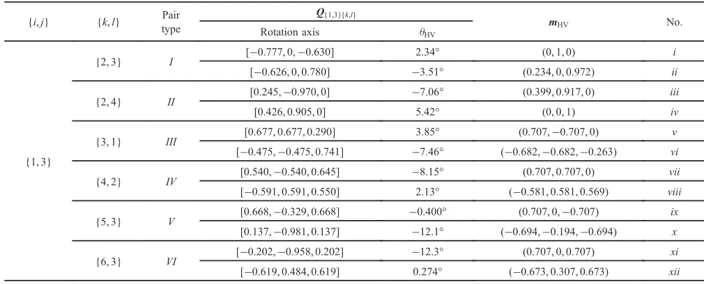
Table 3 Solutions for KC condition at HPVJP.
{i,j} {k,l} Pair
type
Q{1,3}{k,l}
mHV No.
Rotation axis ªHV
{1, 3}
{2, 3} I [¹0.777, 0,¹0.630] 2.34° (0, 1, 0) i
[¹0.626, 0, 0.780] ¹3.51° (0.234, 0, 0.972) ii
{2, 4} II [0.245,¹0.970, 0] ¹7.06° (0.399, 0.917, 0) iii
[0.426, 0.905, 0] 5.42° (0, 0, 1) iv
{3, 1} III [0.677, 0.677, 0.290] 3.85° (0.707,¹0.707, 0) v
[¹0.475,¹0.475, 0.741] ¹7.46° (¹0.682,¹0.682,¹0.263) vi
{4, 2} IV [0.540,¹0.540, 0.645] ¹8.15° (0.707, 0.707, 0) vii
[¹0.591, 0.591, 0.550] 2.13° (¹0.581, 0.581, 0.569) viii
{5, 3} V [0.668,¹0.329, 0.668] ¹0.400° (0.707, 0,¹0.707) ix
[0.137,¹0.981, 0.137] ¹12.1° (¹0.694,¹0.194,¹0.694) x
{6, 3} VI [¹0.202,¹0.958, 0.202] ¹12.3° (0.707, 0, 0.707) xi
[image:4.595.44.549.346.550.2]are (10). The KC condition at the junction planes can be kept completely in this HPV cluster.
The solutions No. 8 and 19 for CVJPs in Table 4 correspond to the solutionviiifor pair-typeIVin Table 3. In this pair, Qf1;3gf4;2g¼J14f1;3gf4;2g¼Jf321;3gf4;2g. This means that
the CVJP (main«main) and CVJP (sub«sub) can be compatible
simultaneously by the common rotation and then the HPVJP
between {1, 3} and {2, 4} also becomes compatible. The
geometry viewed from ½111 is schematically shown in
Fig. 3(c). This structure is formed by the one-to-one connections of main CVs (CV1 and CV4) and sub CVs
(CV3 and CV2) to eliminate the CVJP (main«sub) and CVJP
(sub«main). The twinning plane of LID, CVJP (main«main)
and CVJP (sub«sub) are edge-on. An enlarged image of the
encircled region of HPVJP is also shown. The CVs are
connected by ©211ªtype II twin orientation at the CVJPs in
this HPV cluster. The CVJPs form the zig-zag morphology as shown in Fig. 3(c) and the averaged interface normal
corresponds to the HPVJP of the solutionviiiof Table 3.
These three HPV clusters in Fig. 3 have fully compatible junction planes. Relevant twin orientations are held at CVJPs and the HPVJPs are simultaneously compatible. However, it should be noted that the KC condition between martensite and parent phase (invariant plane condition of habit plane) is not kept on the compatible connection of the HPVs because HPV(s) are rotated to make compatible junction plane; the
KC conditions at JPs and the KC conditions at habit planes are competitive. Incompatibility is always placed on some interfaces in general.
3.3 HPV cluster with incompatibility
There are another set of HPV clusters with much smallerQ
for the KC condition at HPVJP, even though some CVJPs cannot be compatible unlike the HPV clusters in the previous section. As shown below, these HPV clusters require very small rotation for the KC at HPVJP, whereas a higher incompatibility remains at CVJPs. As discussed later, it is
interesting that the common morphologies named
“dia-mond”,“wedge”, folk and“spear”8)in literatures are formed
by these HPV clusters.
The schematic image of the solution i for pair-typeI
viewed from [001] is shown in Fig. 4(a). LID twin planes of
{1, 3},{2, 3} and HPVJP are edge on in this image. In the
solutions No. 13, 22 and 33, the rotation for KC condition at
CVJP (sub«sub), CVJP (main«sub) and CVJP (sub«main) are
the same whereas it is different from Q{1,3}{2,3};J33f1;3gf2;3g¼
J13f1;3gf2;3g¼J32f1;3gf2;3g6¼Qf1;3gf2;3g. This means that that CVJP
(sub«sub), CVJP (main«sub) and CVJP (sub«main) can be
compatible simultaneously by the same rotation, in exchange
for the compatibility at CVJP (main«main) and HPVJP, and
vice versa. Figure 4(a) is drawn for the case where the
incompatibility is placed on the CVJP (main«main) and
HPVJP. The orientation relationship between the main CVs
(a)
(b)
(c)
V
VI
I
CV3CV1
CV2
CV3 HPVJP: (0,1,0)
{1,3}
{2,3}
(01-1)ocompound twin (CV1 coordinate)
[001]
{1,3} {5,3}
HPVJP: (0.71,0,-0.71)
(-0.
60,
0.
29,
0.
74)
CV1
CV3
CV5
CV3
(-111)otype I twin (CV1 coordinate)
[111]
{1,3} {6,3}
(-0.
74,
0.29,
0.
60)
CV3 CV1
CV3 CV6
(-0.
60,
0.
29,
0.
74)
HPVJP: (-0.67,0.31,0.67)
[211]otype II twin (CV1 coordinate)
[111]
Fig. 4 Schematic images of HPV cluster (I,VandVI), (image of CVJP represent dashed line circled area of HPV cluster).
III
{1,3}
{3,1}
CV1
CV3
CV3CV1
(0.29,-0.60,0.74)
IV
HPVJP : (-0.58,0.58,0.57)
{1,3} {4,2}
(-0.
60,
0.
29,0.
74)
(-0
.2
9,0
.6
0,0.7
4)
CV4
CV2
CV1
CV3
CVJP
Zig-zag interface
II CVJP
Zig-zag interface
{2,4}
{1,3}
HPVJP : (0.40,0.92,0)
CV4
CV2
CV1
CV3
(a)
(b)
(c)
(01-1)ocompound twin
(CV1 coordinate) (011)ocompound twin
(CV3 coordinate)
(1-11)otype I twin
(CV1 coordinate)
[21-1]otype II twin
(CV1 coordinate)
[211]otype II twin
(CV3 coordinate)
[111]
[111]
[001]
[image:6.595.67.384.58.437.2] [image:6.595.304.531.72.419.2]has a deviation from the {011} compound twin due to the incompatibility.
The solution ix in pair-typeV and solution xii in
pair-typeVI in Table 3 has ªHV of only 0.400° and 0.274°,
respectively. This means that the HPVJP becomes almost compatible in average when individually growing relevant HPVs that are satisfying the invariant plane condition of habit plane collide by chance. The schematic image of the HPV cluster for the solutionixfor pair-typeVviewed from [111] is
shown in Fig. 4(b). LID twin planes of {1, 3}, {5, 3} and
HPVJP are edge on in this image. The rotations for the KC
at CVJP (sub«sub), CVJP (main«sub) and CVJP (sub«main)
in the solutions No. 20, 29 and 40 for are common;
Jf1;3gf5;3g
33 ¼Jf131;3gf5;3g¼Jf351;3gf5;3g and are not equal to the
rotations for the KC at HPVJP and CVJP (main«main). These
results mean that CVJP (sub«sub), CVJP (main«sub) and
CVJP (sub«main) can be compatible simultaneously by the
common rotation and, then the CVJP (main«main) is
incompatible, or vice versa. Figure 4(b) is drawn as CVJP
(sub«sub), CVJP (main«sub) and CVJP (sub«main) being
compatible and CVJP (main«main) is incompatible. In this
case, there is a deviation of 3.28° from the{111}type-I twin orientation between main CVs across the HPVJP.
The morphology of HPV cluster corresponding to the solutionxiin the pair-typeVIviewed from½111is depicted in Fig. 4(c). LID twin planes of{1, 3}and{6, 3}are edge on
in this image. The rotations for KC at CVJP (sub«sub), CVJP
(main«sub) and CVJP (sub«main) in the solutions No. 21, 31 and 42 are the same;Jf331;3gf6;3g¼J13f1;3gf6;3g¼J36f1;3gf6;3gand are not equal to the rotations for KC at HPVJP and CVJP
(main«main). Therefore, CVJP (sub«sub), CVJP (main«sub)
and CVJP (sub«main) can be compatible simultaneously by
the common rotation in exchange of the incompatibility at
CVJP (main«main) and HPVJP, or vice versa. Figure 4(c) is
drawn for the case where the incompatibility is placed on CVJP (main«main). There is a deviation of 8.71° from©211ª type-II twin orientation between main CVs across the HPVJP.
3.4 Comparison with actual microstructure
A comparison between the present results and the actual
microstructure reported in literatures is briefly mentioned
here. Details of actual microstructure are also discussed elsewhere.38)
The six HPV clusters or relevant JPs found in this study are in good agreement with the observed microstructures in the actual transformations as mentioned in following.
As for the three HPV clusters with fully compatible
junction planes in Fig. 3, the “crossing twin”21,27) is
equivalent to the junction plane of pair-typeII in Fig. 3(a). The HPV cluster that is similar in morphology to the
pair-typeIVin Fig. 3(c) was observed in Ti-Nb-Al alloy.32) The
JP in pair-typeIIIin Fig. 3(b) is the{111}type-I twin and is the same twinning of the LID. These fully compatible HPV cluster or relevant JPs exist in the actual microstructure.
Well known morphology of HPV cluster in
cubic-orthorhombic martensitic transformation are the “spear
(wedge)”, “folk”,“herring-bone”and “diamond”.8,27,37) The folk, spear and herring-bone are equivalent to the HPV clusters in Fig. 4(a), Fig. 4(b) and Fig. 4(c), respectively.
In our latest study,38) spear, folk and herring-bone
micro-structure were observed in Ti-25 mol%Ni-25 mol%Pd.
Figure 5(a) is a brightfield image of the spear microstructure that is typical microstructure in cubic-orthorhombic
marten-sitic transformation. HPVJP was formed by{6, 1}and{4, 1}.
This HPVJP belongs to pair-typeV, according to Fig. 2.
A selected area electron diffraction (SAED) pattern and
diagrams are summarized in Figs. 5(b)(e). LID twin in
{6, 1} and {4, 1} was {111}o type I twin as indexed in
Figs. 5(c) and (d). Main«Main-JP was almost {111}o type I
twin as shown in Fig. 5(e). This microstructure is in good agreement with Fig. 4(b). The herring-bone in Fig. 4(c) has been reported in Ti-Au.27)
The diamond is formed by the coalescence of two spears and then the folk and herring-bone inevitably appears as demonstrated in our latest study.39)It should be pointed out that some of the CVJPs are not compatible, even though these are frequently observed in several alloys with
cubic-orthorhombic martensitic transformation such as Ti-Ni-Pd,37)
Ti-Pt,40)Ti-Pd,41) Ti-Au.27)The JPs on which the remained incompatibility is placed in the HPV clusters in Fig. 4 are not simply determined by the present analysis. The GNLTM analysis predicts the existence and the geometry of the incompatibility. In the actual microstructure, the incompat-ibility is placed at junction planes and/or habit plane and the interfacial energies that are not explicitly considered in the analysis play an important role. Precise orientation analysis at the junction planes is, therefore, necessary to reveal the place of the incompatibility in the actual microstructure.32)
4. Conclusions
The HPV clusters that are possible in combination logic
were classified in terms of the KC conditions at HPVJP and/
or CVJPs in Ti-25Ni-25Pd alloy and the results are summa-rized as follows.
There are six distinct types of HPV pair that can satisfy the KC condition at HPVJP (pair typeI,II,III,IV,Vand VI).
There are three types of HPV cluster that can form fully
compatible HPVJP and CVJPs (pair-typeII,IIIandIV). This
is originated to the existence of the common rotation that achieves the KC condition at all JPs simultaneously. However, the KC at habit plane is broken on the compatible connection
of HPVs. The CVs can be connected by{111}type-I,{011}
compound or©211ªtype-II twin orientation at CVJPs.
There are another set of three HPV clusters with much
smaller rotation for the KC condition at HPVJP (pair-typeI,
Vand VI), even though some CVJPs cannot be compatible.
These three HPV clusters are equivalent to the spear (wedge), folk and herring-bone morphologies. The twin orientation between CVs is not always held in these HPV cluster.
Acknowledgments
This work was partially supported by the Advanced Low Carbon Technology Research and Development Program (JY240121) from the Japan Science and Technology Agency,
Grant-in-Aid of Scientific Research (S: 26220907 and B:
REFERENCES
1) J. S. Bowles and J. K. Mackenzie:Acta Metall.2(1954) 129137. 2) J. K. Mackenzie and J. S. Bowles:Acta Metall.2(1954) 138147. 3) J. S. Bowles and J. K. Mackenzie:Acta Metall.2(1954) 224234. 4) J. K. Mackenzie and J. S. Bowles:Acta Metall.5(1957) 137149. 5) M. S. Wechsler, D. S. Lieberman and T. A. Read: Trans. AIME197
(1953) 15031515.
6) D. S. Lieberman, M. S. Wechsler and T. A. Read:J. Appl. Phys.26 (1955) 473484.
7) K. Otuska and C. M. Wayman (ed.): Shape Memory Materials, (Cambridge University Press, Cambridge, 1998).
8) T. Saburi and C. M. Wayman:Acta Metall.27(1979) 979995. 9) T. Saburi, Y. Watanabe and S. Nenno:ISIJ Int.29(1989) 405411. 10) S. Tan and H. Xu:Continuum Mech. Thermodyn.2(1990) 241244. 11) K. Otsuka and K. Shimizu:Trans. Jpn. Inst. Metals15(1974) 103108. 12) S. Miyazaki, K. Otsuka and C. M. Wayman:Acta Metall.37(1989)
18731884.
13) S. Miyazaki, K. Otsuka and C. M. Wayman:Acta Metall.37(1989) 18851890.
14) K. Madangopal:Acta Mater.45(1997) 53475365. 15) K. Otuska and X. Ren:Prog. Mater. Sci.50(2005) 511678. 16) M. Nishida, H. Ohgi, I. Itai, A. Chiba and K. Yamauchi:Acta Metall.
Mater.43(1995) 12291234.
17) M. Nishida, T. Nishiura, H. Kawano and T. Inamura:Philos. Mag.92 (2012) 22152233.
18) M. Nishida, E. Okunishi, T. Nishiura, H. Kawano, T. Inamura, S. Ii and T. Hara:Philos. Mag.92(2012) 22342246.
19) T. Inamura, T. Nishiura, H. Kawano, H. Hosoda and M. Nishida: Philos. Mag.92(2012) 22472263.
20) J. M. Ball and R. D. James:Arch. Rat. Mech. Anal.100(1987) 1352. 21) K. Bhattacharya: Microstructure of Martensite, (Oxford University
Press, Oxford, 2003).
22) J. M. Ball and D. Schryvers:J. Phys. IV112(2003) 159162.
23) X. Balandraud, D. Delpueyo, M. Grediac and G. Zanzotto:Acta Mater. 58(2010) 45594577.
24) Y. Song, X. Chen, V. Dabade, T. W. Shield and R. D. James:Nature 502(2013) 8588.
25) X. Chen, V. Srivastava, V. Dabade and R. D. James:J. Mech. Phys. Solids61(2013) 25662587.
26) A. Planes, L. Manosa and A. Saxena: Magnetism and Structure in Functional Materials, (Springer, 2005).
27) T. Inamura and H. Hosoda:Metall. Mater. Trans. A42(2011) 111120. 28) K. Morii, T. Ohba, K. Otsuka, H. Skamoto and K. Shimizu: Acta
Metall.39(1991) 27192725.
29) K. Otsuka, K. Oda, Y. Ueno, M. Piao, T. Ueki and H. Horikawa:Scr. Metall. Mater.29(1993) 13551358.
30) T. Biggs, M. J. Witcomb and L. A. Cornish:Mater. Sci. Eng. A273 275(1999) 204207.
31) A. R. G. Brown, D. Clark, J. Eastabrook and K. S. Jepson:Nature201 (1964) 914915.
32) T. Inamura, H. Hosoda and S. Miyazaki:Philos. Mag.93(2013) 618634. 33) T. Inamura, H. Y. Kim, H. Hosoda and S. Miyazaki:J. Alloy. Compd.
577S(2013) 592595.
34) T. Inamura, J. I. Kim, H. Y. Kim, H. Hosoda, K. Wakashima and S. Miyazaki:Philos. Mag.87(2007) 33253350.
35) K. F. Hane and T. W. Shield:J. Elasticity59(2000) 267318. 36) H. Miura: J. Crystallogr. Soc. Japan45(2003) 145147.
37) R. Delville, S. Kasinathan, Z. Zhang, J. V. Humbeeck, R. D. James and D. Schryvers:Philos. Mag.90(2010) 177195.
38) T. Teramoto, M. Tahara, H. Hosoda and T. Inamura: Mater. Today, in press.
39) T. Teramoto, M. Tahara, H. Hosoda and T. Inamura: MRS online proceedings library, in press.
40) M. Nishida, M. Matsuda, Y. Yasumoto, S. Yano, Y. Yamabe-Mitarai and T. Hara:Mater. Sci. Technol.24(2008) 884889.
41) M. Nishida, T. Hara, Y. Morizono, A. Ikeya, H. Kijima and A. Chiba: Acta Mater.45(1997) 48474853.
ZA : <1 1 0>o 500nm
{4,1} {6,1}
:CV6 :CV1{6,1} :CV4 :CV1’{4,1}
(e) Main|Main-JP (CV4-CV6) : Almost (111)6type I twin
000 0014
0016
1114
1106
1116
1104 (c) LID twin in {6,1}
: (111)6type I twin
000
0016
1106
1116
0011
1101
1111
(d) LID twin in {4,1} : (111)4type I twin
000 0014
1114
0011’
1101’
1111’
1104
(a) (b)
[image:8.595.95.496.71.389.2]