http://wrap.warwick.ac.uk/
Original citation:Kong, Xiangyu, Ahmad, Bilal, Harrison, Robert, Jain, A., Park, Y. and Lee, Leslie J. (2011) Realising the open virtual commissioning of modular automation systems. In: 7th International Conference on Digital Enterprise Technology, Athens, Greece, 28-30 Sep 2011. Published in: Proceedings of DET2011 pp. 1-9.
Permanent WRAP url:
http://wrap.warwick.ac.uk/57925
Copyright and reuse:
The Warwick Research Archive Portal (WRAP) makes this work of researchers of the University of Warwick available open access under the following conditions. Copyright © and all moral rights to the version of the paper presented here belong to the individual author(s) and/or other copyright owners. To the extent reasonable and practicable the material made available in WRAP has been checked for eligibility before being made available.
Copies of full items can be used for personal research or study, educational, or not-for-profit purposes without prior permission or charge. Provided that the authors, title and full bibliographic details are credited, a hyperlink and/or URL is given for the original metadata page and the content is not changed in any way.
A note on versions:
The version presented here is a working paper or pre-print that may be later published elsewhere. If a published version is known of, the above WRAP url will contain details on finding it.
Proceedings of DET2011 7th International Conference on Digital Enterprise Technology Athens, Greece 28-30 September 2011
Reference to this paper should be made as follows: Kong, X., Ahmad, B., Harrison, R., Jain, A., Park, Y., Lee, L. (2011) ‘Realising the open virtual commissioning of modular automation systems’ Proceedings of the 7th CIRP International Conference on Digital Enterprise Technology
REALISING THE OPEN VIRTUAL COMMISSIONING OF MODULAR
AUTOMATION SYSTEMS
X.Kong, B.Ahmad, R.Harrison, A.Jain,Y.Park
Wolfson School of Mechanical and Manufacturing Engineering
Loughborough University Leicestershire, LE11 3TU, UK {x.kong, b.ahmad, r.harrison, a.jain,
y.park}@lboro.ac.uk
Leslie.J.Lee
Ford Motor Company Powertrain Operations Dunton Engineering Centre Laindon, Essex SS15 6EE, UK
ABSTRACT
To address the challenges in the automotive industry posed by the need to rapidly manufacture more product variants, and the resultant need for more adaptable production systems, radical changes are now required in the way in which such systems are developed and implemented. In this context, two enabling approaches for achieving more agile manufacturing, namely modular automation systems and virtual commissioning, are briefly reviewed in this contribution. Ongoing research conducted at Loughborough University which aims to provide a modular approach to automation systems design coupled with a virtual engineering toolset for the (re)configuration of such manufacturing automation systems is reported. The problems faced in the virtual commissioning of modular automation systems are outlined. AutomationML - an emerging neutral data format which has potential to address integration problems is discussed. The paper proposes and illustrates a collaborative framework in which AutomationML is adopted for the data exchange and data representation of related models to enable efficient open virtual prototype construction and virtual commissioning of modular automation systems. A case study is provided to show how to create the data model based on AutomationML for describing a modular automation system.
KEYWORDS
Modular Automation Systems, Component Based, Virtual Commissioning, AutomationML
1. INTRODUCTION
After years of booming markets, automotive industry is now facing unprecedented challenges mainly arising from, excessive global production capacity, decreasing product lifecycles and increasing product variants (Jens Kiefer et al, 2006). Despite of the improvements made by just-in-time and lean production strategies, the current manufacturing systems used by industry cannot respond efficiently and effectively to this paradigm shift. This is due, to a significant extent, to the fixed configuration and hierarchical structures (in both
in the mass-customisation production era by providing customised flexibility on demand in a short time (ElMaraghy et al, 2009); on the other hand, time of building and validating RMS is increasing as the complexity of RMS is growing (S.Lee et al, 2007). However, the competition for key market shares makes shorter time in production ramp-ups of key importance (Reinhart, G. and G. Wünsch, 2007).
To address these crucial production-related challenges, two emerging enablers are recognised here for the building of reconfigurable automation systems cost effectively and in minimum time. These are:
1. Adopting a modular approach to build reconfigurable automation systems by composing such systems of reusable autonomous mechatronic units. This approach enhances the changeability of a reconfigurable automation system.
2. Introducing the concept of Virtual Commissioning (VC) to implement and validate reconfigurable automation systems in virtual environments prior to the physical system being implemented. By adopting virtual commissioning the ramp-up time can be significantly compressed.
In this context, the objective and scope of this paper is to 1) provide the background context for modular automation systems and virtual commissioning, 2) introduce new research work in this field which is being carried out at Loughborough University, 3) identify current problems in the virtual commissioning of modular automation systems, propose a collaborative framework targeted at addressing these problems and consider how to realise the data transformation between tool-specific data formats and a neutral data format - AutomationML, and 4) develop an open data-model based on AutomationML for modular automation systems transforming the current data model Loughbroough University’s modular automation system into this format.
2. MODULAR AUTOMATION SYSTEMS
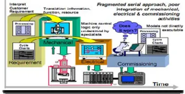
Current manufacturing automation systems are normally implemented in rigid hierarchical structures. The current approach, whilst well established and using well proven methods, still follows a classical rigid sequential model and uses an ad-hoc collection of poorly integrated tools and methods to take customer requirements and translate them into the desired system. As shown in the Figure-1, in the current approach the design, build and validation of automation systems takes place sequentially. In such an engineering process the validation of a system cannot be carried out until
[image:3.612.350.540.309.406.2]the final stage of the system’s development, when all electrical, mechanical units and the control software have been integrated. It is obvious that any unforeseen delays that occur during these activities will result in the delay of succeeding activities and hence delay the system delivery date. This adversely affects the lead time of a production machine and thus results in a failure to gain a competitive edge and market share (R.Harrison et al, 2001). Also, such an engineering approach heavily relies on the knowledge and experience of the engineering team. Moreover, the control codes developed for such systems are often monolithic and unstructured, making them difficult to understand, modify and reuse. Due to this, any alteration in the automation system is time consuming, complex, error prone and expensive. This results in an adverse impact on the commissioning and ramp-up time and can also lead to performance degradation.
Figure 1- Current Engineering Process of a Traditional Automation System (R.Harrison et al, 2006)
built based on autonomous mechatronic units (Martinez Lastra, J.L., 2002) ,Modular Machine Design Environment (MMDE) (Moore, P.R et al, 2003) proposed and implemented in VIR-ENG research project for designing, implementing and verifying control systems for agile modular manufacturing machinery, a modular autonomous material handling equipment solution for flexible automation described in (Bj et al, 2004), a fully automated robotic system in a modular way to meet the needs of a high throughput chemistry laboratory described by Manley (Manley, J.D et al, 2008) and a modular approach for production system engineering by adopting mechatronic objects proposed by researchers from Daimler AG and the University of Magdeburg (M. Bergert, J.K, 2010).
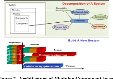
[image:4.612.102.285.547.676.2]The component-based approach (R.Harrison et al, 2006) proposed by researchers from Loughborough University aims at building reconfigurable modular automation systems for automotive power-train assembly systems. In this approach, a whole transport and assembly system can be decomposed ultimately into reusable and re-configurable components with embedded knowledge of control, 3D modelling, kinematics, and particular resources. A simplified representation of the structure of a component-based modular approach is shown in Figure-2 (upper part). Components can be designed, implemented, and validated concurrently and independently by various vendors. An automation system developed using this approach is inherently modular, reconfigurable and can be quickly developed in a time- and cost-effective manner through combining pre-validated components, as shown in Figure-2 (lower part). Evaluation work at ThyssenKrupp Krause showed that a saving of about 50% in overall build time of a control system on a reference assembly machine can be achieved by using a component-based approach (R.Harrison et al, 2001).
Figure 2- Architecture of Modular Component-based Approach
The authors are currently working on a research project named Business Driven Automation (BDA) applying the component-based concept through
collaborative research involving Loughborough University, Ford Motor Company and their machine builders and control vendors. This project aims to enable the realisation of next generation business-driven automation systems which can be readily evolvable under the direct control of the end-user and can be pre-defined in a modular form to enable the majority of process engineering to occur before the beginning of product engineering. Providing a virtual engineering environment for component-based assembly automation systems and a common engineering model that can effectively support the supply chain partners throughout the machine’s lifecycle is the main objective of this research. This virtual engineering environment is to facilitate the virtual construction, testing and validation of new production facilities prior to their physical build. Fundamentally, this engineering application is to 1) reuse the proven system commonalities from the previous projects, 2) provide efficient (re)configuration capabilities within the powertrain assembly systems and 3) provide robust launch of new production systems. The virtual engineering toolset enables the development of a practical and effective set of reusable machine components that could be easily deployed and integrated to build a desired automation system. The functionality and know-how for operation and error recovery are embedded into the components; making them intelligent in the context of having the ability to decide ‘what to do’ and ‘when to do’ a task.
Based on the requirements of the end-user (i.e. Ford) and their supply chain partners, the engineering toolset has been designed into a set of modules. These include a) a Core Component Editor, b) a virtual machine operator V-Man c) and a Runtime/Installation support. These modules are briefly described below.
a) The Core Component Editor provides 3D virtual modelling environment to develop and (re)configure manufacturing systems.
b) The purpose of the V-Man engineering module is to provide support for semi-automatic and manual assembly stations, integrating and optimising the interaction between machines and operators.
c) The Runtime/Installation module brings engineering concurrency between mechanical and controls engineering by automatically generating the control software, reusing information from 3D CAD models.
3. VIRTUAL COMMISSIONING
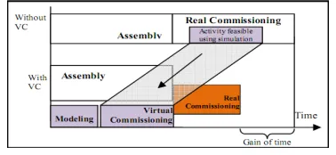
[image:5.612.99.288.421.508.2]The shrinking production cycle is making the production ramp-up time an important factor for a product’s economic success. The ramp-up phase starts with the complete assembly of a production system and ends with the achievement of the targeted quality at a specified cost and output rate (S.Lee et al, 2007). The ramp-up phase can be divided into the commissioning and run-up phases. Control system malfunction is a major source of the time delay in prolonging the ramp-up phase. Presently control software engineering is responsible for more than half of the malfunctions of highly automated production equipment and is typically carried out during the commissioning phase. An investigation for the German Association of Machine Tool Builders showed that the correction of defective control software consumes up to 60% of commissioning time and accounts for 15% of time-to-delivery (Reinhart, G. and G. Wünsch, 2007). This challenge can be relieved by virtual commissioning, in which a virtual prototype of the to-be system is used to validate control software on an actual Programmable Logic Controller (PLC) and Human-Machine Interface (HMI) before the physical integration of all the devices occurs on the shop-floor, thereby a saving of ramp-up time can be achieved, as shown in Figure-3.
Figure 3- Time Benefit of Virtual Commissioning (S.Lee et al, 2007)
Current approaches to build a virtual prototype for virtual commissioning can be classified into Full Simulation of Machinery (FSM) and Hardware-in-the-Loop (HIL) simulation. The FSM approach includes a simulation of the production equipment as well as the control hardware itself. This approach can be carried out within the control system hardware; however, the control software can only be tested on a pseudo-code basis. In a HIL simulation, on the other hand, the control software can be tested under more realistic conditions by connecting the virtual prototype of a machine to a real control hardware, thereby avoid making changes to the software afterwards. The HIL simulation approach has been applied by most researchers in the commissioning of different levels
of plant hierarchy (Reinhart, G. and G. Wünsch, 2007).
There are a large number of engineering tools for virtual commissioning in the market from a range of vendors. Typical examples of the state-of-the-art commercial solutions include Delmia Automation, UGS Tecnomatix, INVISION, WinMod and ControlBuild. Each of these tools has its own strengths and limitations and provides several good functionalities to conduct the virtual commissioning of a machine. However, from control point of view none of these tools fully support the required industrial functionalities, such as information reuse from simulated machine models to generate the required control logic. An industrial survey conducted by the authors within the automotive sector has shown that currently available tools only achieve about 10-20 percent of the control requirements of the user.
In order to provide a more complete solution, Loughborough University is conducting research which aims to enable the virtual engineering toolset (as discussed in the previous section) to fully support the virtual commissioning of automations systems. In this context, the tools are provided with User Interfaces (UI) and functions dedicated to the design of automation systems’ control layout as well as a lightweight 3D virtual environment. CAD models of machine elements can be imported and assembled to build a 3D virtual representation of components. Kinematics can then be applied to the moving parts of components by defining the type of motion (such as rotation or translation), direction and amplitude of the motion. The control behaviours of each component are defined using a state-transition diagram. Each state defines either static position of a component (e.g. home position) or a dynamic state (e.g. moving to work position). This allows viewing of an animation of a machine’s behaviour; thus enabling virtual testing, debugging and validation of system behaviour. This not only enables the virtual commissioning of a machine but also makes possible the realisation of the concept of a pre-validated and pre-commissioned library of machine components which can be quickly configured to develop new systems.
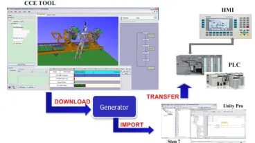
engineering toolset. This information is then processed and converted into executable PLC control code. This will enable machine builders to develop control applications at a higher level of abstraction by utilising the functionality of reusable components without worrying about their low-level programming details. The integration of this novel control method with BDA virtual engineering tools will allow testing of the virtual models of machines against their generated control code and the HMI screens using the physical control hardware (such as PLCs) in the loop. This will also enable the end-user to train their technical staff before the physical machines arrive at their shop floor. The virtual engineering tool and the concept of its integration with control systems are illustrated in Figure-4.
Unlike other commercially available virtual engineering solutions, the CCE tool aims to rely on generic, open data formats for both control and modelling data. This has the potential to increase its integration capabilities with other engineering tools. However, the CCE toolset does not currently adopt a standard neutral data format.
From the review of relevant available engineering tools it becomes visible no single tool available in the market can fulfil all the requirements of automation system engineering. To perform the complete process of virtual commissioning, normally several different engineering tools need to be used in combination. If the involved tools are from the same IT vendor, a seamless data exchange between the IT systems based on the vendor-specific proprietary data interfaces is normally available; however, if these tools are from different vendors, there is no possibility to exchange cross-functional data models between two tools without a loss of information due to the lack of common data model for data exchange (Manley, J.D et al, 2008). To achieve a successful industrial introduction of virtual commissioning, some typical issues summarized below still need to be addressed:
•Insufficient data exchange between engineering tools from different vendors: A virtual prototype of the to-be system is the precondition of virtual commissioning. Building this virtual model needs to combine data from different disciplines, like mechanical, electrical, control logic etc, which normally come from different engineering tools. Data exchange between virtual commissioning tools and these discipline-specific tools is still a challenge due to the proprietary data formats. Currently, some of these data are exchanged in paper-based ways, which is mostly manual, repetitive, error-prone and time-consuming.
•Lack of common data model to represent modular automation systems validated via VC:
Reusing existing models to build a new system is a key principle of a modular approach. The virtual models validated by virtual commissioning, like topology information and control logic information, should be stored in common data models based on neutral data formats so that they can be subsequently reused by different tools. However, this is not the case at the present due to the different data structures and data formats of different VC tools.
•No complete solution for direct deployment of control logic data from virtual systems to real systems: The PLC program should be generated automatically based on the control logic information which is already defined during virtual construction and then validated by virtual commissioning. However, there is lack of tools which can directly translate this control information into full usable control code.
[image:6.612.352.536.491.594.2]The above challenges have been difficult to address in the past due to a lack of a suitable open standard data format. A tool-neutral cross-functional data exchange format named AutomationML for data exchange in automation system engineering is being developed by AutomationML organization. AutomatioinML has been developed to enable the efficient data exchange between different discipline-specific automation engineering tools. In this paper we are investigating its use to support the data representation of a modular automation system, thus enabling more open data exchange. The following section provides a brief description of AutomationML and its potential to address the above challenges.
Figure 4- Virtual Engineering Environment Developed in BDA Project
4. AUTOMATIONML – A NEUTRAL DATA EXCHANGE FORMAT FOR
AUTOMATION ENGINEERING
2008. The goal of AutomationML is to provide a tool-independent format for data representation and data exchange between different software tools involved in automation system engineering without loss of information.
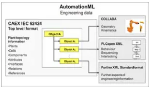
AutomationML aims to be a neutral data format which is usable in the whole process of automation systems engineering. Its data representation capabilities are still being expanded by the AutomationML organisation, for instance, a new work group was initiated in February 2011 focusing on network models, device description and wiring plans. In its current version, AutomationML covers information on plant topology, geometry, kinematic, and logic (sequencing, behaviour and interlocking). This information is essential to build virtual prototypes for virtual commissioning and for the deployment of the resultant machines. If the tools utilised during virtual prototyping and machine deployment are from different vendors, data exchange between them is difficult due to the large number of required interfaces. Data exchange can be potentially realised with significantly reduced number of interfaces by using AutomationML.
[image:7.612.336.538.356.461.2]After virtual commissioning, validated virtual models at different levels, e.g., system and component, behaviour models will be available for further application and reuse if these information can be saved in a proper neutral data format. As illustrated in Figure-5, AutomationML adopts an object-oriented paradigm and allows modelling of real plant components as data objects encapsulating information of different disciplines as their properties which typically include data of geometry, kinematic, behaviour, position within the hierarchical plant topology and the relations to other objects. An object can consist of other sub-objects and can itself be a part of a larger composition or aggregation. Moreover, AutomationML employs existing industry data formats for the storage of different aspects of engineering information, as shown in Figure-5: COLLADA is used for storage of geometric and kinematic information, PLCOpen XML serves for the storage of sequences and behaviours, and CAEX is used as the top level format that connects the different data formats to comprise the plant topology.
Figure 5- Architecture of AutomationML (Drath. R, 2008)
5. DATA EXCHANGE IN VC VIA AUTOMATIONML
A framework for virtual prototype construction and virtual commissioning as illustrated in Figure-6 has been proposed and is being developed in Loughborough University to enhance the openness of CCE tool. This framework adopts AutomationML as a neutral data format for the data exchange and data representation. To implement the transformation of discipline-specific data, a plug-in based framework called Conditioner Pipeline Framework (CPF) needs to be implemented. The simplified structure of the CPF is shown in Figure-7. By using the CPF, the transformation can be performed in the following three steps:
1. Load data from input data format by loader module.
2. Transform information in conditioner to the targeted data format, or optionally to an intermediate data format, like IML for the logic data.
[image:7.612.116.271.630.720.2]3. Save the transformed as target data format, like CAEX, COLLADA and PLCopen XML.
Figure 6- Virtual commissioning framework based on AutomationML
Figure 7- Simplified structure of CPF
To implement the transformation of plant topology information, a library called AutomationML Engine provided by AutomationML organisation will be used to handle CAEX files. This process is more complex as there is a great deal of user-defined information in topology data. The key issues required to be addressed in implementing data format transformation are summarised as follows:
1.Extract tool-specific data from different files. In CCE Tool, hierarchy information is saved in XML files while most of the logic information is stored in database.
2.Map different terminologies which are used in different tools to describe the same object, e.g. position information of an object is named “link point” in CCE tool while its equivalent word in AutomationML is “frame”.
[image:8.612.101.261.547.642.2]Build class libraries including role class library, interface class library and system unit class library, especially system unit class library, which are missing from CCE Tool data representation. Predefined AutomationML object types - classes are essential to AutomationML data format because it follows an object-oriented paradigm. Compared with role class library and interface class library, which are AutomationML standard library, system unit class library needs to be defined by users. A comparison between the data structure of CCE Tool and that of AutomationML are illustrated in Figure-8.
Figure 8 -Data structures of AutomationML and CCE Tool
By employing this framework, the following advantages can be gained:
Efficient data exchange to build virtual prototypes: If each relevant engineering tool involved in the automation system engineering
stores its data in an open standard neutral data format or provides interfaces to import/export this standard data format, efficient data exchange between these tools and virtual commissioning can be efficiently achieved even if the required tools are from different vendors, thereby some duplicate works can be avoided.
A tool-independent data representation for validated virtual models: Validated virtual models saved in a tool-independent data format will be reusable even if VC tools are upgraded or even changed. This will enable a seamless re-usability of those models and a protection of past engineering investments and expertise.
A common control behaviour model: It is the foundation for automatic generation of PLC program. After virtual commissioning, all the validated control behaviour data could be saved as SFC models. This has the potential to significantly reduce the effort to implement direct deployment of control logic into real machines.
In the following section, a case study is provided to show how to transform the data model of a modular automation system in the CCE engineering tool into an equivalent model based on the AutomationML data format.
6. CASE STUDY
This section presents a case study of building an open data model for a Festo test rig based modular automation system, which has been validated in the CCE tool, as shown in Figure-9. The current data structure and the equivalent data structure based on AutomationML for the Festo Rig are described respectively.
Figure 9 - Real Festo rig (left) and its virtual prototype in CCE (right)
In the CCE tool, all the components are categorised into actuators, sensors and non-controls. An actuator contains the information of geometry, kinematic and logic. A sensor contains information of geometry and state while a non-control only has geometry information. Geometry information of a component in the CCE tool is stored in a file of VRML data format. The logic information of a component is described as a state transition diagram.
except its geometry, can be exported as an xml file for further analysis or reuse. The simplified structure of the xml file including the information about a section of the Festo rig is shown in Figure- 10. The information included in this file is difficult to reuse in other tools because it does not follow an open standard, although it is an xml-based file. Also, the fact that all the information is stored in the same file makes it difficult to extract discipline-specific information for further application, e.g. using logic information to generate PLC code,
<System>
…
</System>
<Component Pusher>
<Geo>pusher.wrl</Geo>
<STD>
</Component Pusher> </STD>
<State>
</State> </Transition> <Transition>
…
<Condition> </Condition>
Pusher.wrl(VRML File)
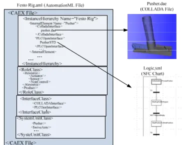
[image:9.612.361.544.53.198.2]Festo Rig.xml
Figure 10 - Data structure of a system (Festo rig) in the CCE Tool
In this context, a new data model based on AutomationML has been developed for representing such a modular automation system. The current data models of CCE Tool can be transformed into the AutomatioinML-based data models using the CPF which has been introduced in previous section. In this new data model, the hierarchical information, the geometry & kinematic information and the logic information of the Festo rig are stored in different xml-based files of their corresponding data formats which are CAEX, COLLADA and PLCOpen xml (described by Sequential Function Chart) respectively. In the CAEX file, three classes, which are Role Class, Interface Class and System Unit Class, are defined first. According to the information contained in Festo Rig, three roles (resource, product and process), two interfaces (COLLADAInterface and PLCOpenInterface) and 14 system units (work part, floor, sensor, pusher, swivearm, conveyor, rotate table, et al) are defined. Role class Resource still includes three sub-role classes which are Actuator, Sensor and Non-control. All the system unit classes inherit from the corresponding role classes, e.g. Pusher inherits from Actuator, Floor inherits from Non-control and Work Part inherits from Product. The hierarchy data structure (CAEX) includes COLLADAInterface and PLCOpenInterface linking to geometry data and control logic data. The simplified data structure of Festo Rig based on AutomationML is shown in Figure-11.
Figure 11 - Data structure of the Festo rig based on the AutomationML format
As more and more engineering tools become AutomationML compliants, this new data model can be directly reused by other engineering tools for the virtual commissioning of automation systems. Furthermore, discipline-specific information can now be readily extracted and used in further engineering tools, e.g. a PLC code generator to automatically generate PLC code using the logic information which has been validated in CCE tool and saved in the Sequential Function Chart format.
7. SUMMARY AND OUTLOOK
Reconfigurable Manufacturing Systems and Virtual Commissioning have been regarded as two key enablers to achieve agile manufacturing in response to the need for mass-customisation. The research work carried out in MSI Research Institute at Loughborough University provides an innovative virtual engineering approach and a corresponding application tool to the implementation of modular automation systems. The main advantages of this approach are: 1) the modelled components can be reused and reconfigured to achieve various machine configurations, 2) virtual machine prototypes will be highly portable as the data has been saved in a generic, open data format, and 3) the control logic information included in the validated machine models can be deployed directly to corresponding real machine thereby avoiding time-consuming and error-prone manual work.
[image:9.612.85.302.192.335.2]representation and object-oriented architecture. A collaborative framework based on AutomationML is being developed at Loughborough University. This framework offers the potential to achieve efficient data exchange between the CCE virtual commissioning tools and other relevant engineering tools and applications. A data model based on AutomationML for describing CCE-based modular automation systems has been defined. These application system models have been validated via virtual commissioning using the CCE tools. The neutral format-based data model created enables the validated information to be efficiently reused by relevant engineering tools from different vendors.
Finally, it should be noted that to implement complete seamless virtual engineering, a range of other issues still remain to be addressed. These include:
•More information from different disciplines, like I/O mapping, hydraulic and pneumatic etc, needs to be included in virtual models to realise a complete virtual commissioning. The AutomationML development organisation is trying to include these kinds of information in AutomationML.
•The virtual prototyping capability needs to be extended to support direct deployment of control software. This remains problematic for multiple PLCs due to the wide variety of PLCs brands which dominate the market, each with their own vendor-specific software.
8. ACKNOWLEDGEMENT
The authors gratefully acknowledge the support of the EPSRC and our industrial collaborators through the IMCRC Business Driven Automation (BDA) project in carrying out this research.
REFERENCES
Bj, et al., Using autonomous modular material handling equipment for manufacturing flexibility, in Proceedings of the 36th conference on Winter simulation. 2004, Winter Simulation Conference: Washington, D.C.
Drath, R., et al. AutomationML - the glue for seamless automation engineering. in Emerging Technologies and Factory Automation, 2008. ETFA 2008. IEEE International Conference on. 2008.
ElMaraghy, H.A., M.A. Ismail, and H.A. ElMaraghy, Component Oriented Design of Change-Ready MPC
Systems, in Changeable and Reconfigurable
Manufacturing Systems. 2009, Springer London. p.
213-226.
Harrison, R., et al., Reconfigurable modular automation systems for automotive power-train manufacture.
International Journal of Flexible Manufacturing Systems, 2006. 18(3): p. 175-190.
Harrison, R., et al., Distributed engineering of
manufacturing machines. Proceedings of the
Institution of Mechanical Engineers, Part B: Journal of Engineering Manufacture, 2001. 215(2): p. 217-231.
Jens Kiefer, T.B., Helmut Bley and Mechatronic-oriented Engineering of Manufacturing Systems Taking the Example of the Body Shop, in Conference on Life Cycle Engineering. 2006: Leuven.
Lee, S., et al., A component-based approach to the design and implementation of assembly automation system.
Proceedings of the Institution of Mechanical Engineers, Part B: Journal of Engineering Manufacture, 2007. 221(5): p. 763-773.
M. Bergert, J.K., Mechatronic Data Models in Production Engineering in 10th IFAC Workshop on Intelligent Manufacturing Systems. 2010: Lisbon, Portugal.
Manley, J.D., et al., Modular Approaches to Automation System Design Using Industrial Robots. Journal of the Association for Laboratory Automation, 2008. 13(1): p. 13-23.
Martinez Lastra, J.L. Reference Mechatronic Architecture for Actor-based Assembly System . 2004, Tampere: Tampere University of Technology
Mehrabi, M.G., A.G. Ulsoy, and Y. Koren, Reconfigurable manufacturing systems: Key to future manufacturing.Journal of Intelligent Manufacturing,
2000. 11(4): p. 403-419.
Michalos, G., et al., Automotive assembly technologies review: challenges and outlook for a flexible and adaptive approach. CIRP Journal of Manufacturing Science and Technology. 2(2): p. 81-91.
Moore, P.R., et al., Virtual engineering: an integrated approach to agile manufacturing machinery design and control. Mechatronics, 2003. 13(10): p. 1105-1121. Reinhart, G. and G. Wünsch, Economic application of