University of Warwick institutional repository: http://go.warwick.ac.uk/wrap
A Thesis Submitted for the Degree of PhD at the University of Warwick
http://go.warwick.ac.uk/wrap/3130
This thesis is made available online and is protected by original copyright. Please scroll down to view the document itself.
Mimicking the Human Olfactory
System: A Portable e-‐Mucosa
by
Fauzan Khairi Che Harun School of Engineering University of Warwick
A thesis submitted to the University of Warwick for the degree of Doctor of Philosophy
i
Contents
Heading
Page
Contents i
List of Figure v
List of Tables viii
Summary ix
Acknowledgements x
Declaration xi
Selected Abbreviations and Acronyms xii
CHAPTER 1 ... 1
1.1 INTRODUCTION... 1
1.2 MAMMALIAN OLFACTORY SYSTEM... 1
1.1 ELECTRONIC NOSES... 3
1.2.1 Sensor-‐based gas detectors ... 5
1.2.2 Instrument-‐based gas detectors ... 8
1.3 COMMERCIAL ELECTRONIC NOSE... 11
1.4 APPLICATIONS OF ELECTRONIC NOSES... 12
1.5 OUTLINE OF THESIS... 15
1.6 REFERENCES... 16
CHAPTER 2 ... 19
2.1 INTRODUCTION... 19
2.2 MIMICKING THE BIOLOGICAL OLFACTORY SYSTEM... 20
2.3 SYSTEM MODULE... 23
2.3.1 Micro gas sensor array ... 24
2.3.2 Carbon Black Polymer Sensor Review ... 25
2.3.3 Gas Chromatography Overview... 29
2.3.4 Microfabrication Overview ... 31
2.4 SPATIO-‐TEMPORAL INFORMATION... 32
2.5 CONCLUSION... 34
2.6 REFERENCES... 35
CHAPTER 3 ... 38
3.1 INTRODUCTION... 38
3.2 SENSOR ARRAY DESIGN... 38
3.2.1 Design of chemoresistive sensor substrate ... 39
3.2.2 Multiplexed Array Pad Design... 44
ii
3.3.1 Gold Resistive temperature sensor ... 46
3.4 SENSOR FABRICATION... 48
3.5 CARBON BLACK-‐ POLYMER DEPOSITION... 54
3.5.1 Material ... 55
3.5.2 Solution Preparation and Deposition ... 56
3.6 DEPOSITION PROCESS... 59
3.7 SENSOR CHARACTERIZATION... 59
3.8 PORTABLE E-‐MUCOSA DESIGN CONSIDERATION... 64
3.9 CONCLUSIONS... 64
3.10 REFERENCES... 65
CHAPTER 4 ... 67
4.1 INTRODUCTION... 67
4.2 MICROSTEREOLITHOGRAPHY FABRICATION... 68
4.3 MICROFLUIDICS DESIGN EVOLUTION... 72
4.3.1 Preliminary Design -‐ Box Type... 73
4.3.2 Spiral Design ... 76
4.4 POST FABRICATION... 79
4.4.1 Sealing ... 79
4.4.2 Stationary Phase Coating... 81
4.5 DESIGN OF OTHER COMPONENTS... 87
4.5.1 Sensor Chamber ... 87
4.5.2 Odour Distribution Chamber... 89
4.5.3 Deposition Mask ... 90
4.6 PORTABLE DEVICE ADAPTATION... 91
4.7 CONCLUSIONS... 93
4.8 REFERENCES... 94
CHAPTER 5 ... 96
5.1 INTRODUCTION... 96
5.2 ELECTRONIC MUCOSA-‐NOSE INSTRUMENT... 96
5.3 LARGE SENSOR ARRAY ELECTRONICS CIRCUITRY... 99
5.3.1 Data Acquisition, Constant Current and Signal Conditioning -‐ Board 1 ... 100
5.3.2 Sensor Array Multiplexer and Odour Delivery -‐ Board 2 ... 102
5.4 ODOUR DELIVERY SYSTEM... 105
5.5 DATA ACQUISITION SOFTWARE... 106
5.6 SUPPORT SOFTWARE... 110
5.6.1 Live Deposition Viewer... 110
5.6.2 Vapour Concentration Calculator ... 111
5.6.3 NOSE II XML Converter... 112
5.7 DATA PROCCESSING SOFTWARE... 114
5.8 CONCLUSIONS... 115
5.9 REFERENCES... 116
CHAPTER 6 ... 117
6.1 INTRODUCTION... 117
6.2 DESIGN AND SPECIFICATION... 119
iii
6.3 SYSTEM MODULES... 121
6.3.1 Large Sensor Array... 121
6.3.2 Retentive Column... 123
6.3.3 Preconcentrator ... 123
6.4 PEM ELECTRONICS... 124
6.4.1 Main Control System : Board A ... 125
6.4.2 Data Acquisition System – Board B... 127
6.5 ODOUR DELIVERY SYSTEM... 129
6.6 CASING DESIGN AND FABRICATION... 132
6.7 SOFTWARE DEVELOPMENT... 133
6.7.1 Board A Firmware ... 134
6.7.2 Board B Firmware ... 135
6.8 DATA VIEWER AND XML CONVERTER... 136
6.9 CONCLUSIONS... 137
6.10 REFERENCES... 139
CHAPTER 7 ... 140
7.1 INTRODUCTION... 140
7.2 LARGE SENSOR ARRAY CHARACTERISATION... 141
7.2.1 Stability test ... 141
7.2.2 Large Sensor Array Representation ... 142
7.2.3 Wide Sensor Diversity and Redundant Sensor Tunings ... 143
7.2.4 Temperature effects... 145
7.2.5 Flow velocity effects... 146
7.2.6 Large sensor array Classification ... 147
7.3 MICRO RETENTIVE COLUMN CHARACTERISATION... 150
7.3.1 Temporal Information... 150
7.3.2 Comparison between uncoated and coated microchannel... 152
7.3.3 Effect of various dimension micro retentive column... 154
7.3.4 Effect of Flow Rates ... 156
7.4 ONE DIMENSIONAL COLUMN PERFORMANCE... 157
7.5 DUAL DIMENSIONAL COLUMN PERFORMANCE... 161
7.6 SIMPLE SPATIO-‐TEMPORAL CLASSIFICATION... 164
7.7 PORTABLE E-‐MUCOSA SYSTEM OPTIMIZATION... 166
7.8 ADVANCED SPATIO-‐TEMPORAL ODOUR CLASSIFICATION... 168
7.9 CONCLUSIONS... 172
7.10 REFERENCES... 172
CHAPTER 8 ... 173
8.1 OVERVIEW... 173
8.2 PROJECT OBJECTIVES... 174
8.3 DEVELOPMENT OF AN ARTIFICIAL BIO INSPIRED OLFACTORY SYSTEMS... 175
8.4 PORTABLE E-‐MUCOSA... 175
8.5 CHARACTERISATION AND PERFORMANCE OF THE E-‐MUCOSA SYSTEM... 178
8.6 FURTHER WORKS... 178
iv Appendix A : Sample XML e-‐Nose File
Appendix B : Firmware Flow Chart
Appendix C : Portable e-‐Mucosa Schematics
v
List of Figures
Heading
Page
Figure 1.1: Anatomy of a Human Olfactory System 2
Figure 1.2: (a) Electronic Nose versus (b) Human Olfactory System 4 Figure 1.3: Sensor Technology. a) Osmetech 48 Conducting Polymer sensors b) Figaro TGS
822 Tin Oxide sensors c) miths Detection (previousy known as Cyrano Sciences) 32-‐sensor integrated array d) Polymer based chemoresistive sensor from
Osmetech e) NASA 32 integrated sensor array 7
Figure 2.1: General structure of a chemical resistive gas sensor 24
Figure 2.2: Concept of Spatio-‐Temporal Signal Generation 33
Figure 3.1: Basic response of a chemo resistive sensor 39
Figure 3.2: Basic Structure of single gas sensor 41
Figure 3.3: Dimension of individual sensor 41
Figure 3.4: Alignment mask for large sensor array 43
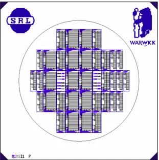
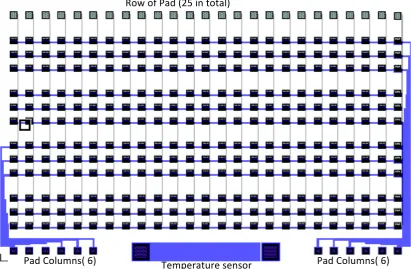
Figure 3.5: Final wafer design with several sensor array sizes 44 Figure 3.6: Array of 300 sensors in 25 x 12 configuration 45
Figure 3.7: Gold resistivity vs Temperature 47
Figure 3.8: Gold temperature sensor design layout 47
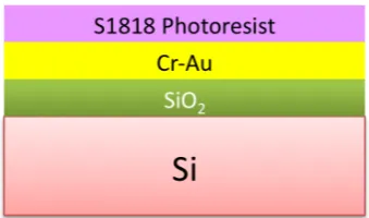
Figure 3.9: Silicon Oxide coated with Au and Cr layer with photoresist 49
Figure 3.10: UV Light exposed through Mask 1 49
Figure 3.11: Etching process removing Metal1 50
Figure 3.12: Coating substrate with insulator layer 50
Figure 3.13: UV exposure using Mask 2 for insulator layer 51
Figure 3.14: Metal2 fabrication with Mask 3 52
Figure 3.15: Passivation layer UV exposure 52
Figure 3.16: a) Wafer with Metal 1 b) Wafer with Metal 1 and 2 layer 53 Figure 3.17: Carbon Black Composite deposited onto metal electrode 54 Figure 3.18: a) MSL Mask b) Mask aligned to sensor c) Mask Alignner machine 57 Figure 3.19: Sensor numbering and polymer deposition location 58 Figure 3.20: Seven sensor responses to simple analyte, a) ethyl acetate b) toluene c)
ethanol 60
Figure 3.21: Color map for 300 sensor response to essential oils 61 Figure 3.22: Sensor response to different concentration of a) toluene and b) ethanol 62 Figure 3.23: Sensor response taken at seven different flow rates 63 Figure 3.24: a) Sensor array on Portable e-‐Mucosa sensor package b) Sensor package
plugged onto mask aligner adapter 64
Figure 4.1: Envisiontec Perfactory Mini 70
Figure 4.2: Envisiontec Perfactory Mini Functional Diagram 71
Figure 4.3: Fabrication Process for MSL 3D Structure 72
Figure 4.4: a) Boxed Type Micro Retentive Column b) Preliminary Chamber design 73 Figure 4.5: a) CAD design of Hybrid Column-‐Chamber b) Hybrid Column-‐Chamber (with 5
pence piece for scale) 74
Figure 4.6: Sharp edge created when the column is sealed with glass 75
Figure 4.7: Spiral based Micro Retentive Column 76
vi Figure 4.9: Semi rounded column sealed with glass 77
Figure 4.10: Blockage created by excess adhesive 79
Figure 4.11: a) Microchannel sealed with UV adhesive b) Micro column filled with water 80 Figure 4.12: Dynamic coating example of open tubular capillary column 82 Figure 4.13: tatic coating of open tubular capillary column 83 Figure 4.14: SCS PDS 2010 Parylene-‐C vapour deposition system 85 Figure 4.15: a) Initial design of sensor chamber b) Patch of glue blocking chamber sealing
properly 88
Figure 4.16: a) Miniaturised sensor chamber design b) alignment hole cover c) Exploded
view of chamber assembly 89
Figure 4.17: Odour distribution chamber 90
Figure 4.18: a) Deposition mask with dimensions b) Deposition mask aligned under
microscope 90
Figure 4.19: a) Modified sensor chamber b) Preliminary sensor connector c) Current sensor
connector 91
Figure 4.20: Mask for Portable e-‐Mucosa sensor deposition 92
Figure 4.21: a) CAD Design of Temperature/Humidity Sensor chamber b) CAD Design of preconcentrator chamber c) Connection Converter & column bridge d)
Assembled Column for Portable e-‐Mucosa 93
Figure 5.1: Diagram of Electronic Mucosa Dual Dimensional concept 97 Figure 5.2: Block diagram of component on each board and interfacing with PC 100
Figure 5.3: Functional Diagram of Data Acquisition System 101
Figure 5.4: Board 1-‐ Data Acquisition and Signal Conditioning Board 102 Figure 5.5: Board 2-‐ Senor array multiplexer and Odour Delivery control 103 Figure 5.6: Integration- Odour delivery system and Data Acquisition Electronics
Diagram 105
Figure 5.7: Cooling Bath for test analytes 106
Figure 5.8: Test panel for Data Acquisition Board 1 107
Figure 5.9: Vapour Delivery system developed at University of Warwick 108 Figure 5.10: Vapour Test panel for 1200 sensor in 4 sensor arrays 108
Figure 5.11: Sensor response viewer 109
Figure 5.12: Live Sensor Deposition MonitorFigure 5.11: Live Sensor Deposition
Monitor 110
Figure 5.13: Interface cable from mask aligner to data acquisition board 111 Figure 5.14: Main panel of Vapour Concentration Calculator with Functional Block Diagram
111
Figure 5.15: E-‐nose XML data structure 112
Figure 5.16: XML Converter for 1200 sensors 113
Figure 5.17: Multisens Analyzer displaying 300 sensors response to Toluene and Ethanol
114
Figure 6.1: Portable e-‐Mucosa concept diagram with built in preconcentrator 119
Figure 6.2: Block Diagram of complete portable e-‐Mucosa 120
Figure 6.3: Coating Arrangement based on Table 3.2 121
Figure 6.4: a) Bottom view of the peM with three 200 sensors array b) Retentive column
with connection adapter 122
vii
Figure 6.7: View of Font and back of Board A 125
Figure 6.8: View of Front and Back of Board B 127
Figure 6.9: Block diagram of odour flow in the system 129
Figure 6.10: a) Three layer PCB of Portable e-‐Mucosa b) CAD Design of PeM casing c) Casing
for PeM created with deposition 132
Figure 6.11: Sample Menu Item in the Portable e-‐Mucosa 135
Figure 6.12: Response Viewer and Format Converter 137
Figure 6.13: Comparion shot between PeM and Cyranose 320 139
Figure 7.1: Drift and Noise for sensor expose to laboratory air 141
Figure 7.2: Large Sensor Array Representation 142
Figure 7.3: Sensor Response to Ethanol and Toluene with 9 polymer coating shown 143 Figure 7.4: Group of redundant sensor with uncoated and faulty sensor 145 Figure 7.5: Sensor response to ethanol at different temperature 145 Figure 7.6: a) Response Magnitude vs Flow Rates b) Response Time vs Flow Rates 146 Figure 7.7: Simple PCA with three simple odour with sensor response 148
Figure 7.8: Simple PCA of Four Essential oil data 149
Figure 7.9: Temporal Information determination 150
Figure 7.10: Temporal information for dual dimensional column setup 151 Figure 7.11: a) Response after uncoated channel b) Reponse after carbowax coated
channel 153
Figure 7.12: Sensor response with three different size column 155
Figure 7.13: Effect of coumn length 155
Figure 7.14: Sensor responses to ethyl acetate at different flow rate with OV1 column 157 Figure 7.15: One dimensioanl setup for generating spatio temporal response 157 Figure 7.16: Ethyl acetate and Ethanol responses in one dimensional setup 158 Figure 7.17: Partition Coefficient for three different chemicals with two stationary phase
159
Figure 7.18: Sensor response towards ethanol and ethyl acetate before and after retentive
column 160
Figure 7.19: Dual Dimensioanal e-‐Mucosa setup 161
Figure 7.20: Temporal information with dual dimensional setup 163 Figure 7.21: PCA Plot for three chemical using a) Spatial information only b) Temporal
information only c) Combined Spatio-‐Temporal information Spatial Temporal
Information 165
Figure 7.22: Sensor response with preconcentrator to ethyl acetate 166 Figure 7.23: Sensor 225 response to ethyl acetate with and without preconcentrator 167 Figure 7.24: Spatial information representation of three sensor array with four essential oil
170
Figure 7.25: Convolution results of four essential oil 171
Figure 8.1: Neuromorphic Olfactory chip responding to e-‐nose sensor response 181
viii
List of Tables
Heading
Page
Table 1.1: Various Sensor Types with advantages and disadvantages 8
Table 1.2: Commercial E-‐Noses 11
Table 2.1: Bio-‐Inspired Engineering with Nature Counterpart 21
Table 3.1: Pad Dimensions (unit : μm) 42
Table 3.2: List of Polymer Composite Composition with Solvent 56
Table 4.1: Dimension of spiral columns 78
Table 5.1: Component function in odour delivery system 104
Table 6.1: Vlaves and heater condition at certain period 131
Table 7.1: Accuraty matrix for PNN classifier utilizing an optiman sensor subset 171 Table 8.1: List of Components with comparable function to biological olfactory system 178
ix
Summary
The study of electronic noses has been an active area of research for over 25 years. Commercial instruments have been successfully deployed within niche application areas, for example, the food, beverage and pharmaceutical industries. However, these instruments are still inferior to their human counterparts and have not achieved mainstream success. Humans can distinguish and identify many thousands of different aromas, even at very low concentration levels, with relative ease. The human olfactory system is extremely sophisticated, which allows it to out-‐perform artificial instruments. Though limited, artificial instruments can provide a lower cost option to specific problems and can be an alternative to the use of organoleptic panels.
Most existing commercial electronic nose (e-‐nose) instruments are expensive, bulky, desktop units, requiring a PC to operate. In addition, these instruments usually require a trained operator to gather and analyse the data. Motivated to improve the performance, size and cost of e-‐nose instruments, this research aims to extract biological principles from the mammalian olfactory system to aid the implementation of a portable e-‐nose instrument. This study has focused on several features of the biological system that may provide the key to its superior performance. Specifically, the large number of different olfactory receptors and the diversity of these receptors; the nasal chromatograph effect; stereo olfaction; sniff rate and odour conditioning. Based on these features, a novel, portable, cost effective instrument, called the Portable e-‐Mucosa (PeM), has been designed, implemented and tested. The main components of the PeM are three sensor arrays each containing 200 carbon black composite chemoresistive sensors (totalling 600 sensors with 24 different tunings) mimicking the large number of olfactory receptors and two gas chromatographic columns (coated with non-‐polar and polar compounds to maximise the discrimination) emulating the “nasal chromatograph” effect of the human mucus. A preconcentrator based on thermal desorption is also included as an odour collection system to further improve the instrument. The PeM provides USB and Multimedia Memory Card support for easy communication with a PC. The instrument weighs 700g and, with dimensions of 110 x 210 x 110 mm, is slightly larger than the commercial Cyranose 320 (produced by Smiths Detection).
x
Acknowledgements
Firstly, I thank Allah (S.W.T) for making all this possible. I would also like to express my upmost gratitude to my academic supervisor, Dr James Covington and Prof. Julian Gardner for giving me the opportunity of studying in this field, and for their constant guidance and support during my PhD. I would also like to acknowledge Universiti Teknologi Malaysia for their financial support during the three years of study. Also to all UTM staff, including Kak Ani and Kak Surati who have helped me a lot during my study. For practical work associated with my PhD, I would particularly like to thank the members of the Sensors Research Laboratory, School of Engineering, University of Warwick, including, Mr F. T. Courtney for his assistance in all mechanical matters and to Mr I. Griffiths for his helped is circuit layout and design. This works would not have been possible without both of you.
I am also thankful to all of my friends and colleagues, including T. Iwaki, J. Khawaja, P.H. King, J. Taylor, M.Talib, Mohd Azhar Abd Razak, Raja Kamaruzaman and S. Pathak for their constant support and encouragement during the course of this study. I would also like to acknowledge my wife, Siti Rohana Abd Rahman and kids for their constant support during my PhD.
Last but not least, I would like to acknowledge everyone who has helped me in one way or another, without which this would not have been possible.
xi
Declaration
The work described in this thesis is entirely original and my own, except where otherwise indicated.
Parts of this work have been presented at international conferences and published in the scientific literature listed below:
Journal Paper
1. F.K.Che Harun, J.E.Taylor, J.A.Covington, J.W.Gardner, “,An electronic nose employing dual-‐channel odour separation columns with large chemosensor arrays for advanced odour discrimination”, Sensor and Actuator B: Chemical, 2009, Volume 141, Issue 1, 134-‐140.
Conference papers
1. F.K.Che Harun, P.H. King, J.A. Covington, J.W. Gardner, “Novel Gas Chromatographic Microsystem With Very Large Sensor Arrays For Advanced Odour Discrimination”, IEEE Sensors 2007. Presented on October 28 -‐ 31, 2007 in Atlanta, USA.
2. F.K.Che Harun, J.Taylor, J.A. Covington, J.W. Gardner,”Dual-‐Channel odour separation columns with large chemosensor arrays for advanced odour discrimination”, IMCS 12, 2007. Presented on July 13-‐16 2008 in Ohio, USA. 3. James Taylor, F.K Che Harun, J.A. Covington, J.W. Gardner, “Applying
Convolution-‐Based Processing Methods to a Dual-‐Channel, Large Array Artifical Olfactory Mucosa”, ISOEN 13, 2009. Presented on 15-‐17 April 2009 at Brescia, Italy.
4. F.K.Che Harun, J.A. Covington, J.W. Gardner, “Portable e-‐Mucosa System: Mimicking the biological olfactory system”, Eurosensor XXIII, 2009.
xii
Selected Abbreviations and Acronyms
TERM DEFINITION
ADC Analogue to Digital Conversion
aVLSI Analogue Very Large Scale Integration CAD Computer Aided Design
CMOS Complementary Metal Oxide Semiconductor Carbowax 20M Poly( ethylene glycol)
DAC Digital to Analogue Conversion DMD Digital Micromirror Device e-mucosa Electronic Mucosa
E-nose Electronic Nose FET Field Effect Transistor FID Flame Ionisation Detector
GC Gas Chromatography
I/O Input/Output
LCD Liquid Crystal Display
LIGA Lithography Galvonoforming Abforming LSER Linear Solvation Energy Relationship MEMS Micro-Electro-Mechanical-System MOS Metal Oxide Semiconductor
MS Mass Spectrometry
MSL Microstereolithography
OB Olfactory Bulb
OS Operating System
OR Olfactory Receptor
PBA Poly (bisphenol A carbonate) PCA Principal Component Analysis PCB Printed Circuit Board
PCL Poly (caprolactone) PCX Poly (chloro P xylylene) PDE Partial Differential Equation PDMS Poly (dimethylsiloxane) PEG Poly (ethylene glycol)
PEVA Poly (ethylene-co-vinyl acetate) PMMA Poly (methyl methacrylate) PSB Poly (stylene-co-butadiene)
PSF Poly (sulfane)
PVC Poly (9-vinylcarbazole) PVPD Poly (vinyl pyrrolidone) PVPH Poly (4-vinyl phenol)
QCM Quartz Crystal Microbalance SAW Surface Acoustic Wave
Si Silicon
SiO2 Silicon Dioxide
SL Stereolithography
STL Stereolithography
SPI Serial Peripheral Interface
UV Ultra-Violet
VI Virtual Instrument
VLSI Very Large Scale Integration SE-30 Poly (dimethylsiloxane)
1
CHAPTER 1
1.1
Introduction
This chapter introduces the human olfactory system and compares it to current
electronic nose instruments, discussing both the strengths and weaknesses of both.
Next, current technology, devices and applications are discussed. The aims and
objectives of the research undertaken are then described. Lastly, an outline of the
thesis is presented.
1.2
Mammalian olfactory system
The sense of smell is always seen as a minor sense among the five major human
senses (sight, touch, taste, hearing and smell). Evolution created the sense of smell
as warning mechanism, for finding food, avoiding predators or choosing a mate [1,
2]. However, as humans have evolved, the human olfactory system has degraded in
function, due to the its reduced importance for survival.
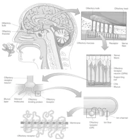
In order to discuss various components of the biological olfactory system, an
anatomy of the human olfactory system is shown in Figure 1.1 [2]. In the human
olfactory system, odours are delivered through the nasal passages to the olfactory
epithelium where various olfactory receptors are located. The inhaled odorant
Chapter 1: Introduction 2 2
cavity to reach the olfactory receptor cells, which occupy a small area in the nasal
epithelium[3].
Nasal cavity or ‘Nasal fossa’ is the air filled area located behind the nose in
front of the face. The function of the nasal cavity is to precondition the sniffed air by
warming and humidifying the air in such a way that it prepares the odour before
being sensed and processed [4, 5]. This is a crucial task that assists the olfactory
system to perform better. Furthermore, the vibrissae (short, thick hairs located in
the nasal cavity), clean the sniffed odour by removing dust and other particulate
matter in the sniffed air. The nasal cavity shape allows the odour molecules to
accumulate, concentrating the odour to interact better with olfactory receptors.
Figure 1.1: Anatomy of a Human Olfactory System
The olfactory receptors, located on the surface of the cilia of the olfactory epithelium
[image:16.595.192.452.357.634.2]Chapter 1: Introduction 3 3
micro domains, called glomerulus [6, 7] in the olfactory bulb, the primary olfactory
area of the brain. Receptors have overlapping sensitivity to different odorants, that
is, each of the odorant molecules correspond to an exclusive group of responses
from the receptors. Through the olfactory bulb the information of the vapour will
reach the olfactory cortex and the brain where the information from several
receptors is processed, forming a pattern that can be recognized.
Comparing the olfactory system of humans with other animals, rats are 8 to
50 times more sensitive to odours than humans, whilst dogs are 300 to 10,000 times
more sensitive, depending upon the odorant [8]. The sensitivity of dogs’ olfactory
system is known to be much higher than that of humans[9]. Several factors such as
the size of the olfactory epithelium, the density of neuronal cells and the number of
olfactory receptor as well as the size of the olfactory bulb, contribute to the
sensitivity of mammalian olfactory[10]. The human nose has about 12 million
olfactory receptor cells[11] and 1000 different receptor protein types while dogs
have 1 billion receptor cells. Furthermore, in dogs, 5% of the dogs genome is given
over to smell compared to 1-‐2% in human genome. Thus it is clear that the number
of olfactory receptor cells contributes to the sensitivity of the olfactory system. The
reason why a number of sensors are so important is that it increases the diversity of
detection, meaning we can get more information from the array, thus detecting
more different odours.
1.1
Electronic noses
The research into an artificial bio-‐mimetic mammalian olfactory system has been an
active research area over 20 years, since the idea first came to light in 1980[12].
Chapter 1: Introduction 4 4
conceptualization of the electronic nose[13]. The term electronic-‐nose first appears
in 1988 [14]; it was later defined formally by Gardner et al. [1] where he defines it as:
‘Electronic Nose as an instrument, which comprises an array of electronic chemical sensors
with partial specificity and an appropriate pattern-recognition system, capable of recognising
simple or complex odours’.
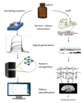
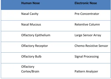
Figure 1.2: (a) Electronic Nose versus (b) Human Olfactory System
Figure 1.2 shows the comparison of a human olfactory system and an electronic nose
pathway [15]. In a human olfactory system, when a human sniffs an odour, the
olfactory receptor neurons generate a signal and send it to the brain to be identified.
[image:18.595.192.454.264.595.2]Chapter 1: Introduction 5 5
electronic nose. The signal from these chemo-‐sensors will be fed to a pattern
recognition system where it will be recognized and identified. Here we can see that
we are able to simulate human olfactory system with two main parts, the sensing
part which is mimicked by an array of chemical sensors and the second is the pattern
recognition system emulating the olfactory bulb to process the data.
Throughout the years, researchers have come up with different techniques of
discriminating and recognizing odours, all with their own advantages and
disadvantages. Some researchers have focussed on the chemical sensor array itself
while others try to improve the electronic nose (e-‐nose) by improving the processing
technique. Both of these areas are equally important in creating a better electronic
nose system. Some research has focussed on developing new e-‐nose instruments by
adding an ‘enhancement’ to their system, such as SPME, preconcentrator or gas
chromatograph [16]. Here we will discuss two approaches of improving electronic
nose instruments focussing on sensor-‐based gas detectors and instrument based gas
detectors that employ different detection mechanisms.
1.2.1 Sensor-based gas detectors
A sensor is a device that measures a physical quantity and converts it into a signal,
which is readable by an observer or instrument. Hence, a chemical sensor changes
some physical or electrical property of itself through chemical reaction when
exposed to a reactive gas or vapour.
Sensor-‐based electronic noses basically consist of some type of sensor with a
fluidic system of pumps and valves. The sensors (usually in an array) are interfaced to
a signal conditioning and data acquisition circuit to collect data from the sensor. This
Chapter 1: Introduction 6 6
based) for classification or discrimination. The sensor array, which is the central of
the e-‐nose instrument, utilizes different methods of detecting gas using various
principles.
An ideal gas sensor would respond to odour molecules even in low
concentrations and also change linearly with the concentration until it reaches
saturation. In addition, it should respond and recover quickly to the original value
once the odour source is removed. Other desired characteristics also include great
reproducibility, wide working range and steady baseline.
In comparison, real sensors suffer from baseline drift, sensor poisoning and
sensitivity changes depending on the ambient condition, such as humidity,
temperature and flow rate. These are the factors that need to be improved in order
to get a better response from the gas sensor.
A nose sensing capability can be realized using various technologies including
conductometric chemo-‐sensors (metal oxide semiconductors[17], carbon black
composite and conducting organic polymers[18]), chemo-‐capacitors, potentiometric
chemo-‐sensors (e.g. MOSFET), gravimetric chemo-‐sensors (QCM[19], SAW), optical
chemo-‐sensors (SPR, fluorescent sensors, NIR), calorimetric sensors, and
amperometric sensors [3]. Electrochemical sensor is a popular types of method used
by many researchers. Gardner et al describe the application of conducting polymers
for electronic nose [20] and Persaud et al use the conducting polymer sensor arrays
to identify a few types of chemicals in their research [21]. Many researches now
focus on using different types of gas sensitive material to improve sensitivity and
selectivity of the gas sensor. Figure 1.3 shows various commercially available
Chapter 1: Introduction 7 7
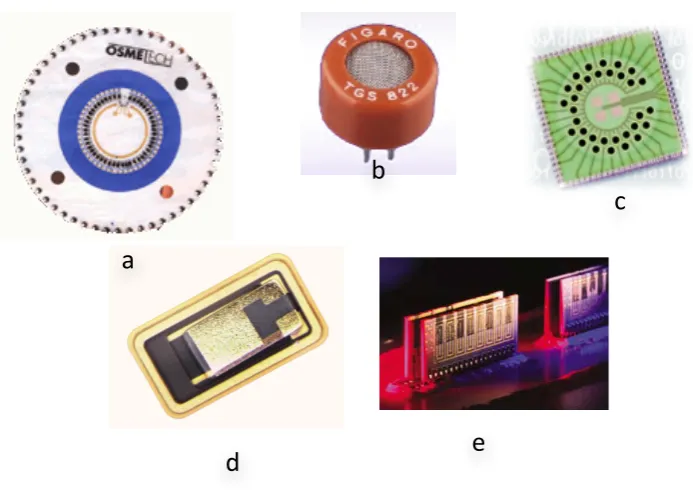
Figure 1.3: Sensor Technology. a) Osmetech 48 Conducting Polymer sensors b) Figaro TGS 822 Tin Oxide sensors c) Smiths Detection (previously known as Cyrano Sciences) 32-‐sensor
integrated array d) Polymer based chemoresistive sensor from Osmetech e) NASA 32 integrated sensor array
The various chemo sensors can also be categorized by the sensing material used
alongside the sensing technique, for which the following exists: metal oxide (MOS),
conducting polymers (CP), Carbon Nanotubes (CNT), Carbon Black Composite (CB),
and Organic Conducting Polymer(COP). A more recent discovery on nanomaterials
brings a whole new possibility for electronic nose instruments. Various researches
have shown the ability of nanomaterials as gas sensors [22-‐25]. Table 1.1 shows the
different techniques with the advantages/disadvantages of each method.
a
b
c
[image:21.595.113.460.92.337.2]Chapter 1: Introduction 8 8
Table 1.1: Various Sensor Types with advantages and disadvantages
Sensing Technique Sensor Type Advantages Disadvantages References
Carbon Black Composite
Room
Temperature, diverse range of coating
[image:22.595.107.537.116.559.2]Sensitive to humidity / small response
[26, 27]
Conducting Polymer
Cheap, good response time, sensitive to polar analytes
Suffer from baseline drift, sensitive to humidity
[28] Conductometric
Metal Oxide Fast response and recovery time, cheap
Operates at high temperature
[28]
SAW High sensitivity,
good response time
Poor
reproducibility
[29] Mechanical
QCM Diverse range of
coating, Good reproducibility
Complex circuitry, poor SNR
[19, 28]
Thermal Pellistor
Thermocouple
Low Cost Slow Response [30]
Radiation FIbre Optics Fast Response,
not susceptible to electromagnetic
Expensive [28, 31]
1.2.2 Instrument-based gas detectors
Conventionally, a different type of approach is used as a method for analyzing the
composition of a gas or vapour. One of the most common instruments is the Gas
Chromatography (GC). GC uses a different approach in detecting gases compared to,
for example, solid-‐state chemo sensors used in an electronic nose. With GC, the
Chapter 1: Introduction 9 9
a detector on the outlet. An electronic nose on the other hand, detects the gas as a
whole and the pattern recognition method will classify or discriminate the odour.
Various sensors can be use along side a GC to detect the separated gases, such as
discharge ionization detector (DID), electron capture detector (ECD), flame
photometric detector (FPD), flame ionization detector (FID), Hall electrolytic
conductivity detector (ECD), helium ionization detector (HID), Nitrogen Phosphorus
Detector (NPD), mass selective detector (MSD), photo-‐ionization detector (PID),
pulsed discharge ionization detector (PDD) or thermal energy(conductivity)
analyzer/detector (TEA/TCD) . There are also some studies suggesting employing gas
sensors used in electronic noses, for such detection purposes [32, 33].
Figure 4 : a) HP 6890 Series Gas Chromatography b) zNose 4500[34]
The main problem with conventional GC techniques is the slow analysis time.
An example is the HP 6890 series GC (Figure 4(a)) which takes 20-‐120 minutes per
analysis cycle. It is also very bulky, laboratory based, and too costly to be used on-‐
site. Hence, the need for faster chromatogram arises. The first realization of a fast
Chapter 1: Introduction 10 10
carbon disulfide, methanol, and methylene chloride in less than 10 seconds [35]. A
bigger breakthrough than the fast separation was the fact that Golay used a 32 ft
long, 254 μm diameter thin film capillary column instead of a packed column
commonly used at the time. The fast GC has developed tremendously since then.
Now research shows a column less than a meter long with the size 2.4 cm x 4 cm, is
able to separate complex odour within a few seconds [36]. Sandia Labs have
demonstrated a 2d multidimensional GC just a meter long, smaller than a dime,
separating 5 different vapours in less than a minute [37]. The zNose from Electronic
Sensor Technology shown in Figure 4(b) is able to detect vapour at part per
billion(ppb) level in just 10 seconds (though this does not include the 5 minutes for
the pre-‐concentration stage) [34].
Mass spectrometry is another common analytical method for detecting
odorant compounds. This technique separates molecules by ionisation and then
separating the ions in the mass spectrometer (MS) according to the mass-‐to-‐charge
ratio of the ion [1]. Smart Nose is a commercial example of an e-‐nose utilizing MS
methods. The combination of Gas Chromatography with Mass Spectrometry (GC-‐MS)
is a very popular technique for identifying volatile compounds. Many research have
utilized GC-‐MS combination to analyze vapour[38-‐42].
Another method for identification is called Ion Mobility Spectrometry(IMS)
where it is based on the ionization of gas or vapor molecules under atmospheric
pressure followed by the drift of the resulting ions in an accelerating electric field.
The velocity of the ions depends on mobility coefficients, which in turn are
determined by ion masses and other properties. Different ions reach the detector at the
Chapter 1: Introduction 11 11
1.3
Commercial Electronic Nose
The first commercial version of electronic nose came out in the mid-‐1990s [43] with
the Fox 2000 from Alpha MOS. The main application areas were in the food
industries. The advancement in industries calls for a commercial intelligence vapour
analyzing device. Some commercial instruments have been given in the following
table (Table 1.2).
Table 1.2: Commercial E-‐Noses
Device Manufacturer Sensor
Type
Sensors Number
Size
Fox 2000,3000,40000 Alpha MOS MOS/SAW 6,12,18 Desktop
z-‐Nose 4500 EST GC/SAW 2 Laptop
BloodHound ST214 University of Leeds Innovation Ltd
CP 14 Laptop
Heracles Alpha MOS GC-‐MS -‐ Desktop
SMart Nose SMart Nose Inc. MS -‐ Desktop
Cyranose 320 Smith Detection Carbon
Black
32 Portable
PEN-‐2 WMA AIRSENSE ANALYTICS MOS 10 Portable
HAZMATCAD, CW Sentry 3G
Microsensors System SAW -‐ Portable
SensorFreshQ FQSI -‐ -‐ Portable
LibraNose TECHNOBIOCHIP QCM 8 Portable
e-‐Nose 5000 Marconi Applied CP 12 -‐
[image:25.595.108.538.274.733.2]Chapter 1: Introduction 12 12
More than 10 companies have developed their own version of e-‐Nose ranging from
handheld to desktop size instruments. Various methods of detection are used with
their own advantages/disadvantages. When discrete sensor arrays are used in e-‐
noses, then the number sensing elements range from 2 to 32 sensors. The e-‐nose
has even gone into the consumer market with the development of SensorFreshQ
from FQSI, which can determine the freshness of meat or poultry in less than a
minute.
First commercial handheld electronic nose by Cyrano Science (USA) employed
a 32 carbon-‐black polymer composite sensor array, which was designed for on-‐site
applications. Cyranose 320 has proven to be a popular e-‐nose used in many
researches[44-‐46], probably due to its low unit cost and small size making it easier to
be used on-‐site use.
1.4
Applications of electronic noses
Although current electronic nose technology still lags far behind the human olfactory
system in term of selectivity and sensitivity, it is still being used in a wide range of
applications, in several industries such as environmental, the food industry and in
the medical field. The main reason for this is the ability of an electronic nose to solve
specific problems at a lower cost within a shorter period of time. Using humans to
evaluate the smell of products such as perfumes, foods and beverages is a costly
process, because trained panels of experts are required and they can only work for
relatively short periods of time. This topic will discuss several industrial applications
Chapter 1: Introduction 13 13
One of the first markets for electronic noses was in the food industry [47].
Electronic noses are used for the inspection of food quality, control of food cooking
processes [48] and quality assessment of food production [47]. Even consumer level
e-‐noses have been developed for the food industry such as the SensorFreshQ. It
detects the freshness of meat by identifying the odour released by bacteria growing
on the meat. The bigger the colony of bacteria, the stronger the smell will be. In the
area of environmental monitoring, the application of electronic noses includes
analysis of fuel mixtures [49] and detection of oil leaks [50]. Significant research has
been undertaken in the area of Biomedical Engineering. Recent development in
biomedical engineering using electronic noses includes the detection of
Mycobacterium tuberculosis (TB) [51], screening of aroma-‐producing lactic acid
bacteria [52] and monitoring of Haemodialysis [53]. The electronic nose is also used
in the brand identification of cigarette [54] and paper quality [55]. As we can see, the
electronic nose has been applied to a wide area of applications. Despite this growing
number of applications, there is still much work required to realise its full potential.
There are currently many limitations to current commercial instruments including
high cost (Fox 2000 cost around £40,000), large size and weight, humidity and
temperature dependence, poor reproducibility and repeatability, high power
consumption, and long analysis time [15]. At present, odour-‐sensing applications
demand high levels of system sensitivity and stability. Traditional engineering
approaches have not yet obtained this kind of sensitivity and stability.
Chapter 1: Introduction 14 14
1.5
Research objectives
The mammalian olfactory system is far superior compared to any sensing
technique available today in indentifying and discriminating odours. However, as
discussed in this chapter, presently available instrument are good enough to solve
problems in various areas. More research is being done to improve the performance
of an electronic nose to bring it close to the mammalian nose. This research focuses
on extracting engineering design principles in the mammalian nose and mimicking
that design in an artificial nose. As discussed in previous topics, the mammalian nose
is many times more sensitive and has the ability to discriminate more different
odours, over traditional electronic noses. This is due to the huge number of
receptors cells in the mammalian olfactory system. The research undertaken here
will try to more closely mimic the mammalian system by developing electronic nose
instruments that have significantly higher sensor numbers, compared to present
commercial instruments. In addition, we will use many different sensor tuning
(equivalent to different binding proteins in the mammalian system). Ultimately, a
larger sensor count with a wider range of tunings provides more data for processing,
thus increasing the selectivity of an electronic nose.
Another principle from the mammalian olfactory system that will be
deployed in this research project is a replication of the nasal mucosa function. As
mentioned before, the nasal mucosa acts as a separator to separate complex odours
to make it easier for the olfactory system to process the information. It is not
proposed to create a full ‘gas chromatograph’ system, as the mammalian system
Chapter 1: Introduction 15 15
Finally, with large sensor arrays mimicking the large olfactory receptor, and the
retentive channel to mimic the nasal cavity, a portable e-‐nose instrument based on
the mammalian nose principles is produced. This portable e-‐nose instrument is then
tested to detect some complex odour to prove its functionality.
1.6
Outline of thesis
The thesis describes the design, development and characterisation of a novel
instrument that mimics more closely the mammalian olfactory system towards
developing a new generation of portable electronic noses.
Chapter 1 reviews the biological olfactory system and electronic nose instruments
comparing their differences and similarities. It also discusses the main application
areas of the electronic nose instruments. The aims and objectives of the thesis are
then presented.
Chapter 2 describes the project evolution; understanding the olfactory principles to
be applied in an artificial nose.
Chapter 3 and 4 cover the design and development of two of the Important
components, the sensors array and the microchannel packages.
Chapter 5 discusses the fusion of sensor array and microchannel packages to
produce an Electronic Mucosa System. Polymer deposition and stationary phase
deposition are also covered here.
Chapter 6 describes development of the portable electronic system which combines
Chapter 1: Introduction 16 16
Chapter 7 reports the characterisation results of the fabricated microsystems to
evaluate their performance. The central focus here has been geared towards getting
spatiotemporal signals from these systems and the benefit of these signals to aid
discrimination.
Chapter 8 concludes the research and the latest developments are presented to
highlight possible future enhancements.
1.7
References
1. J. W. Gardner , P.N.Barlett., Electronic Noses : Principles and Applications. First ed. 1999:
Oxford University Press.
2. E.B Goldstein , Sensation and perception. Sixth ed. 2002: Wadsworth Inc Fulfilment.
3. T.C. Pearce, H. T.Nagle, J.W. Gardner, Handbook of Machine Olfaction. 2003: Wiley.
4. J.T. Kelly,A.K. Prasad, and A.S. Wexler, Detailed flow patterns in the nasal cavity. J Appl
Physiol, 2000. 89(1): p. 323-‐337.
5. G.M Shepherd, The Human Sense of Smell: Are We Better Than We Think? PLoS Biology,
2004. 2(5): p. e146.
6. K.J.Ressler, S.L.S., L.B. Buck, Information coding in the olfactory system: Evidence for a
stereotyped and hihly orgnized epitope map in the olfactory bulb. Cell, 1994. 79: p. 1245.
7. L. Buck , R.Axel., A novel multigene family may encode odorant receptors: A molecular basis
for odor recognition. Cell, 1991. 65: p. 175-‐187.
8. D.G Laing, R.L.D., W. Breipohl, The human sense of smell. 1991, New York: Springer.
9. S.B Rouquier, D. Giorgi , The olfactory receptor gene repertoire in primates and mouse:
evidence for reduction of the functional fraction in primates. . Proc Natl Acad Sci, 2000. 97: p. 2874.
10. P. Quignon,et al., Comparison of the canine and human olfactory receptor gene repertoires.
Genome Biology, 2003. 4(12): p. R80.
11. D.Shier, J. Butler, R. Lewis, Hole's Human Anatomy & Physiology. 2004, Boston: McGraw Hill.
12. H.Zwaardemaker, a.F.H., On spray-‐electricity and waterfall-‐electricity. Proc. Acad. Sci. Amst.,
1920. 22: p. 429-‐437.
13. K Persaud, , Analysis of discrimination mechanisms in the mammalian olfactory system using
a model nose. Nature, 1982.
14. J.W.Gardner, Pattern recognition in the Warwick electronic nose. 8th International Congress
of the European Chemoreception Research Organisation, 1988.
15. T.A.Dickinson Current trends in ‘artificial-‐nose’ technology. TIBTECH, 1998. 16.
16. rsquo, et al., A comparison of warmed-‐over flavour in pork by sensory analysis, GC/MS and
the electronic nose. Meat Science, 2003. 65(3): p. 1125-‐1138.
17. B.K Dable, et al., Calibration of microhotplate conductometric gas sensors by non-‐linear
multivariate regression methods. Sensors and Actuators B: Chemical, 2004. 101(3): p. 284-‐ 294.
18. A.L. Kukla,et al., Application of sensor arrays based on thin films of conducting polymers for
chemical recognition of volatile organic solvents. Sensors and Actuators B: Chemical, 2009.
135(2): p. 541-‐551.
19. Y.Han Kim, and K. Jae Choi, Fabrication and application of an activated carbon-‐coated quartz
crystal sensor. Sensors and Actuators B: Chemical, 2002. 87(1): p. 196-‐200.
20. J.W.Gardner, Application of conducting polymer technology in Microsystems. Sensors and
Actuators A, 1995. 51.
21. K.C.Persaud, Sensor array techniques for mimicking the mammalian olfactory system.

![Figure
3.7:
Gold
resistivity
vs
Temperature [9].](https://thumb-us.123doks.com/thumbv2/123dok_us/9728010.473751/61.595.116.528.200.441/figure-gold-resistivity-vs-temperature.webp)