© 2019, IRJET | Impact Factor value: 7.34 | ISO 9001:2008 Certified Journal
| Page 2001
Waveform Generation using Direct Digital Synthesis (DDS) Technique
Yashas S R
1, Sutej Kulkarni
2, Mr. Bharath Kumara
31,2
Student, Electronic and Communication Engineering, Ramaiah University of Applied Sciences,
Bengaluru, 560058, INDIA
3
Mr
.
Bharath Kumara: Assistant Professor, Dept. of Electronic and Communication Engineering,
Ramaiah University of Applied Sciences, Bengaluru, 560058, INDIA
---***---Abstract –Waveform generators are widely used across manyapplications. Mainly, these sort of waveform generators are used in Signal Generation for the laboratory experiments conducted in school and college laboratories. A lot of these waveform generators are also used in design and testing of Integrated circuits, microcontrollers and many other end-user products like water level controller, thermostat to mimic the effects that they would experience in the real world.
The waveform generators in the current market cost a lot of money, which many people cannot afford. This paper describes the process involved in constructing a signal generator using a Direct Digital synthesizer.
Key Words: Function generator, Waveform generator, Direct Digital Synthesizer (DDS), Operational Amplifier (Op-Amp), Digital to Analog converter (DAC)
1. INTRODUCTION
Integrated Circuits have played a huge role in making lives easier. Amp is a DC coupled amplifier with high gain. Op-amps are used for many applications such as low voltage amplification, Voltage adders, subtracters, multipliers, differentiators, integrators. They are also used for applications such as filters, oscillators, Data converters (DAC), comparators, etc.
A digital to analog converter (DAC) is block which converts digital binary data to its corresponding analog form.
Signal generators currently in the current market is very costly. So, if an equipment gets some fault, it becomes hard to repair. Hence, a cost-effective method is required by us.
Direct Digital Synthesis (DDS) is a frequency synthesizer method that is used in waveform generation. Using this technology, it is possible to design a waveform generator which is compact and has great efficiency.
The output produced by this technique includes sine, square, triangular and sawtooth waves, which can be tuned accordingly with high accuracy in amplitude and frequency, enough for educational purposes
[image:1.595.324.541.211.388.2]The different types of waveforms that can be generated using DDS Technique is as follows,
Figure 1: Different types of waveforms generated
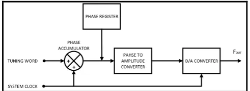
2. Direct Digital Synthesizer (DDS)
[1] DDS is a method of generating different Analog waveforms using digital techniques. It operates by saving the points of a waveform in its digital form. Then it reconstructs the waveform by recalling these digital data. It is a technique which uses digital data and analog signal processing blocks to generate signal waveforms that are repetitive in nature. Many years ago, these digital synthesizers were limited by the clock frequency, which would hinder the speed of operation of the digital logic. Now, with increasing frequency, the limits of the DDS are also increasing.
The Direct Digital synthesizer basically has a system clock signal generator, which is cascaded with a waveform mapper and an input. According to this input, the waveform mapper generates digital data according to the phase and frequency component of the analog signal to be generated. This is then fed to a DAC to get the analog signal. Before sending out the data, it passed through a low pass filter to eliminate the noise components from the DAC and to do some wave shaping.
PAHSE TO AMPLITUDE CONVERTER
D/A CONVERTER PHASE REGISTER
+ +
PHASE ACCUMULATOR
SYSTEM CLOCK
FOUT
TUNING WORD
[image:1.595.311.557.661.751.2]© 2019, IRJET | Impact Factor value: 7.34 | ISO 9001:2008 Certified Journal
| Page 2002
2.1 Signal generationDDS consists of digital processing to generate signals of different frequencies and phases. This can be selected digitally, from a reference system clock. The number of bits of the DDS and the desired output signal frequency is given by:
f
0=M*(clock frequency)
(2^N)
Where, fo = Signal frequency
M= Tuning word
N= Number of bits of the phase accumulator.
DDS has quick frequency response, improved phase noise, and precise control of the output phase across frequency switching transitions. The output frequency of a DDS is determined by the value stored in the frequency control register.
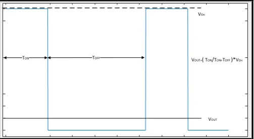
The Pulse with modulator generates fixed period square waves by changing the duty cycle ratio. Higher the duty cycle rate, implies that signal has a higher output voltage. This voltage value is shown in:
TON
VOUT
VOn
[image:2.595.306.563.306.419.2]VOUT=( TON/TON+TOFF )*VOn
Figure 3: Pulse Width Modulated (PWM) Output
Von is the upper value of the PWM signal. The parameter τon is the time that the square wave remains at the maximum level and τswc is the period of the square wave. It is necessary to increase the frequency of the PWM signal be able to provide higher frequencies. This means an extra cost.
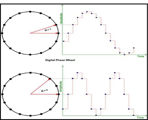
In the DDS method, more accurate and faster results are obtained. Figure 2 shows the DDS block
The synthesizer operates by storing various points in the waveform in digital form and then recalling them to generate the waveform. Its operation can be explained in more detail by considering the phase advances around a circle. As the phase advances around the circle this corresponds to advances in the waveform, i.e. the greater the number corresponding to the phase, the greater the point is along the
waveform. By successively advancing the number corresponding to the phase it is possible to move further along the waveform cycle.
Step values in the circle is recorded up to decimal point. Each recorded value is routed to ports of waveform mapper. The change in signal frequency depends on the change in the values from the synthesizer.
2.2 Digital to Analog Converter
Maximum output voltage is 5v. Output voltage is formulated below. We denote Vref as the maximum voltage from the port and VAL as digital data that the microprocessor applies to the DAC module, and N as the number there is apply to the DAC module.
Vout = Vref × VAL / 2N
R R R
2R 2R 2R 2R
2R
2R MSB
LSB
[image:2.595.38.290.409.547.2]VOUT
Figure 4: R-2R Ladder DAC Circuit
2.3 Low pass filter
DS1868-10 is a digital potentiometer integrated which is utilized to validate the output signal. Digital code of the signal in the synthesizer is sent to the DAC and DS1868-10. Output resistance and the voltage change proportionally to Digital data that has been sent to DS1868-10. These data are checked against the output signal by applying them to the analog entry of the controller. The resistance interval of DS1868-10 integrated is measured by dividing resistance value to 256.
3. Advantages of Digital Synthesizer method
Advantages of Direct Digital Synthesizer are:
• The frequency is tunable with very high resolution.
• The phase is digitally adjustable.
• Conceptually simple design & cost effective
• No drift due to temperature changes or component aging (as long as the clock is stable).
© 2019, IRJET | Impact Factor value: 7.34 | ISO 9001:2008 Certified Journal
| Page 2003
The sine waves can be generated at nearly half the clockfrequency. It can also generate a square wave from a sine wave when amplitude. However, maintaining the fidelity of a square wave is harder because of the rich harmonic content – the post – processing circuitry needs to be of a higher bandwidth than for a single sine wave. Thus, it is not uncommon to see the square wave maximum frequency to be half or less of the sine wave maximum frequency. A similar comment applies for pulse generation, where the spectrum requirement can be even more demanding.
Some synthesizer provides specialized waveforms as added features. These are addition functions f(ξ) that are stored in the generator read only memory they can be useful for specialized task. Since these specialized waveforms need to be generated accurately. Their maximum output frequency will often be much less than the typical sine & square wave frequencies available from the generators.
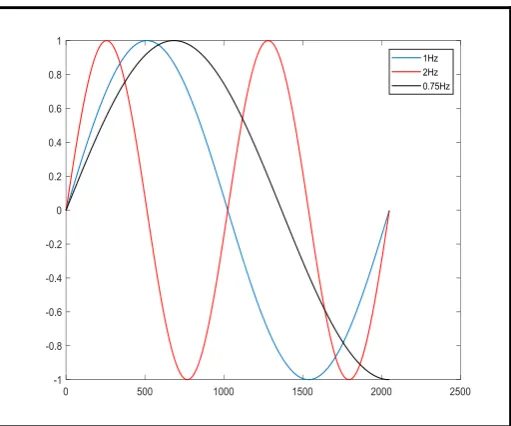
4. MATLAB code for DDS
We can demonstrate the generation of sine waves for DDS using MATLAB:
sintablen = 2048;
SINTAB = sin(2*pi*(0:sintablen-1)./sintablen); fs = 2048;
% the sintable consists of one cycle of sine wave with 2048 samples
% if you access 2048 samples/sec (fs) from the above sintable,
% it will generate one complete cycle of sine wave in one sec. % so, effectively the frequency is 1Hz.
% step = 1; Feff(Effective frequency) = fs/sintablen;
F_required = 1;
index = 1; step = (F_required/fs)*sintablen; for i = 1:2048
sin1Hz(i) = SINTAB(round(index)); index = index+step;
if index>sintablen
index = index-sintablen; end
end
plot(sin1Hz); hold on;
% suppose we need to generate 2Hz sine wave. % step = 2;
F_required = 2;
index = 1; step = (F_required/fs)*sintablen; for i = 1:2048
sin2Hz(i) = SINTAB(round(index)); index = index+step;
if index>sintablen
index = index-sintablen; end
end
plot(sin2Hz,'r'); hold on;
% suppose we need to generate 0.75Hz sine wave
index = 1;
F_required = 0.75;
step = (F_required/fs)*sintablen; for i = 1:2048
sinp75Hz(i) = SINTAB(round(index)); index = index+step;
if index>sintablen
index = index-sintablen; end
end
plot(sinp75Hz,'k'); hold on; legend('1Hz','2Hz','0.75Hz')
[image:3.595.310.566.506.719.2]The waveforms generated is visualized as follows:
© 2019, IRJET | Impact Factor value: 7.34 | ISO 9001:2008 Certified Journal
| Page 2004
5. Signal flow and functional block diagram of DDSDDS AD9834
LPF DDS
OUTPUT
BUFFER AMPLIFIER
OUTPUT
LOW PASS FILTER OUTPUT
AD8014AR 3 2
4
7
6
R1
C R2
R3 VCC
5.0V
R4
DDS BLOCK BUFFER AMPLIFIER BLOCK
[image:4.595.37.291.112.251.2]LOW PASS FILTER BLOCK
Figure 6: Block diagram of Waveform Generator
[image:4.595.37.289.400.515.2]The main components of DDS are a phase accumulator, phase-to-amplitude converter (a sine look-up table), a Digital-to-Analog Converter and filter. A DDFS produces a sine wave at a given frequency. The frequency depends on three variables; the reference-clock frequency and the binary number programmed into the phase register (frequency control word, M), length of n-bit accumulator. The binary number in the phase register provides the main input to the phase accumulator
Figure 7.a: Phase relationship for a signal
Figure 7.b: Phase relationship for a signal
6. Integrated circuit for DDS
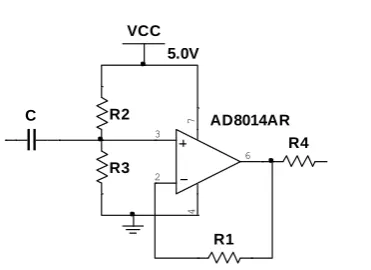
The AD9834 is a 75 MHz complete low power (20 mW) DDS. It is designed to provide accurate and complementary current outputs up to 4 mA with frequencies of output, up to 37.5 MHz. The AD8014 is a high-speed current feedback amplifier with 400 MHz, −3 dB bandwidth, 4000 V/μs slew rate, and 24 ns settling time. It has extremely low voltage and current noise as well as low distortion. The low power (5.2 mW at +4.5 V), low cost, and 30 mA current drive capability make the AD8014 an attractive solution as a buffer for the AD9834 output. The circuit operates on +3.3 V for the AD9834 and +4.5 V for AD8014. The DDS operates with an SPI interface. The circuit consists of three blocks: the DDS block, the buffer block, and the low-pass filter block. Total power dissipation for the circuit is about 25 mW.
DDS Voltage Output
The full-scale adjust (FSADJUST) voltage and the external resistor, RSET, determine the magnitude of the full-scale DAC current. The FSADJUST has a nominal value of 1.15 V, while the RSETresistor has a typical value of 6.8 kΩ.
The full-scale current of the AD9834 is as follows:
IFULLSCALE = 18 × (FSADJUST/RSET)
This circuit uses a specified load of 200 Ω and maximum full-scale current to achieve voltage output without exceeding the compliance range of the DAC.
IFULLSCALE = 18 × (1.15/6800 Ω) = 3 mA,
VOUT = 3 mA × 200 Ω = 0.6 V
There are two current outputs available: IOUT and IOUTB. The IOUT is unfiltered, and the IOUTB is filtered.
Buffer Amplifier
[image:4.595.36.287.542.745.2]© 2019, IRJET | Impact Factor value: 7.34 | ISO 9001:2008 Certified Journal
| Page 2005
AD8014AR
3
2
4
7
6
R1
C R2
R3 VCC
5.0V
[image:5.595.79.265.85.220.2]R4
Figure 8: Buffer amplifier circuit using AD8014
Low Pass Filter
The anti-imaging reconstruction must attenuate the image frequencies inherent to a sampled system.
There are four basic filter types that can be used as a reconstruction filter: Cauer Elliptic filter, Chebyshev filter, Butterworth filter, and Bessel filter.
With higher order, we get better results from the filter. But the drawback is some phase shift in the results.
7. Limitations of the IC
When the resolution of the signal to be generated changes, there are some noise generated in the output
UHF frequencies cannot be generated in this DDS IC.
8. CONCLUSIONS
We have described a method of waveform generation using a method called Direct Digital Synthesis. There are many other ways of generating waveforms, other than this method, which is used in the current signal generators in the market.
Using DDS, we can generate different types of waveforms like sinusoids, square waves, triangular waves etc. from a single block. This is possible using
REFERENCES
[1] James M. Fiore, Operational Amplifiers and Linear Integrated Circuits: Theory and Application, 3rd Edition
[2] Low Cost Laboratory Type Signal Generator Using DDS Method, Süleyman Bilgin, Yavuz Üser and Mustafa Oktay, IJEAS
[3] Low-Cost Arbitrary Waveform Generator for Educational Environment Using ARM7, Nandkishor Gupta, Prashant Sediwal, Prabhat Pandey, IJERA
[4] Mr. Mani Dargahi Fadaei,(2013) A Low-Cost Programmable Arbitrary Function Generator for Educational Environment
[5] R. Pandey, N. Pandey, S. K. Paul et al., “Voltage mode astable multivibrator using single CDBA,” ISRN Electronics, vol. 2013, Article ID 390160, 2013.
[6] G. Zhang, “Research of DDS-based high-precision multichannel signal generation systems,” Electronic Measurement Technology, vol. 37, 2014.
[7] Y. Sun, J. Lu, S. Liu, and H. Ben, “Design of sinusoidal signal generator based on AD9833 and potentiometer,” Electrical Measurement & Instrumentation, vol. 7, 2012.
[8] D. Yang, X. Yang, and J. Chen, “Design and implementation of direct digital frequency synthesis multiple signal generator based on FPGA,” Journal of Xi’an University of Technology, vol. 4, 2013.
[9] J.Vankka and K.Halonen, Direct Digital Synthesizers: Theory, Design and Applications. Norwell, MA: Kluwer, 2001.
[10]Jian Qi, Qun Sun, Xiaoliang Wu, Chong Wang and Linlin Chen, Design and Analysis of a Low Cost Wave Generator Based on Direct Digital Synthesis
*All waveforms are generated using MALTAB