A Storage Architecture for High Speed Signal Processing:
Embedding RAID 0 on FPGA
Ningxiao Sun, Qiongzhi Wu, Zhaojian Jin
School of Information and Electronics, Beijing Institute of Technology, Beijing, China. Email: [email protected]
Received April 20th, 2012; revised May 25th, 2012; accepted June 10th, 2012
ABSTRACT
The article proposes a new architecture based on RAID 0 tech in computer science for signal processing field to store high speed data. It is composed of SSD driven by FPGA, called SSD-based RAID on FPGA. This new architecture fea-tures high storage rate, mass capacity and small volume, and it is an efficient solution to store high speed data. The arti-cle describes the construction of SRF in details, and shows the test result of a demo system based on the architecture.
Keywords: RAID on FPGA; SSD; High Speed Data Storage
1. Introduction
In signal processing field, the system designer has been greatly forced to choose between real-time processing and the storage capacity of the acquisition signal. In the past, the latter always limits the maximum count rates supported without data loss. Systems which could per-form both functions at the same time were usually too costly and complex. To solve these problems the first target is to find a sort of the storage medium [1].
Now, with recent advancements in the computer in-dustry, the cost of NAND flash memory becomes lower and the density of NAND flash memory grows larger, the mass-production of solid state drives (SSD) based on NAND flash memory was launched on a full scale [2]. SSD is strong in shock and its I/O performance is better comparing with the conventional hard disk drive (HHD).
Though the storage rate of SSD increases remarkably compared to HHD, SSD alone is hard to meet most re-quirements of data acquisition and storage system [3,4]. Therefore, RAID 0 tech in computer science is intro-duced, and we propose an architecture of RAID, which is based on SSD and driven by FPGA, called SSD-based RAID on FPGA (short for SRF), which features mass capacity, high rate and small volume. In addition, in or-der to save costs, the architecture of SRF is designed to be adjustable in storage rate and capacity.
2. Architecture of SSD-Based RAID on
FPGA
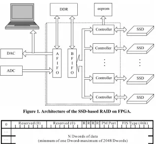
Figure 1 depicts the architecture of the SSD-based RAID
on FPGA.
2.1. SSD Controller
SSD controllers, which directly determine whether the SSD-based RAID is good or bad, are the core of the ar-chitecture. Now, most SSD adopt SATAII with the line rate of 3.0 Gbps. Therefore, the core task is to design a SATA controller applying to SSD.
The physical connection of SATA could adopt the modules of speed serial interface given by FPGA manu-facturers, such as ROCKET IO or Gbps transceivers. These modules with OOB signal for SATA physical layer have an amazing line rate, over 10 Gbps. In addition, there is the 8b/10b coding in the modules to simplify the de-sign of the SATA controller. In respect of clock process-ing, the modules differentiate the clock used by trans-ceivers from the clock of the logic to avoid the occur-rence of interfeoccur-rence. There are more than 20 modules of speed serial interface in current top-end FPGA chips, and it’s the precondition for building up the large RAID.
SATA data transmission adopts Frame Information Structure (FIS), and Figure 2 presents the DATA FIS. According to the protocol of SATA, a DATA FIS con-tains a maximum of 2048 Dwords, i.e. 8 kB data. The method of transmission chooses the command of WRITE/READ DMA EXT through which SSD can read or write 4096 DATA FIS, i.e. 32 MB data [5-7]. And the command of WRITE/READ DMA EXT can greatly re-duce the time in writing or reading SSD.
Figure 1. Architecture of the SSD-based RAID on FPGA.
Figure 2. The data frame information structure.
[image:2.595.309.536.433.542.2]order to accelerate the rate, TRIM command, which can erase the specific sector, is added to ATA8. In SSD- based RAID system, TRIM command should be exe-cuted before the writing operation.
Table 1 shows the test result of a demo SSD controller
for a 256 GB SSD.
From the result, it can be seen that the writing rate of SSD drops as the data quantity grows, but still over 200 MB/s. The explanation for this, is that there is a buffer memory in SSD. The writing rate is limited by the buffer memory when the data quantity is small. As the data quantity grows, the writing rate declines. However, the reading rate of SSD isn’t affected by the data quantity, and maintains at a level of, approximately, 224 MB/s.
2.2. RAID
The multiple architecture of RAID is used for PC sys-tems. This paper proposes an architecture of SSD-based RAID driven by a single FPGA.
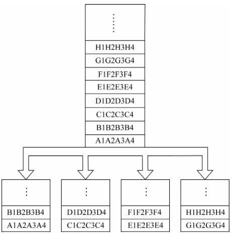
As shown in Figure 3, the data stream is divided into several blocks, and the reading process goes in parallel with the writing process to accelerate the reading or writing rate. If an architecture driven by FPGA adopts this method, the way to improve the writing rate is to increase the quantity of SSD and accelerate the output rate of BFIFO in Figure 2. However, with the increasing
Table 1. The test result of a demo SSD controller.
Data Quantity Writing Rate (MB/s) Reading Rate (MB/s)
32 MB 223 225
512 MB 218 223
2 GB 201 223
48 GB 200 225
250 GB 201 224
quantity of SSD, the number of fan-out of the BFIFO also increases. For high speed data stream of FPGA, having too much fan-out may cause the transmission error. In addition, the logic frequency is limited by the FPGA chip, so the output rate of BFIFO can’t be accel-erated without limits. Therefore, the method which di-vides the data stream is not applicable for RAID driven from FPGA.
Figure 3. Data stream divided by data blocks.
Figure 4. Data stream divided by data bits.
kept at a steady rate, i.e. the interface rate of SATA. To accelerate the storage rate by dividing data bits, the width of BFIFO’s output should be changed with the increasing quantity of SSD.
2.3. Stream Data Buffer
For the signal acquisition and storage system, to avoid the loss of data is the most important thing. However, the transmission of SATA contains redundant data, which vary in each SSD, and the interval between two FIS is hard to be in consistence. Admittedly, some SSD need to wait for others, and data stream has to stop as shown in
Figure 5. To assure data integrity, a large capacity stream
buffer is needed in architecture of SSD-based RAID. After selection, DDR chips are used as the stream buffer. Due to the time difference in reaching the μs-grade, DDR, which usually has tens of MByte, is easy to buffer the data. The number of DDR is determined by the storage rate of the system. In the other words, the reading and writing rate of DDR is at least twice of the storage rate.
2.4. Data Management
Actually, the nature of the storage of acquired data is the storage of stream data. Theoretically, the storage infor-mation needs to record the original position and the quantity of the storage. There are two solutions to the problem of the storage information. One is to store the information in SSD with the acquired data. The other is to store the information in an extra memory chip such as EEPROM or flash memory. The latter is more suitable for the architecture of SSD-based RAID in following aspects. Firstly, when the information is stored in one SSD, there is difference in RAID, which makes it hard for SSD of RAID to perform the unified operation. Sec-ondly, because of the large capacity of SSD, to retrieve information is not an easy task. Thirdly, the stored in-formation can be retrieved without RAID working if an extra memory chip is used. For these three reasons, the architecture should be used in storage of information.
The architecture should formulate the basic unit of storage. For example, the capacity of the storage system
[image:3.595.113.483.601.722.2]is 100 GB, and the user can set 1 GB as the basic unit. It is convenient for the data management system to divide the whole unit into 100 basic units.
3. Test Result of a Demo SRF System
3.1. Test System and Environment
In the test system, there are 18 SATA interface, building a RAID with maximum 18 SSD, and 2 DDR3 as the data buffer. In FPGA, a data generator, referring to the clock of 200 MHz, generates data stream with the width of 160-bits, i.e. the rate of 4 GB/s. The working of genera-tor is controlled by the RAID system. When there is no room to buffer the data in RAID system, the generator is closed, and restarts when there is free space.
3.2. Relationship between the Quantity of SSD and the Storage Rate
The Table 2 shows the relationship between the quantity
of SSD and the storage rate. 1) With the increasing quan-tity of SSD, the storage rate is raising monotonically. 2) The test rate of RAID system does not equal to the ideal rate (the ideal rate = the quantity of SSD * the rate of a single SSD). 3) The gap between the ideal rate and the test rate gets larger with the increasing quantity of SSD.
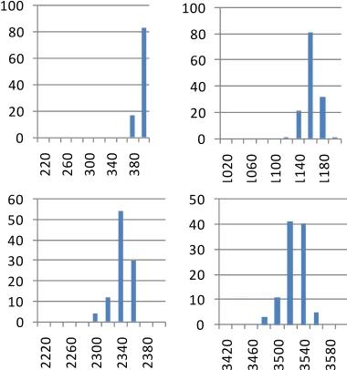
3.3. Probability Distribution of Maximum Rate of RAID
According to the results of the test, it can be found that maximum rate of RAID system isn’t a constant. The
Fig-ure 6 respectively shows four probability distribution of
maximum rate of the demo system with 2, 6, 12 and 18 SSD.
[image:4.595.328.518.87.290.2]According to the results of the analysis, the gap be-tween the test rate and the ideal rate is caused by the dif-ference of each SSD. 1) It is uncertain for each SSD to have the same internal storage rate; 2) The transmission
Table 2. The test storage rate.
Quantity of SSD
Ideal storage rate (MB/s)
Test storage rate (MB/s)
Distance (MB/s)
1 200 200 0
2 400 397 3
4 800 792 8
6 1200 1158 42
8 1600 1557 43
10 2000 1948 52
12 2400 2338 62
18 3600 3528 72
0 20 40 60 80 100 22 0 26 0 30 0 34 0 38 0 0 20 40 60 80 100 10 20 10 60 11 00 11 40 11 80 0 10 20 30 40 50 60 22 20 22 60 23 00 23 40 23 80 0 10 20 30 40 50 342 0 346 0 350 0 354 0 358 0
Figure 6. Probability distribution of maximum rate.
of SATA contains redundant data, and its length is also uncertain for each SSD; 3) Each SSD has different re-sponse time for the instruction. Based on the statement above, admittedly, some SSD has to wait for others. Hence the maximum rate of RAID system is reduced with the increasing quantity of SSD. But, apparently, the increase in number of SSD has the most predominant influence on the rate of RAID system.
4. Conclusion and Discussion
The test on demo system shows that the architecture of SRF has the ability to store high speed data stream and replay the storage data. Although the gap between the ideal rate and the test rate gets larger with the increasing quantity of SSD, it is considered to be within acceptable limits in engineering.
Our future work will focus on quantitative analysis to fit the function between the storage rate of SRF and the quantity of SSD, so that SRF will be applied conven-iently. In the meantime, in order to improve the reliabil-ity, we will update the architecture of SRF based on RAID 4 or RAID 5. Despite the declining storage rate in the situation using RAID 4 or RAID 5 compared to RAID 0, the improvement of reliable is essential to en-gineering.
The architecture of SRF, which features mass capacity, high speed and small volume, will become an efficient solution to storage of broadband signal and high speed data in signal processing field.
REFERENCES
[image:4.595.57.286.569.736.2]Com-munications and Information Technology (ISCIT 2009),
28-30 September 2009, pp. 140-145.
[2] W. F. Jones, “A Digital Architecture for Routinely Stor-ing and BufferStor-ing the Entire 64-Bit Event Acquisition in Clinical Real-Time 3-D PET: Embedding a 400 Mbyte/ sec SATA RAID 0 Using a Set of Four Solid- Solid-State Drives,” 2008 IEEE Nuclear Science Symposium Con-ference, 19-25 October 2008, pp. 5036-5040.
doi:10.1109/NSSMIC.2008.4774371
[3] J. Ren, “I-CASH: Intelligently Coupled Array of SSD and HDD,” The 17th International Symposium on High Per-formance Computer Architecture (HPCA), 12-16 February 2011, pp. 278-289.
[4] W. Wu, “Implementing a Serial ATA Controller base on FPGA,” Computational Intelligence and Design (ISCID
09), Vol. 1, 12-14 December 2009, pp. 467-470.
[5] S. S. Rizvi, “Data Storage Framework on Flash Memory Based SSD RAID 0 for Performance Oriented Applica-tions,” The 2nd International Conference on Computer and Automation Engineering (ICCAE), Vol. 1, 26-28
February 2010, pp. 126-128.
[6] K. R. Dandekar, H. Ling and G. H. Xu, “Smart Antenna Array Calibration Procedure including Amplitude and Phase Mismatch and Mutual Coupling Effects,” IEEE Conference on Personal Wireless Communications (PWC), Vol. 12, 2000, pp. 293-297.