© 2019, IRJET | Impact Factor value: 7.211 | ISO 9001:2008 Certified Journal | Page 3345
ENERGY GENERATION FROM FLYWHEEL USING MAGNET
Aryasree G
1, Evin Jose
2, Jishnu K
3, Jozen Edward
4, Govind Venugopal
51
Assistant Professo, Dept. of EEE, Viswajyothi College of Engineering, M G University, Vazhakulam, Kerala, India
2,3,4,5
Students, Dept. of EEE, Viswajyothi College of Engineering, M G University, Vazhakulam, Kerala, India
---***---Abstract - This project is a developing flywheel energy storage system using magnetic repulsion from sub-scale research prototype to full-scale mechanical flywheel battery and will conduct both a commercial-scale and a utility-scale demonstration. The goal is to deliver a cost-effective and efficient prototype flywheel energy storage system that can be grid connected and also can be used in remote places like islands and the entire system can be electrically charged and discharged with the help of capacitor bank.
The system will have built-in sensing components that can determine frequency and voltage characteristics of the grid and can override the grid signal to manage the amount of electricity discharged. The flywheel starts to rotate when the gear motor rotates as they are magnetically coupled to each other and also with the help of magnetic locking, during this time the flywheel rotates to a specific rpm. Spinning flywheel is coupled with the shaft therefore the synchronous generator is coupled to the shaft using brass couplers and u shaped stand to hold it in place. Thus the rotation taken up by the flywheel rotates the synchronous generator producing electrical energy and this energy is supplied to the capacitor bank and also the LED lamp. The capacitor bank used here is to temporarily store energy and supply it during the time were the flywheel rotation fades. As from this project will improve the traditional flywheel system by engineering breakthroughs in three areas, resulting in higher efficiency and radically reduced cost: magnetic bearings, low-cost rotor, and high-efficiency motor generator. This technology can also be used to optimize existing infrastructure.
Key Words: LED –Light Emitting Diode
1. INTRODUCTION
Overview of the Energy Storage Project Flywheel energy storage te chnology has traditionally focused on storage durations ranging from seconds to minutes. This has primarily been due to two long -standing technical challenges: (1) the traditionally rotor cost, and (2) the potentially high self -discharge rate of flywheel s ystems due to multiple sources of electrical and mechanical loss while operating. In the late 1990s and early 2000s, several well -funded and competent flywheel start -ups worked on commercializing carbon -fibre based rotor designs; however, the projected cos t reduction of carbon-fibre material did not materialize in a
manner which made carbon-fibre based flywheels a cost-effective solution for storage durations above a few minutes. Flywheels subsequently found a comfortable niche in backup uninterruptible pow er supply (UPS) applications where the dominant requirement was high power and low energy. Several years later, other companies advanced flywheel technology by commercializing a flywheel with 15 -minute energy storage duration. However, this target application, frequency regulation, was focused on “power” and “energy” durations; thus, design decisions involving flywheel architecture and material selection were perhaps not focused primarily on the lowest possible cost and lowest possible self-discharge rate.
Here in this paper, we tried to develop a flywheel energy storage system using magnetic repulsion to produce energy in much simpler and economical way. The first idea was to use magnetic bearings and to levitate the entire flywheel in vacuum cham ber, but since it was costly it was dropped. Later we found out that the mechanical bearing can also serve the purpose and the flywheel can be coupled to the shaft. The neodymium magnets are placed below the flywheel in N -S manner alternatively for the repulsive rotation. Therefore this idea helps in achieving the goal, which is very simple to set up and very cheap, but it works only if the flywheel is rotated by external means to a specified rpm.
© 2019, IRJET | Impact Factor value: 7.211 | ISO 9001:2008 Certified Journal | Page 3346
use synchronous motor of 230v, 50Hz, 3w is used. This motor provides outstanding performances and suitable for our project. Even though the rpm is greater the motor produces 230v constantly which is highly stable and can be used on powering the electrical appliances be low 3w.the major component of this project the synchronous motor is placed on the U -shaped stand for better alignment and for stability. In this paper, by using synchronous motor and neodymium magnets as its main component, flywheel energy generation using magnetic repulsion can be achieved.
2. BASIC BLOCK DIAGRAM
In this project we introduce a proposed model which is capable of producing green & eco friendly short term energy backup system It consist 5 sections: Flywheel section ,Synchronous generator section, Capacitor bank section ,Output section.
Fig.1. Block Diagram
2.1 BLOCK DESCRIPTION
The description of each section is given below:
2.1.1 Fly Wheel Section
Fig.2. Flywheel
In this section it consist of cast iron flywheel, ferrite magnets, m echanical bearings,N52 neodymium magnets, cast iron s haft and finally base support. T he cast iron flywheel is weighted
About 3 kilograms coupled to the cast iron shaft. Below the flywheel the n52 neodymium magnets are placed N-S; N-S manner alternatively . Two ferrite magnets are placed below the flywheel with opposite polarity, in order to repel with each other. Such an arrangement is provided to attain stability. The outer surface of the magnets is provided with metal sleeves in order to prevent the cracking of magnets. The lower ferrite magnet is placed inside the base support and held firmly, so that it does s not rotate during the rotation of flywheel.
A helical geared motor is provided for the rotation of flywheel to specified rpm. This motor is provided with a switch, so that when flywheel attains specified speed the motor can be switched OFF. This motor works on 6VDC.
Common uses of a flywheel include:
Smoothing the power output of an energy source. For example, flywheels are used in reciprocating engines because the active torque from the individual pistons is intermittent.
Energy storage systems
Delivering energy at rates beyond the ability of an energy source. This is achieved by collecting energy in a flywheel over time and then releasing it quickly, at rates that exceed the abilities of the energy source.
Controlling the orientation of a mechanical system, gyroscope and reaction wheel .
2.1.2 Synchronous generator section
The Synchronous generator used here is a special type of generator which is able to produce energy even for the small rotation provided by the flywheel the synchronous generator used here is having the specifications as 230v 50Hz 3w. This generator consists of speed multiplier gears in it and a permanent magnet rotor. The stator is having suitable number of wingings with 35swg enamelled copper wire. The entire system is enclosed in metal chamber with two terminals for the output.
© 2019, IRJET | Impact Factor value: 7.211 | ISO 9001:2008 Certified Journal | Page 3347
Fig.3. Synchronous motor
Synchronous motors are available in sub -fractional self-excited sizes to high-horsepower industrial sizes.[ 1 ] In the fractional horsepower
range, most synchronous motors are used where precise constant speed is required. These machines are commonly used in analog electric clocks, timers and other devices where correct time is required. In high -horsepower industrial sizes, the synchronous motor provides two important functions. First, it is a highly efficient means of converting AC energy to work. Second, it can operate at leading or unity power factor and thereby provide power-factor correction.
2.1.3 Ferrite Magnets and Neodymium Magnets
Ferrite magnets or ceramic magnets as they are also called are still widely used. They have a maximum energy product of up to around 4.3 MGOe. Ferrite is the least expensive magnetic material and is highly corrosion-resistant, so no coating is required. Ferrite magnets can be produced to be either isotropic or anisotropic, and the maximum application temperature is 225 °C.
Fig.4. Ferrite magnets
A ferrite is a type of ceramic compound composed of iron(III) oxide (Fe2O3) combined
chemically with one or more additional metallic
elements .[ 1 ] They are
both electricallynonconductive and ferromagneti c, meaning they can be magnetized or attracted
to a magnet. Ferrites can be divided into two families based on their magnetic coercively, their resistance to b eing demagnetized. Hard ferrites have high coercively , hence they are difficult to demagnetize. They are used to make magnets, for devices such as refrigerator magnets, loudspeakers and small electric motors. Soft ferrites have low coercively. They are used in the electronics industry to make ferritecores for inductors and transformers , and in various microwave components. Ferrite compounds have extremely low cost, being made of iron oxide (i.e. rusted iron), and also have excellent corrosion resistance.
A neodymium magnet (also known
as NdFeB, NIB or Neo magnet), the most widely used type of rare-earth magnet, is a permanent
magnet made from
an alloy of neodymium , iron and boron to form the Nd2Fe14B tetragonal crystalline structure. It is used in our project .
These are some quick facts about Neodymium Magnet Material :
Density: 0.275 lbs. per cubic inch
Saturation magnetizing field required: about 35kOe
Manufacturing methods - sintering (most common), injection molding, compressio n bonding, or calendaring.
Available shapes: blocks, bars, discs, rings, arc segments, etc.
Available grades: from about 3330 to 5311. (First 2 digits represent BHmax; second two digits represent intrinsic coercivity, or Hci.)
Sizes: Off tool, the largest die pressed blocks are about 4" x 4", while isostatically pressed blocks can be much longer in the orientation direction (up to 9').
Machining: Neodymium magnets should be machined by grinding, using diamond wheels. Of the hard magnet materials, Neo magnets are the easiest to machine. We have successfull y machined very small magnets-down to 0.012" diameter with a centre hole of 0.003" diameter, and a length of 0.040" .
2.1.4 Cast iron shaft
Cast iron is a group of
© 2019, IRJET | Impact Factor value: 7.211 | ISO 9001:2008 Certified Journal | Page 3348
affect its colo r when fractured: white cast iron has carbide impurities which allow cracks to pass straight through, grey cast iron has graphite flakes which deflect a passing crack and initiate countless new cracks as the material breaks, and ductile cast iron has spherical graphite "nodules" which stop the crack fr om further progressing.
Carbon (C) ranging from 1.8 –4 wt%, and silicon (Si) 1–3 wt% are the main alloying elements of cast iron. Iron alloys with lower carbon content (~0.8%) are known as steel. While this technically makes the Fe –C–Si system ternary, the principle of cast iron solidification can be un derstood from the simpler binary iron–carbon phase diagram. Since the compositions of most cast irons are around the eutectic point (lowest liquid point) of the iron–carbon system, the melting temperatures usually range from 1,150 to 1,200 °C (2,100 to 2,190 °F), which is about 300 °C (540 °F) lower than the melting point of pure iron of 1,535 °C (2,795 °F).
Fig.5. Cast iron shaft
The cast iron shaft is much more stronger than iron and are able to handle more weights, force and vibration thus such a material is best suitable for the use in this project, therefore cast iron is selected as the main c omponent here, the shaft.
All the major components are coupled to the shaft by different means, and it is perfectly aligned in the suitable position. T he shaft is vertically fitted into the bearing, thus all the weight are distributed equally with respect t o the base.
The shaft is made of cast iron and weighs about 1.5 kg, with a height of 30 cm and diameter of 2cm.
2.1.5 Capacitor bank section
The capacitor bank is provided to supply the stored energy to the output for a short period of time. the capacitor we use here is of ordinary
type, and having the specifications of 440VAC,50Hz,2.5uF,+/ - 5% HS,-25*c CTO+85*c MPP keltron capacitors. The capacitors are connected in series and provided with diodes at the input for unidirectional flow of energy. As the flywheel rotates the capacitor bank stores energy and also provides supply to the output section from the input of capacitor bank i .e. after the diode is placed. S uch an arrangement is made to prevent the flow of generated energy to the generator and supply t he stored energy to the output section.
Fig.6. Capacitor Bank
A power factor of one or "unity power factor" is the goal of any electric utility company since if the power factor is less than one, they have to supply more current to the user for a given a mount of power use. In doing so, they incur more line losses. They also must have larger capacity equipment in place than would be otherwise necessary. As a result, an industrial facility will be charged a penalty if its power factor is much different from 1.
2.1.6 Bearing
A ball bearing is a type of rolling-element bearing that uses balls to maintain the separation between the bearing races.
The purpose of a ball bearing is to reduce
rotational friction and
support radial and axial loads. It achieves this by using at least three races to contain the balls and transmit the loads through the balls. In most applications, one race is stationary and the other is attached to the rotating assembly (e.g., a hub or shaft).
2.1.7 GEAR MOTORS
Fig.6. Gear Motor
© 2019, IRJET | Impact Factor value: 7.211 | ISO 9001:2008 Certified Journal | Page 3349
motor output. Gear motors can be found in many different applications, and are probably used in many devices in your home.
A gear motor can be either an AC (alternating current) or a DC (direct current) electric motor. Most gear motors have an output of between about 1,200 to 3,600 revolutions per minute (RPMs).
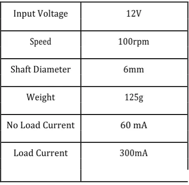
[image:5.595.315.557.56.177.2]These types of motors also have two different speed specifications: normal s peed and the stall -speed torque specifications.
Table 1. Specifications
Gear motors are primarily used to red uce speed in a series of gears, which in turn creates more torque. This is accomplished by an integrated series of gears or a gear box being attached to the main motor rotor and shaft via a second reduction shaft. The second shaft is then connected to the series of gears or gearbox to create what is known as a series of reduction gears. Generally speaking, the longer the train of reduction gears, the lower the output of the end, or final, gear will be.
2.1.8 Output section
The output section consist of a SP ST switch and a 3-pin socket wit h a specifications of 230v 50Hz . The leads from the capacitor banks are fitted into the switch and the socket via diodes. for the indication we use a LED Lamp of 230v 3w. Fitted into the socket with the help of an adapter holder.
As the output section is a box consisting of only switch and socket they are fitted into plywood via screws.
[image:5.595.38.232.260.449.2]Fig.7. Output
3. DESIGN REQUIREMENTS AND BASIC OPERATION
100 RPM helical Shaft 37mm Diameter Compact DC Gear Motor is suitable for t he purpose of rotation of flywheel via magnetic coupling. It has sturdy construction with gear box built to handle stall torque produced by the motor. The entire motor is Drive shaft is supported from both sides with metal bushes. Motor runs smoothly from 4V to 9V and gives 60 RPM at 9V. Motor has 6mm diameter, 22mm length drive shaft with D shape for excellent coupling.
Important Note: This motor will be bit noisy while running. For long life, this motor is not recommended for application requiring dynamic torque of more than 3 kg -cm.
Basic principle of operation include,
A gear motor can be either an AC (alternating current) or a DC (direct current) electric motor. Most gear motors have an output of between about 1,200 to 3,600 revolutions per minute (RPMs).
These types of motors also have two different speed specifications: normal speed and the stall -speed torque specifications.
Gear motors are primarily used to reduce speed in a series of gears, which in turn creates more torque. This is accomplished b y an integrated series of gears or a gear box being attached to the main motor rotor and shaft via a second reduction shaft. The second shaft is then connected to the series of gears or gearbox to create what is known as a series of reduction gears. Generally speaking, the longer the train of reduction gears, the lower the output of the end. Input Voltage 12V
Speed 100rpm
Shaft Diameter 6mm
Weight 125g
No Load Current 60 mA
© 2019, IRJET | Impact Factor value: 7.211 | ISO 9001:2008 Certified Journal | Page 3350
4. DESIGN AND WORKING 4.1 DESIGN
Fig.8. Circuit Diagram
The above figure shows the circuit diagram regarding this project
DC 6v is supplied to the helical g eared motor with the help of a ordinary (AC) switch for ON/OFF control of the motor.
The output from the synchronous motor is connected to the output box and also to the capacitor bank with the help of diodes.
The input of the capacitor bank consist of d iodes (1N4007) for the uni directional flow of stored energy.
The diode is used to prevent the back flow of generated voltage to the generator and the output from the capacitor banks is taken after the diode part to the output box
The output part consist s of a SPST switch (230v, 5A) and 3-pin socket
(230v, 5A), LED lamp (230v, 3w). The LED lamp is connected to the socket with the help of a bulb holder adapter.
Fig.9. Design 4.2 WORKING
Electrical energy is used to spin the flywheel at great speeds and to store energy. The greater the rotational speed of the flywheel, the greater the
amount of charge stored in it. Thus the energy is stored and it can be retrieved at a later point of time. The flywheel keeps spinning at a particular speed as long as ener gy is not retrieved from it. The speed at which the flywheel rotates is reduced when energy is retrieved from it. The flywheel stops spinning once all the energy is drained from the system.
In this project the flywheel is rotated using a helical geared mot or (100 rpm) with a brass coupler coupled to the motor shaft, at end of the brass coupler threaded rod of 4cm is fitted inside it, then two neodymium magnets of opposite polarity is placed to it with the help of better adhesives. Thus when the motor rota tes N-S poles interchange alternatively prov iding a rotating magnetic flux f or the flywheel to rotate. The geared motor works on 6 VDC and provides an rpm of 60, also a switch is provided for ON/OFF of the motor.
This project can be used only as a standby power, because it can provide power only for short intervals of time. As the fly wheel is rotated to a specified rpm it stores the rotational energy into the kinetic energy. The flywheel used here is of cast iron type and it weighs about 3kg and provides enough torque for the rotation of synchronous motor.
Here in this project there are Self -Discharge (spinning loss) results from a combination of mechanical ball bearing drag, windage, and electromagnetic drag torques. It is very challenging to disaggregate these losses from one another, as they occur simultaneously. However, electromagnetic drag torque in our design is essentially negligible, since it is pessimistically estimated to have a maximum value of 5 W (or about 1.6% of total self -Discharge loss) at peak speed. Windage and bearing losses are thus assumed to constitute the main components of spinning loss. Spinning loss can be easily measured with good accuracy by simply recording the rate of deceleration of the flywheel in an idle state, and calculat ing the corresponding power loss.
© 2019, IRJET | Impact Factor value: 7.211 | ISO 9001:2008 Certified Journal | Page 3351
rpm. The helical geared motor is switched OFF . thus due to the inertia of rotation; the stored kinetic energy makes the flywheel to rotate for a short period of time. During this time also the high torque synchronous motor rotates and produces 230vac. As when the speed of flywheel becomes slower and suddenly stops . During this time the capacitor bank provides the stored electrical energy to the output for a short period of time. Here in the output an LED lamp of 230v 50Hz, 3W is used to serve the purposes
4.3 MECHANICAL DESIGN
4.3.1 Wooden Base
Wooden base is made of super tough hardwood plywood, in order to carry heavy weights and vibrations. Hardwood plywood is made out of wood from angiosperm trees and used for demanding end uses. Hardwood ply wood is characterized by its excellent strength, stiffness and resistance to creep. It has a high planar shear strength and impact resistance, which make it especially suitable for heavy -duty floor and wall structures. Oriented plywood construction has a h igh wheel-carrying capacity. Hardwood plywood has excellent surface hardness, and damage - and wear-resistance. Such a wooden base as the ability to distribute the weights equally to the pro vided bushings for excellent stability. As the wood is prone to decaying black enamel paint is provided on the surface for long life. Plastic bushings are provided below the plywood on every corner for the equal distribution of weights and vibration to the ground.
For placing of different components on the surface of the plywood 8mm holes are made and suitable screws are provided to keep the components in required places and puttey’s are used for bonding the components and filling the unused holes.
Fig10. Wooden Base
4.3.2 Base Support
The base support, supports the entire vertical flywheel system and also makes it perfectly stable during the rotation of heavy duty flywheel.
[image:7.595.110.227.611.700.2]The base support is made from mild steel pipe with a diameter of 2cm, thicknes s of 1cm and height of 4cm. the ferrite magnet placed belo w the shaft goes into the base support and fits inside it tightly. F or the mild steel pipe drilled into the plywood iron L -clamps are used and welded to the surface of mild steel pipe. In order to prevents small accidents all the, sharp ends and sharp parts are grinded with the help of grinder.
Fig. 11. Base Suppourt
In order to prevent the parts from rusting metallic black paint is applied on the surface. With the help of suitable screws the bas e support is fitted on the surface of plywood.
4.3.3 Shaft Design
The shaft is made of cast iron and it is designed using the mechanical lathe. It’s having different dimensions on different parts as the shaft goes down the dimension decreases.
In order to couple the flywheel to the shaft, 2cm diameter is set on the shaft from 3cm from the top.
In order to couple it to the ball bearing 1.5cm diameter is set on the shaft from 9cm from top.
4.3.4 U-Shaped Stand
In order to place the synchronous motor in specified place a U-shaped stand is made. T he u shaped stand is made of hardened steel, actually the stand is shaped in the form of pulse wave, therefore the stand can be fitted on to the plywood using suitable screws.
On the top part the synchronous moto r is placed by providing two holes alternative to each other and the motor is held in the middle with the help of long screws.
© 2019, IRJET | Impact Factor value: 7.211 | ISO 9001:2008 Certified Journal | Page 3352
Fig. 12.U shaped Stand
5. IMPLEMENTATION
Grid Impacts an d Benefits, This section describes the projected impacts and benefits of the flywheel energy storage technology on the electric grid. For an example 1 MW 4 MWh flywheel energy storage installation based in Northern California, with operational results extrapolated from such a system initial field demonstrations of the Gen-2 flywheel technology, we expect the following impacts & benefits to accrue: Project Size: 1 MW 4 MWh Greenhouse Gas Emissions: Based on our assumption that 1 MW of energy storage would e nable an additional 5 MW of renewable generation (with 25% annual capacity factor assumed), storage would enable an additional 10,950 MWh of energy delivered annually from renewables. The calculated greenhouse gas emissions saved would be 3,098 metric tons saved per year (0.283 metric tons / MWh from fossil generation). Additionally, because the flywheel energy storage system is designed to provide multiple grid services: ancillary services, load ramping & peak shaving, our expectation is that the flywheel system will be dispatched on average 8000 hours per year, or at a 91.3% capacity factor.
Thus, by employing flywheel energy storage instead of traditional fossil generation, assuming the same (0.283 metric tons of CO2 / MWh from fossil generation), employ ing flywheel energy storage would save an additional 2264 metric tons of CO2 per year. Compared to an energy storage system that is designed primarily for peak shaving, where annual capacity factors may be 5% or 438 hours per year, the CO2 savings in that case would only be 124 metric tons per year. Thus, we see that the most impactful energy storage solution is one that can be utilized at high capacity factors over decades, enabling higher renewable penetration while also supplanting fossil generation for providing ancillary and ramping services. Water Savings: While it is difficult to estimate the water use of newer generations of fossil fuel power plants, Amber’s flywheel technology employs NO water –
the entire system is passively cooled and thus provides a net water savings.
6. CONCLUSION AND FUTURE SCOPE
6.1 CONCLUSIONS
This report discusses the objectives and demonstration results flywheel energy generation using magnetic repulsion. This is a low-cost flywheel energy storage demonstration project. The scope of this report covers the project’s initial goals, of ene rgy production. In this project, we have successfully demonstrated a prototype for magnetic repulsion flywheel energy storage system. Our demonstrations confirmed that this project can produ ce 230v for a short period of time and can be used as stand - by power for short period of time. our flywheel system met major design specifications, and we have converged on an effective set of operational and cost targets for the flywheel system. The product is now under goes different developmental ideas to increase the efficiency of generation at much more extend.
Based on the technology demonstrated in this project, we believe that flywheels will be an important energy storage technology for several energy storage applications, primarily where high utilization rates are demanded. Future programs designed to demonstrate our the flywheel systems would be beneficial in showcasing the potential for flywheels to emerge as a viable alternative to chemical ba tteries for multi-hour storage applications
6.2 FUTURE SCOPE
The flywheel energy using magnetic repulsion, produces energy without any harm to the environment and also it does not any type of green house gasses, thus such an energy generation system is eco friendly , the parts which used can be 100% recyclable.
As the common type of energy systems produce green houses gases and cause harm to the environment therefore the large scale flywheel energy systems can be a substitute for these generators with same configurations.
The prototype made in this project can be used as a substitute for batteries because it can store energy for a short period of time. but compared to battery the production s clean and eco friendly.
© 2019, IRJET | Impact Factor value: 7.211 | ISO 9001:2008 Certified Journal | Page 3353
treated properly due to the harmful contents used in it (mercury, cadmium etc...)
Thus in future our project has a great scope in the energy generation fields and also for green and cheap energy reso urces. This type of flywheel energy generation systems can be used in remote places like island nations and micro grids, the requirement for reliability, and sustainability makes multi-hour flywheel storage systems attractive as a replacement to traditiona l grid power. i.e. (large scale flywheel energy generation).
REFERENCES
[1] https://journal.esrgroups.org/jes/papers/4_2_10. [2] https://en.wikipedia.org/wiki/Flywheel_energy_sto
rage
[3] www.ece.uidaho.edu/hydrofly/Flywheel/.../Refere
nces/%5B3%5D/Satish%20Thesis
[4]
https://uu.diva-portal.org/smash/get/diva2:476114/FULLTEXT01
[5] https://www.researchgate.net/profile/Salima_Nem
si3/publication/312230643_Role_of_Flywheel_Ener gy_Storage_System_in_Microgrid/links/587796950 8ae8fce492fc392/Role-of-Flywheel-Energy-Storage-System-in-Microgrid.pdf
[6] https://journal.esrgroups.org/jes/papers/4_2_10 [7]
http://iopscience.iop.org/article/10.1088/1757-899X/21/1/012012
[8] https://ieeexplore.ieee.org/document/6401816/ [9] http://amberkinetics.com/
[10]https://www.smartgrid.gov/project/amber_kinetic
s_inc_flywheel_energy_storage_demonstration.html
[11]