ISSN Online: 2161-4873 ISSN Print: 2161-4865
Modelling and Simulation of Solidification
Phenomena during Additive Manufacturing of
Bulk Metallic Glass Matrix Composites
(BMGMC)—A Brief Review and Introduction of
Technique
Muhammad Musaddique Ali Rafique
School of Engineering (Aerospace, Mechanical and Manufacturing), RMIT University, City Campus, Melbourne, Australia
Abstract
Despite a wealth of experimental studies focused on determining and im-proving mechanical properties and development of fundamental understand-ing of underlyunderstand-ing mechanisms behind nucleation and growth of ductile phase precipitates from melt in glassy matrix, still, there is dearth of knowledge about how these ductile phases nucleate during solidification. Various efforts have been made to address this problem such as experiments in microgravity, high resolution electron microscopy and observation in synchrotron light af-ter levitation but none have proved out to be satisfactory. In this study, an ef-fort has been made to address this problem by modelling and simulation. Current state of the art of development, manufacturing, characterisation and modelling and simulation of bulk metallic glass matrix composites is de-scribed in detail. Evolution of microstructure in bulk metallic glass matrix composites during solidification in additive manufacturing has been pre-sented with the aim to address fundamental problem of evolution of solidifi-cation microstructure as a result of solute partitioning, diffusion and capillary action. An overview is also presented to explain the relation of microstructure evolution to hardness and fracture toughness. This is aimed at overcoming fundamental problem of lack of ductility and toughness in this diverse class of materials. Quantitative prediction of solidification microstructure is done with the help of advanced part scale modelling and simulation techniques. It has been systematically proposed that 2-dimensional cellular automaton (CA) method combined with finite element (for thermal modelling) tools (CA-FE) programmed on FORTRAN and parallel simulated on ABAQUS would best How to cite this paper: Rafique, M.M.A.
(2018) Modelling and Simulation of Solidi-fication Phenomena during Additive Manu-facturing of Bulk Metallic Glass Matrix Composites (BMGMC)—A Brief Review and Introduction of Technique. Journal of Encapsulation and Adsorption Sciences, 8, 67-116.
https://doi.org/10.4236/jeas.2018.82005
Received: February 6, 2018 Accepted: June 22, 2018 Published: June 25, 2018
Copyright © 2018 by author and Scientific Research Publishing Inc. This work is licensed under the Creative Commons Attribution International License (CC BY 4.0).
http://creativecommons.org/licenses/by/4.0/
Open Access
be able to describe this complicated multiphysics phenomenon in most effi-cient way. Focus is laid on quantification of methodology by which modelling and simulation can be adopted and applied to describe evolution of micro-structure in this important class of materials. It is found that proposed meth-odology is meritorious.
Keywords
Solidification, Modelling and Simulation, Cellular Automaton
1. Introduction
Discovered in 1960 by Duwartz etal.[1] at Caltech, Metallic Glasses [2] may be defined as disordered atomic-scale structural arrangement of atoms formed as a result of rapid cooling of complex alloy systems directly from their melt state to below room temperature with a large undercooling and a suppressed kinetics in such a way that the supercooled state is retained/frozen [3] [4] [5] [6]. This re-sults in the formation of “glassy structure”. The process is very much similar to inorganic/oxide glass formation in which large oxide molecules (sili-cates/borides/aluminates/and sulphides) form a regular network retained in its frozen/supercooled liquid state [7]. The only difference is that metallic glasses are comprised of metallic atoms rather than inorganic metallic compounds. Their atomic arrangement is based on mismatch of atomic size and quantity (minimally three) [8], is based on short [9] [10] [11] to medium range order [12] [13] [14] or long range disorder [15] (unlike metals—well defined long range order) and can be explained by other advanced theories or mechanisms such as liquid-liquid transition [16] [17] [18], phase separation [19], confusion [20], or-der in disoror-der [13] [21] [22] [23] [24], frustration [21], and vitrification [25] [26]. Important features characterizing them are their amorphous microstruc-ture and unique mechanical properties. Owing to absence of mechanisms pro-moting development and movement of dislocations, no plasticity is exhibited by bulk metallic glass matrix composites. This results in very high yield strength and elastic strain limit as there is no easy plane of flow. From fundamental defi-nition standpoint, metallic glasses are typically different from bulk metallic glasses, in that the former is glassy structure less than 1 mm thick, while later is greater than 1 mm [27] [28]. Till date, the largest bulk metallic glass produced in “as cast” condition is 80 mm diameter and 85 mm in length [29]. There are re-ports of making large thin castings as casing of smart phones but they are typi-cally less than 1 mm [30]. Furthermore, they are characterised by special proper-ties such as glass forming ability (GFA), and metastability.
2. Formation and Stability—Three Laws
The formation and stability of bulk metallic glasses is described by their ability
to retain glassy state at room temperature. In initial days of metallic glass and bulk metallic glass development, it was very difficult to retain glassy structure at room temperature. Only alloys falling into window of very narrow composi-tional contrast cooled at extremely high cooling rate can form glassy structure [1] [2] [27] [31] [32]. A deviation from any of these parameters severely ham-pers their glassy state and crystallisation occurs [33] [34] [35]. This property is known as glass forming ability (GFA) [36]. This is single most important prop-erty in metallic glass family of alloys which governs their formation and evolu-tion. GFA has been increasingly studied and considerable progress has been made in its improvement [37] [38] [39] [40] by alterations and improvement in both composition and processing condition’s window [15] [41] [42]. Now, alloys having multicomponent composition can be cast in glassy state even at slow cool-ing rates owcool-ing to their superior glass formcool-ing ability [38] [43]-[48] which in turn is governed by various theories [40] [43] [49]-[60] and analytical models [61] [62].
Fundamentally, research over the period of time has yielded three basic laws which are now considered universal for forming any bulk metallic glass system [8]. These are described as follows. Any glass forming system consist of elements which must:
1) Be three in number (at minimum). (Elements greater than 3 are considered beneficial).
2) Differ in their atomic size by 12% among three elements. (Atoms of ele-ments with large size are considered to exhibit superior glass forming ability).
3) Have negative heat of mixing among three elements. (This ensures ten-dency to demix or confuse [20] ensuring retention of glassy structure at room temperature).
This result in new structure with high degree of densely packed atomic con-figurations, which in turn, results in completely new atomic configuration at lo-cal level with long range homogeneity and attractive interaction. In general bulk metallic glasses or bulk glassy alloys are typically designed around alloy systems that exhibit: 1) a deep eutectic, which decreases the amount of undercooling needed to vitrify the liquid, and 2) alloys that exhibit a large atomic size mis-match, which creates lattice stresses that frustrate crystallisation [8]. An impor-tant way to arrive at optimum glass forming composition and then selecting al-loying elements is based on proper choice of eutectic or off-eutectic composi-tion, diameter and heat of mixing [15]. These laws were first proposed by Ab-dullah S. Jabri and Douglas C. Hoffmann at Jet Propulsion Laboratory, Caltech [8] and Prof. Akisha Inoue at WPI-IMR, Tohoku University, Japan [15] inde-pendently.
3. Ductile Bulk Metallic Glass and Bulk Metallic Glass Matrix
Composites
Inherent brittleness, which is a big disadvantage in manufacturing and applica-tion of bulk metallic glasses at large scale can be overpowered by inducing
ticity in glassy structure while retaining its high strength at the same time [63] [64] [65] [66]. This can be done by various mechanisms including exploitation of intrinsic ability of glass to exhibit plasticity at very small (nano) length scale [67] [68], introduction of external impulse (obstacles) to shear band formation and propagation (ex-situ composites) [69] [70], self or externally assisted multi-plication of shear bands [71] [72], formation of ductile phases in brittle glassy matrix during solidification (in-situ composites) [73] [74] [75] [76] and trans-formation inside a ductile crystalline phase e.g. B2 - B19’ transtrans-formation in Zr based systems (stress/transformation induced plasticity (TRIP) [77] [78] [79] [80]. It was known thermodynamically and observed after simulation [81] and experimentation [82] [83] [84] [85] since early days that structurally constrained glass either relaxes (losses free volume) or underwent crystal structure change (devitrification) during heating. The drive for devitrification [86] [87] did not came out of ingenious effort but was an outcome of natural impulse of stressed structure to attain a state of lower stress by undergoing structural change and evolution of new structures (phases) when subjected to temperature effect simi-lar to heat treatment for crystalline metallic alloys. This result in new class of bulk metallic glass called ductile bulk metallic glass [88]-[96]. Other approach which encompasses nucleation and growth of primary ductile phase in brittle glassy matrix during solidification gave rise to second type of ductile material known as ductile bulk metallic glass matrix composites. These were reported first time in 2001 by Prof. William L. Johnson’s group at Caltech [63] when they successfully incorporated primary ductile phase reinforcements in glassy matrix in the form of precipitates in-situ nucleating during solidification thus giving birth to “so called” family of in-situ dendrite/metallic glass matrix composites [97]-[112] Later reinforcements were observed to exhibit different morphologies other than dendrites (e.g. spheroid, whiskers and plates) but fundamental mechanism of reinforcements remained same (i.e. metal matrix composites). These materials are formed as a result of conventional solute partitioning mechanisms as observed in other metallurgical alloys resulting in copious for-mation of ductile phase (Ti-Zr-Nb β in case of Ti based composites [63], B2 CuZr in case of Zr based composites [113]-[118] or transformed B2 (B19’ mart-ensite) in case of shape memory alloys (a special class of bulk metallic glass ma-trix composites) [73] [116] [119] [120] [121] [122] [123]). This ductile phase can appear in the form of three dimensional dendrites or spheroids emerging di-rectly from liquid during solidification. Structural changes in these alloys can be explained by “phase separation” [124]-[131] before liquid-solid or solid-solid transformation or formation and retention of “quenched in” nuclei during so-lidification. This is another very important route for the manufacture of these alloys. Very recently, another important phenomenon known as liquid-liquid transition (LLT) [17] has been observed in these alloys. This has become ob-servable due to ability to characterize these alloys under Synchrotron radiation [132] [133] [134] [135] and in microgravity conditions [17] [136] employing container less levitation techniques [136].
These impart their special properties (enhanced plasticity and compressive strength) not otherwise attainable by conventional processing routes or in sim-ple binary and ternary compositions. This however, is seldom the case and is not readily observed as compared to solid state phase separation [124] which is dominant mechanism in these alloys. More advanced mechanisms of forming these materials are by local microstructural evolution by phase separation right at shear bands [38]. It narrates that solid-solid phase separation (spinodal de-composition) occurs at the onset of shear band which is the cause of micro-structural evolution. Few notable class of alloys in these types of ductile compos-ites are Ti based BMGMCs [137]-[144], Ti based shape memory BMGMC [145], Zr-Cu-Al-Ti [146] [147], Zr-Cu-Al-Ni [148], and Zr-Cu-Al-Co shape memory BMG composites [149]. Each has its own mechanisms of formation and indi-vidual phases are formed by liquid-solid or solid-solid phase transformations.
4. Additive Manufacturing of Bulk Metallic Glasses and their
Composites
Although, considerable progress has been made in advancing “as cast” sizes in bulk metallic glass and their composites, still, maximum possible diameter and length which has been produced by conventional means till date [29], is far from limit of satisfaction to be used in any structural engineering application. This primarily is associated with mechanical cooling rate achievable as a result of quenching effect from water cooled walls of Cu container which in itself in not enough to overcome critical cooling rate (Rc) of alloy (~0.067 K/s [29]) to pro-duce a uniform large bulk glassy structure. In addition to this, occurrence of this bulk glassy structure is limited to compositions with excellent inherent glass forming ability (GFA) [150] [151]. This is not observed in compositions which are strong candidates to be exploited for making large scale industrial structural components [48] [78] [142] [144] [148] [149] [152] [153] [154] [155] with higher critical cooling rates (Rc) (10 K/s [48]). This poses a limitation to this conventional technique and urges the need of advanced manufacturing method which does not encompass these shortcomings.
Additive Manufacturing has emerged as potential technique [156] [157] to fulfil this gap and produce bulk metallic glass matrix composites [158] [159] in single step across a range of compositions virtually covering all spectrums [160] [161] [162] [163]. It achieves this by exploiting very high cooling rates available in very short period transient liquid melt pool [164] [165] [166] in a small region where laser strikes the sample (LSM/LSF (solid), SLM/LENS (powder)). This,
when coupled with superior glass forming ability (GFA) of bulk metallic glass matrix composites (BMGMC), efficiently overcome dimensional limitation as virtually any part carrying glassy structure can be fabricated. In addition, in-cipient pool formation [166] and its rapid cooling results in extremely versatile and beneficial properties in final fabricated part such as high strength, hardness, toughness, controlled microstructure, dimensional accuracy, consolidation and
integrity. The mechanism underlying this is layer-by-layer (LBL) formation, which ensures glass formation in each layer during solidification before pro-ceeding to next layer. That’s how; a large monolithic glassy structure can be produced. This layer-by-layer (LBL) formation also helps in development of secondary phases in a multicomponent alloy [167] [168] [169] as layer preceding fusion layer (which is solidified) undergoes another heating cycle (heat treat-ment) below melting temperature (Tm) somewhat in the nose region of TTT diagram [158] which not only assist in phase transformation [109] [111] but also helps in increase of toughness, homogenisation and compaction of part. This is a new, promising and growing technique of rapidly forming metal [170], plastic [171], ceramic or composite [172] parts by fabricating a near-net shape out of raw materials either by powder method or wire method (classified on the basis of additives used). The movement of energy source (laser or electron beam) is dictated by a CAD geometry which is fed to a computer at the back end and manoeuvred by CNC [173] [174] system. Process has wide range of applicability across various industrial sectors ranging from welding [175]-[180], repair [181] [182], and cladding [183]-[189] to full scale part development.
However, there is dearth of knowledge about exact mechanisms of formation (nucleation and growth and/or liquid-liquid transition [16] [17] [18]) of ductile phase dendrites in-situ during solidification of BMGMC happening inside liquid melt pool of additive manufacturing which is essential to further advance im-provement in the process and suggest its optimisation. Modelling and simula-tion techniques especially those employing finite element methods (FEM) (phase field [190]-[195]), and CAFE [196]-[201]) at part scale are very helpful in ex-plaining the evolution of microstructure and grain size development in metals and alloys. They have been extensively used in predicting solidification behav-iour of various types of melts during conventional production methods [201] [202] [203] [204]. However, their use in additive manufacturing applications [205] [206] [207] [208] specially related to BMGMC is still in its infancy. Virtu-ally no effort has been made to understand nucleation and growth of ductile phase crystalline dendrites in-situ during solidification in BMGMC by modelling and simulation. A step forward is taken in present study to address these gaps and bring together the strengths of different techniques and methodologies at one platform. A comprehensive review of existing literature is presented and a tale of manufacturing of these alloys is described with step-by-step arrival at set of equations which are proposition of solution methodology. Ductile bulk metal-lic glass metal matrix composites are proposed to be formed by taking advantage of
1) Materials chemistry: A multicomponent alloy. Its glass forming ability (GFA) is used as a measure to manipulate composition and vice-versa.
2) Solidification processing: Liquid melt pool formation, its size, shape and geometry, role of number density, size and distribution of ductile phase in resul-tant glassy alloy matrix. It is taken as a function of type, size and amount of
cleates (inoculant).
3) Additive manufacturing: Use of very high cooling rate inherently available in the process to (a) not only form glassy matrix but use liquid melt pool formed at very high temperature to trigger nucleation (liquid-solid transformation) of ductile phase in the form of dendrites from within the pool “in-situ” (This is done by controlling machine parameters in such a way that optimised cooling rate satisfying narrow window of “quenching” bulk metallic glasses is achieved) (b) take advantage of heating (heat treatment) of preceding layer to trigger solid-solid transformation (devitrification) again to form ductile phase and achieve homogeneity, consolidation and part integrity eliminating the need of post processing or after treatment and
4) Modelling and Simulation: Strong and powerful mathematical modelling techniques based on
a) Transient heat transfer for “liquid melt pool formation as a result of la-ser-matter interaction” and
b) Its “evolution-solidification” by
i) Deterministic (modified classical nucleation theory, JMAK Correction and Rappaz Modification) or
ii) Stochastic/probabilistic (3D CAFE model for nucleation and growth (solute diffusion and capillary action driven))
Modelling of microstructure evolution comprising of ductile phase (in some case equiaxed dendrites) evolution in glassy melt will be used to simulate the conditions in liquid melt pool of BMGMC during additive manufacturing. It is envisaged that effect of number density, size and distribution of ductile phase dendrites will be evaluated/verified by simulation of melt pool developed using different values of aforementioned parameters.
Note: Additive Manufacturing (AM) methods can also be classified on the ba-sis of energy source used (i.e. Laser based or Electron Beam based).
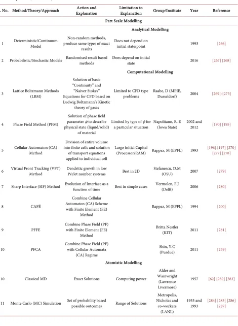
5. A Brief Introduction to Modelling and Simulation
Although, in use since ancient Roman times [209], modelling and simulation picked up interest and achieved pinnacle in modern day scientific and engineer-ing sectors with the advent of computer technology which came not more than two decades ago. Now, it has proved itself to be important integral part of prod-uct and part design, prodprod-uct development as well as prediction, utilisation and enhancement of properties. Various branches of modelling and simulation, ranging from part scale modelling which involves development of codes of theorems in advanced computing platform such as FORTRAN, Java, C++,
MATLAB and Python to their stand alone or parallel simulations in
custom-ised simulation languages/packages such as ABAQUS, Solidworks, Ansys
and Catia to performing complex atomistic simulations in dedicated
proprie-tary software, have now become integral part of design procedure in major in-dustrial clusters. Its use in research and development is also becoming an
portant part of whole process to eliminate so called “trial and error” methods which are not only time consuming but are energy, materials and resources ex-tensive. In materials science and engineering mainly two of its branches are rou-tinely used. These are “part scale modelling and simulation” and “atomistic modelling and simulation”. The former is used for the complete design of com-plex machinery segments, equipment, assemblies, sub-assemblies, their materials of fabrication and property prediction in different regions as a function of ex-trinsic parameters such as heat, velocity, pressure, time whilst the latter is used for the prediction, estimation and improvement in atomic-scale properties using theories of atomic configuration and arrangement mainly relying on intrinsic parameters (such as specific heat/latent heat, heat capacity, density, heat of fu-sion and atomic fit or misfit). The unique ability of atomistic modelling and simulation is that it uses atomic functions and their variables to generate knowledge about their behaviour under various impulses. In both cases, the use of these methods are big help and support in saving time, materials, resources as well as improve functionality and in-service property development and behav-iour prediction.
The exponential rise in the use of modelling and simulation with the advent and progress of computer technology and increase of computing power of ma-chines gave rise to greater flexibility in the design and development process. Many difficult, or in some cases, impossible to envisage problems can now be simulated using these computing platforms. These include simulation of water flow and its patterns in rivers and channels, simulation of interior of sun, stars and other heavenly bodies, cosmic events and nuclear engineering problems. However, despite of these advantages, there are still situations and applications which limits the use of modelling and simulation techniques. These include, un-availability of strong efficient computing algorithms (with lesser approxima-tions) needed for the replication of actual real-world situations, unavailability of real world experimental data (physical constants and thermo-physical proper-ties) needed to simulate a particular problem, unavailability of more accurate deterministic or accurate (non-probabilistic) models using actual situations rather than basing their outcome on statistics. Owing to these reasons, there is still need for further investigation and removal of bottlenecks from modelling and simulation techniques and it is envisaged that their popularity is still at arm’s length. However, progress in these is notable and healthy.
6. Current State of art in Modelling and Simulation of
Additive Manufacturing of Bulk Metallic Glass and their
Composites
Nucleation and growth phenomena in single component (pure metals), binary and multicomponent alloys is rather well understood. Classical nucleation the-ory (CNT) [210] provides many answers to the behaviour of these melts. Tradi-tionally, bulk metallic glass and their composites were produced using
tional methods (Cu mould suction casting [211] [212] [213] and twin roll casting [214]) in which their metastable phase (glass) and any in-situ ductile precipitates (stable phase) are nucleated based on their ability to surpass activation energy barrier. In addition, these processes, impart very high cooling rate to castings which is essential for retention of supercooled liquid (glass) at room tempera-ture. However, they have their limitations which pose limits to their applicability and use for making complex and intricate parts and components at large scale.
Very recently, with the advent and popularity of additive manufacturing (AM), interest has sparked to exploit the inherent and fundamental advantages present in this unique process to produce BMG and BMGMCs. Additive manu-facturing techniques are useful in achieving this objective as very high cooling rate in fused liquid melt pool is already present inherently to assist the formation of glassy structure which is suppression of “kinetics” and prolonging of under-cooling (“thermodynamics”)—two main phenomena responsible for any phase transformation. However, the in-situ nucleation of primary phase equiaxed dendrites or spheroids during solidification and then microstructural evolution (solutediffusion and capillaryaction assisted) is not satisfactorily explained by classical nucleation theory alone.
Either some modification is needed in classical nucleation theory (CNT) or more reliable probabilistic microstructure evolution models (e.g. J-M-A-K Cor-rection [215] or Rappaz modification) are needed to explain nucleation and growth (and other phenomena e-g liquid-liquid transition (LLT) [17] [18] [19] and phase separations [128]) in BMGMCs. In this work, an effort has been made to meet both requirements. Following are propositions and state of art;
1) At present scenario, there is no single hybrid/combined model which ex-plain phenomena of heat transfer (liquid melt pool formation as a result of la-ser-matter interaction and its evolution-solidification) and coupled this with nu-cleation and growth (NG) (solute diffusion [216] and capillary action driven) at microscale to predict microstructure and grain size in BMGMC as melt cools in additive manufacturing melt pool.
a) Only one study has been conducted to model the same phenomena (solidi-fication only) during Cu mold suction casting which will serve as base [217] in addition to very recent attempts [215] in which emphasis is laid on development of generalised theory rather than solving a problem.
b) Only one study has been reported on microstructure formation during twin roll casting using cellular automaton-finite element (CAFÉ) [218] but that is not aimed at BMGMCs, is carried out using commercial software package and does not involve any mathematical modelling at the back end. Software embedded (nucleation and growth and heat transfer) models are used only.
c) Four prominent studies namely by Zhou etal.[207], Zhang etal. [208], Zi-noviev et al. [205] and a group at Shenyang, China [80] [206], have been re-ported very recently using CAFE but these are based on modelling microstruc-ture evolution in modified additive manufacturing (HDMR [207], LAMP [174]
on 316L SS [208], 2D CAFE [205], Cladding [80] [206]) processes.
d) Few studies in the past have been conducted employing selective laser melting (SLM) using CAFE [80] [206] [219] [220], CAPF, CAFVM [221], modi-fied CAFE [222] approaches but none have been carried out on BMGMC.
2) No effort has been made to correlate the effect of edge-to-edge matching (E2EM) [223] [224] with direction of easy heat flow and crystallographic orien-tation (an effect that can be inherently used in additive manufacturing).
3) No substantial study has been reported about evolution of microstructure in three dimensions in BMGMCs in additive manufacturing.
4) No effort has been made to combine the effect of changing properties with decrease of temperature (transient conditions). Most of models till now predict solutions in terms of steady state phenomena.
5) Very few studies have been carried out to combine cellular automaton (CA) with finite element (FE) in case of additive manufacturing (AM) while it is rou-tine approach to predict grain size in case of other processes (casting, welding).
In light of this research gap, present review is compiled. An effort has been put together to overcome these shortcomings and propose a methodology for the modelling and simulation of solidification phenomena during additive manufacturing of BMGMCs. A model system Zr47.5Cu45.5Al5Co2 has been pro-posed owing to evolution of distinct ductile phase (CuZr-B2) in it during solidi-fication and its tendency to show shape memory effect (exhibiting two types of martensitic phase evolution from B2 phase). Further, the method is proposed to be applied to conventional wedge shape casting geometry along with its final ap-plication to melt pool in additive manufacturing making use of powers of de-terministic, probabilistic and their coupled modelling approaches. This route is proposed to get maximum benefit from application of modelling and simulation to understand nucleation and growth phenomena during solidification both in conventional as well as modern processing technologies (AM). It is envisaged that application of hybrid CAFE model by programming on FORTRAN/MATLAB and parallel simulation on ABAQUS will help
under-stand solidification in BMGMC in much better way not done elsewhere previ-ously.
7. Modelling—Introduction
This analysis is divided into two sections. The first section deals with the evolu-tion of the melt pool as a result of the interacevolu-tion of highly localised, focused la-ser light with matter (metal powder). This results in the formation of a melt pool whose shape, size, geometry and transient behaviour is very much a function of the heat transfer coefficients (HTC) evolving at every step of its formation (melting and homogenisation) and dissipation (solidification). Solidification in this section is considered by a modified general (classical) nucleation theory (CNT) [225]. Once formed, this pool travels as the laser traverses its path all along the powder bed dictated by CAD geometry at the back end. The second
section deals with the microstructural evolution during solidification which is primarily a solutediffusion and capillaryaction dominated phenomena. This is dealt with by microscopic 2D and 3D probabilistic cellular automaton models which model nucleation and equiaxed dendritic growth resulting in the forma-tion of the microstructure within the liquid melt pool as it solidifies. Advantages and disadvantages of cellular automaton method are also described. (Note: only “Vitrification (glass formation)” effects are considered and devitrification (glass to crystal precipitation) is not considered). The evolution of microstructure is checked against the variation of number density (nucleation density), volume fraction, size and distribution of ductile phase in the glassy matrix. Inoculants for ductile phase formation were selected previously by edge to edge matching (E2EM) [223] [224].
8. Modelling and Simulation of Heat Transfer in Liquid Melt
Pool-Solidification
As the microstructure formed during selective laser melting (SLM) is mostly co-lumnar [226], it is a good indicator that heat flux transfer from melt is highly unidirectional thus heat transfer from bottom is a transient 1D process. Al-though, heat is lost from the material in x-y plane i.e. perpendicular to the z-direction (perpendicular to build direction), its contribution is so low that it can be safely ignored. However, this was an old concept. New experimental ob-servations have proposed a new concept according to which during SLM, a melt pool is formed, where the shape of this pool is a function of;
1) Laser power (laser beam intensity).
2) Presence of thermocapillary convection (marangoni convection).
In even more advanced and recent models, [227] [228] the transfer of heat af-ter its generation is considered by three main parameaf-ters:
1) Heat transfer due to convection.
2) Evaporation (i.e. formation of plasma) (this results in re-radiation (inverse radiation)).
3) Conduction from the bottom and the side walls.
This is very recent and advanced approach which, however, ignores maran-goni convection effects. Overall, the heat transfer phenomena associated with the solidification of metal in a liquid melt pool in AM is associated with three proc-esses:
1) Generation of heat (laser matter interaction).
2) Assimilation of heat (melting and stages of solidification). 3) Extraction of heat.
8.1. Generation of Heat (Laser-Matter Interaction)
This is the first stage of additive manufacturing in which heat is generated. The problem in this stage is related with impingement of light of certain intensity (I) on a solid surface for a certain amount of time which may results in production
of heat. This interaction can be explained in terms of law known as the “Beer lambert law”.
Beer Lambert Law for Additive Manufacturing
Consider a thin layer of powder with thickness d1, on a flat disk substrate of re-fractory metal with thickness d2 and radius r uniformly illuminated by light of intensity I.
For absorptivity of powder (or melt) assuming uniform temperature throughout the disk, the temperature evolution is
(
ρ
1 1 1c d +ρ
2 2 2c d)
ddTt =A T I Q T( )
−( )
(1)where A(T) = Absorptivity; Q(T) = Thermal loss (convective and radiative); I = Intensity; ρ1 = Density of powder; ρ2 = Density of substrate; c1 = Specific heat of powder; c2 = Specific heat of substrate; d1 = Thickness of powder; d2 = Thickness of substrate.
Heat generated by this process is used for melt pool generation (its morphol-ogy, homogenisation, and holding (generation of supercooled liquid (SCL) re-gion and its progression)).
8.2. Assimilation of Heat (Melting and Stages of Solidification)
As the heat generated above interacts with metal powder, it causes its melting and generation of liquid melt pool. The behaviour of a certain metal/alloy in the melt pool can be explained by its cooling curve which is briefly described below.
8.2.1. General form of Cooling Curve
A cooling curve of a metal/alloy is a plot of the variation of temperature with time. It has different regions which embodied various types of information. Cooling curves can have different shapes depending on the metal or alloy type. A schematic cooling curve is shown in Figure 1 for a single component pure metal (without any inoculants).
Its distinct regions are explained as follows;
Region above A1: This is the region in which metal is in its complete liq-uid-state and can be described by only melting and liqliq-uid-state homogenisation. Heat carried by metal in this region is “super heat” only and lost in the form of specific heat (mcpΔT). This homogenisation in turn depends on type of melting (gas/solid (coal)/liquid (oil) fired crucible furnace melting, electric (resis-tance/induction/arc) melting) and subsequent melt treatment. (Note: Homog-enisation is required by some external means in case of all modes of melting. Only induction furnace is manifested by self-homogenisation due to phenomena of induction currents).
Region A1 - A: This is a region which is characterised by the loss of super heat until the first arrest point A. (Point at which the first nucleas form—explained in detail in later sections). This is also called the start of solidification. In pure met-als it is a sharp point (melting point) while in alloys, it can be a range
Figure 1. Cooling curve for a single component pure metal (without any inoculants).
(melting range). In BMGMCs/multicomponent alloys, it is also called start of the super cooled region (SCL). This region is followed by undercooling (ΔTn) region which is described below
Region A - D: This is the most important region of cooling curve (present case) for pure metals. In this region, metal cools down to a specific temperature characterised by a certain minimum amount of energy (activation energy for nucleation) needed to overcome a barrier of energy (energy barrier to nuclea-tion) to create a liquid-solid (L-S) interface eventually leading to formation of a stable nuclei out of the melt. This region is further divided into two regions A - C and C - D.
Region A - C: This is region in which undercooling occurs, heat is extracted, the temperature drops and shape of cooling curve goes down. This is character-ised by two energies described in the above paragraph.
Region C - D: This is the region in which heat energy is absorbed, temperature is gained and shape of curve goes up. This is called recalescence.
Notes:
1) Recalescence is gain in temperature as a result of thermal fluctuations caused by phase transformations occurring within solidifying melt/alloy. In pre-sent case, phase change is solid formation within undercooled liquid while thermal fluctuations are described by release of heat in the form of heat of fu-sion.
2) Region A - C is characterised by another point. Point “B” occurring in the
middle of cooling curve. This is specifically shown in Figure 1 as intermediate point of Supercooled liquid region (SCL). For the present case model (transient heat transfer conditions will be modelled at this point as well to get better un-derstanding of phenomena occurring in SCL in BMGMCs).
Region D - E: This is the region at which (after arrest point D), metal losses all its heat of fusion (mHf). In this region transformation occurs at constant tem-perature in such a way that all liquid gets transformed into complete solid (all fine equiaxed grains formation at mould wall (Cu mould casting)/at surface of inoculant (heterogeneous nucleation, not present case), “equiaxed-columnar” transition, growth of columnar dendrites, CET and growth of all equiaxed den-drites accomplishes). This is also called the solidification time.
Region E - F: This is the region in which solid cools. That is, after all liquid gets transformed into solid, the solid casting cools down to room temperature. This again occurs after a sharp invariant point (point F) in case of pure metals and after a range in case of multicomponent alloys.
8.2.2. Cooling Curve for Well Inoculated Zr-Based in-situ Dendrite BMGMCs
Shape of cooling curve changes its form as melt is changed from single compo-nent to binary to multicompocompo-nent alloys. This can be explained in the form of various cases.
Case 1: Well inoculated single component melt:
In these types of alloys, undercooling/undercooled region (ΔTn) diminishes and is almost absent. Inoculation with potent nuclei serves as active nucleation sites and triggers heterogeneous nucleation as the alloy reaches its first invariant point. Thus, no undercooling happens, and solid alloy directly starts cooling as all liquid gets transformed to solid at constant temperature.
Case II: Binary alloys without inoculants (slowly cooled) In these types of alloys cooling occurs in following steps
1) Distinct undercooling occurs (characterised by drop and gain (recales-cence) of temperature)
2) It is followed by region of constant temperature cooling which is called lo-cal solidification. This is only visible in case of very fluid alloys in which mushy region is very fluid/less viscous (not BMGMCs). This region is absent in most multicomponent (industrial) alloys as their solidification is dominated by mushy zone. (Note: BMGMCs are special case of alloys in which mushy region is exten-sively dominated but another phenomenon known as “sluggishness” governs the solidification. In these alloys, three laws [8] which describe BMGMC formation and evolution make sure that not only sluggishness dominates kinetics but it also ensures “glass formation” (i.e. retaining supercooled liquid at room tempera-ture).
3) Alloy solidification range (it depends on alloy. In slowly cooled binary al-loys (most laboratory conditions), this is very clearly marked (usually bears an intermediate shape)).
4) At the end of this range, alloy becomes stable momentarily at constant temperature (usually negligible in most industrial castings) at which nuclei (dendrite arm branches) grow and fills interdendritic arm spacing and other small liquid pockets. This is marked by end of solidification (in some cases, it is also characterised by start of CET and then growth of equiaxed grains).
5) Following this point, solid alloy cools to room temperature or below room temperature (in case of cryogenic cooling).
Note: For theoretical analysis, cooling curve can be of any type of combina-tion between type of alloy (single component, binary and multicomponent), method of cooling (slow or fast) and inoculation (zero inoculation and well in-oculated). All these can be drawn following rules of thermal transitions and ki-netics. For simplicity and sufficiency, we will jump to cooling curve of multi-component alloy (BMGMCs) fast cooled and well inoculated (present case).
Case III: Multicomponent alloys with inoculants (fast cooled) (present case BMGMCs)
[image:15.595.247.500.388.688.2]In these types of alloys, cooling can occur following below steps (Figure 2). 1) No undercooling occurs (as there is sufficient amount (number) of potent nuclei which serve as sites for active nucleation triggering heterogeneous nuclea-tion prior to loss of temperature (drop of cooling curve), and gain of tempera-ture (recalescence—rise of cooling curve).
Figure 2. Cooling curve for a multicomponent alloy with inoculants (fast cooled) (BMGMC).
2) This is followed by region of constant temperature at which all liquid get transformed into solid. However, in these alloys, this region is very small (be-cause of presence of marked mushy zone).
3) Instantly, after this region, alloy enters in “solidification range”. As the al-loy is very fast cooled, this region is again not very clearly identified which is typical behaviour in case of fast cooled castings.
4) Following this, again alloy momentarily enters in brief constant tempera-ture zone which marks starts of CET and growth of equiaxed grains (B2 CuZr phase equiaxed dendrites) until all liquid gets transformed into solid (end of so-lidification). This again is not very distinct as other phenomena (suppressing kinetics) dominate.
5) Finally, after this, BMGMC solidifies to room temperature.
Note: Shape of cooling curve in case of slowly cooled and fast cooled alloys is the slope of curve towards the end of cooling which is very steep in case of very fast cooled alloys (liquid melt pools (present case)).
8.3. Extraction of Heat-Determination of Heat Transfer
Coefficients (HTCs)
In the development of model, heat transfer coefficients will be determined at every point of cooling curve following earlier defined one dimensional (1D) schemes [229]. These will ensure, time of solidification calculation during cool-ing followcool-ing above coolcool-ing curve and helps in determincool-ing shape of melt pool and its transient behaviour during cooling.
Final Time of Solidification
Final time of solidification is sum of time in each region/section of cooling curve of a particular alloy/melt. It will be determined using standard transport equa-tions and will be used empirically to assess the conformability of additive manu-facturing process. Time of solidification gives other parameters as well such as fraction of mass solidified after a time, t, which is direct measure of microstruc-ture evolved during that time. It can be qualitatively (extrapolation) used to pre-dict further (type (equiaxed, columnar, mix, CET) and amount) evolution of microstructure with time.
8.4. Modelling and Simulation of Nucleation (Heterogeneous) in
Liquid Melt Pool-Microstructural Development
Modelling and simulation of microstructural development in liquid melt pool can be described by macroscopic and microscopic models of heat and mass transfer depending on type of alloy, its nature, number of elements, cooling curve, undercoolings (constitutional (solute/particulate), thermal, curvature, in-terfacial), thermal and kinetic limitations, behaviour of mushy zone, presence or absence of inoculants. These can be broadly divided into macroscopic and mi-croscopic models [196] which are explained as follows;
8.4.1. Macroscopic Models
By following the regimes of macroscopic models, finite element method (FEM) and finite difference methods (FDM) can be used to explain microstructural de-velopment both during steady and transient state transport processes.
8.4.2. Limitations
Both FEM and FDM based models cannot fully describe mushy region, its be-haviour and evolution during solidification as they do not account for micro-scopic
1) solute diffusion and 2) capillary effects
which are primarily responsible for scale at which microstructure forms (which is very small as compared to macroscopic methods based on average continuity equations [230] [231] [232] [233] in which it is assumed that solidification starts at liquidus and finishes at solidus/eutectic temperatures (A case of BMGMCs having good match of GFA and eutectic temperature [234] [235]). In order to overcome these limitations, microscopic models were proposed.
8.5. Microscopic Models of Microstructure Evolution/Formation
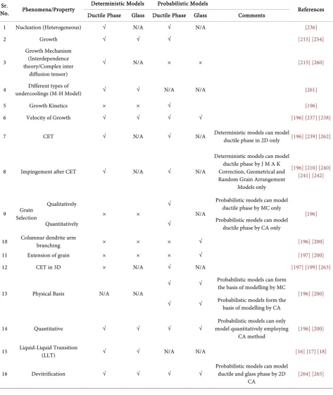
during Solidification
Stage 1 Model: These models take into account the mechanism of 1) grain nu-cleation and 2) grain growth in alloys which are solidifying with equiaxed den-drite or eutectic microstructures [236]. These do not account for alloys which are solidifying with columnar dendritic and planar interfaces. A modification of these accounts for equiaxed-columnar (at mould wall) and columnar to equiaxed transition (CET) in bulk of liquid. These can be used to “describe microstruc-tures” and “prediction of grain size” in case of eutectic compositions of BMGMC. Majority of these is based on “analytical/deterministic approaches” which can be described as follows;
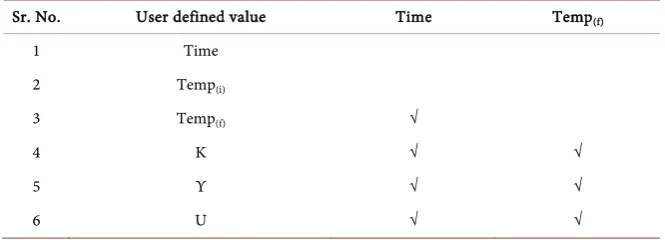
8.5.1. Nucleation
1) Choose a time “t” (initially non-zero value)
2) At this time t, density of grains (which have nucleated in bulk) is a function of undercooling
(
n)
d f= ∆T (2) f(ΔTn) is difficult to be found from theoretical considerations alone. It needs to be found experimentally i.e. form a set of experiments e.g.
Method 1 Measurement of cooling curve.
This has been explained in detail in Section 7.2.1. and 7.2.2.
Method 2 Measurement of grain density (optical micrograph of cross section (using Image J/ASTM 562 - 11 Method)) for specimens solidified at various
cooling rates [196].
8.5.2. Growth
As soon as grain has nucleated, and its growth can be explained by special
fied case of classical nucleation theory (CNT) for BMGMC (A detailed treatment of modified CNT for BMGMC is given in Appendix A) and its distribution can be explained by constitutional supercooling zone/Interdependence theory (propagation of liquid-solid interface/liquid-solid spherical front)—a possibility which is still under investigation by author for suitability for additive manufac-turing processes), it grows with an interface velocity which is also a function of undercooling.
8.5.3. Velocity of Growth
Velocity of growth may be written as
(
)
g n
V = f ∆T (3)
In this case, there is no need to determine solidification kinetics of dendrite tip/eutectic (spherical front) interface by cooling curve or grain size but it can be determined by theoretical models developed (by using basic laws of physics) [237] [238] as applied to BMGMC only under transient condition.
8.5.4. Impingement and Columnar to Equiaxed Transition (CET)
Impingement of grains as they grow is another important phenomenon which for all practical reasons governs the shape of grain after columnar to equiaxed transition (CET) (CET in additive manufacturing is recently explained by Am-rita Basak etal.[239] which is combined with present model and is explained in detail in Appendix B). This phenomenon is not remarkably present in bulk me-tallic glass and their composites due to their sluggish nature and slightly formed crystal grains as compared to huge glassy matrix. However, despite these draw-backs, this is mainly responsible for equiaxed dendritic grain formation even in glassy alloys, especially in eutectic compositions which is assumed to be the case for present research.
This has been typically treated by
1) Standard J M A K [210] [240] correction or by 2) Geometrical [241] [242] or
3) Random grain arrangement models [196]
These “microscopic” solidification models have been coupled with “macro-scopic” transient one-dimensional (1D) heat flow calculations to successfully predict “microstructural features” specially “grain size” at the scale of whole process (part scale) [243] [244].
8.5.5. Limitations
These deterministic models have their following limitations 1) Grain selection
They cannot account for the “grain selection” which occurs
a) Close to mould region/surface giving rise to columnar dendritic micro-structure (in case of conventional Cu mould suction casting/twin roll casting (TRC)) or
b) At surface of external inoculant particles (precursors of heterogeneous
cleation) in case of well inoculated melts (present case)) giving rise to onset of columnar dendritic microstructure (at a very small length scale) since they al-most neglect any aspect which is related to crystallographic effects.
2) “Equiaxed-Columnar” Transition
They cannot predict the co-called “equiaxed-columnar” transition which oc-curs very near to mould wall [245] or variation of transverse size of columnar grains [246] (also known as columnar dendritic arm branching). This is ex-plained in detail in individual cases for each type of metal (crystal structure).
Case 1: Cubic Metals
It is well established facts that for cubic metals, this “grain selection” is based upon a criterion of best alignment” of the < 100 > crystallographic axes of grain with heat flow direction [245] [246] [247]. Thus, this method cannot account for this anisotropic behaviour of heat flow. A solution to this problem could be proposed by determining best fit direction by use of recent developments in crystallography and their application to solidification. Edgeto edge matching (E2EM): One way is to use Edge-to-Edge Matching (E2EM) technique at inocu-lant-ductile phase level (in case of Zr based BMGMC) (present research). This gives rise to selection of suitable potent nuclei of certain size and specific pre-ferred orientation (i.e. along a defined easy crystallographic plane (e.g. (001)). If this crystallographic plane direction could be used in conjunction with macro-scopic heat flow models, it can give rise to “prediction or selection of grain”. In other words, if matching crystallographic axes (suitable for a potent inoculant selection for CuZr-B2 ductile phase’s preferred precipitation (in case of BMGMC)) could be best aligned with heat flow direction (or heat flow direction could be assigned to this preferred matching crystallographic axes) a best “grain selection: could be determined (one of aim of present research—not done pre-viously elsewhere). This type of phenomena is particularly important in
a) Directional solidification (DS) or
b) Production of single crystal dendritic alloys for aerospace applications or c) Production of BMGMC by Bridgeman solidification
Note: This is in addition to use of E2EM for selection of potent nuclei Case 2: BCC Metals
These methods are also ineffective in predicting “equiaxed-columnar” and then “branching of dendrite arms” in bcc metals (i.e. grain selection) as best alignment between heat flow and crystallographic direction is not well known. Only assumptions are possible (i.e. in case of bcc best heat flow direction could be assigned to close packed direction).
Case 3: FCC Metals
These methods are again ineffective in predicting the “equiaxed - columnar”, “CET” and then branching of dendrite arms in fcc metals (i.e. grain selection) as best alignment between heat flow and close packed direction (111) could only be assumed (to a satisfactory qualitative level). More quantitative experimentation is needed to determine best directions along which heat flow occurred or revert
to more advanced models.
3) Extension of a grain into an open region of liquid.
They cannot account for extension of a grain into an open region of liquid. 4) Columnar-to-Equiaxed Transition (CET)
Finally, when very fine equiaxed grains at a region very close to mould wall/right at the interface of inoculant and melt are converted to columnar grains, which when grow, there comes a point/plane at which columnar grains gets converted to not so fine equiaxed grains. This point is known as columnar to equiaxed transition (CET). These equiaxed grains finally extend towards cen-tre of casting (wedge shape/melt pool cencen-treline in case of additive manufactur-ing). CET primarily happens as a result of thermal fluctuations which happen at melt (liquid) and solid (solidified melt) interface which are triggered by solutal effects as well as heat extraction or absorption due to phase changes occurring at a micro-scale (explained in subsequent sections). CET is dominant when ther-mal gradient is sther-mall.
8.6. Evolution of Probabilistic Models
The solution to above four problems is presented first by Brown and Spittle [248] [249]. They developed probabilistic models. They used monte carlo (MC) procedure for explaining solidification phenomena developed in earlier research [250]. MC method is based upon minimising of interfacial energy (which is practically calculated by using physical properties of material (Zr- and Fe-based BMGMC)) from literature and earlier published data or inference from extrapo-lation or interpoextrapo-lation of data as needed). Procedurally, this minimisation is achieved by
1) Considering the energy of “unlike sites” (e.g. (a) “liquid/solid sites” or (b) “sites belonging to different grains” and
2) By allowing transition between these states to occur according to randomly generated numbers
By using this method, Brown and Spittle merely able to produce computed 2 D microstructures which resembled very closely to those observed in real micrographic cross section. In particular
a) The selection of grains in the columnar zone and b) Columnar to equiaxed transition (CET)
were nicely reproduced using this technique also a) the effect of solute concentration or
b) melt superheat upon the resultant microstructure
was determined “qualitatively” in a nice way. Their quantitative representation was not achieved.
Limitations
These methods suffer consistently from lack of physical basis and thus cannot be used to analyse quantitatively the effect of various physical phenomena (hap-pening within the phase transformations). For example, to illustrate this,
sider the following example.
1) During one monte carlo (MC) time step, Consider N sites where N is number of sites whose evolution is calculated and is chosen from another N (to-tal number) sites. Therefore, not all sites of interest (i.e. those located near to solid-liquid interface) are investigated. This in turn, leads to algorithm predicted grain competition in columnar region, which does not at all reflect the physical mechanisms observed in organic alloys.
2) Furthermore, the results are sensitive to type of Monte Carlo (MC) network itself which is used for computations. Thus, a single powerful model is presented in present work which combines “advantages of probabilistic methods with those of deterministic approaches” to predict more accurately the grain structure in a casting.
8.7. Two-Dimensional Cellular Automaton (CA) Method
For this purpose, for now, a 2D Cellular Automaton model is developed which is based upon physical mechanisms of nucleation and growth of dendritic grains. Its salient features are as follows;
1) Heterogeneous nucleation; which was modelled by means of a nucleation site distribution in deterministic solidification models, is treated in a similar way in present probabilistic approach.
2) If total density of grains which nucleate at a given undercooling is obtained from an average distribution (dc = average (distribution)), the location of these sites is chosen randomly
1 2 3 4 5 n
c
a a a a a a
d
n
+ + + + + +
= (4)
where a a a a1, , , , ,2 3 4 an are distributions of grains 1, 2, 3 to n.
where n = R (R = Real numbers).
3) Crystallographic orientation of a newly nucleated grain is also taken into account at random.
4) The growth kinetics of (a) dendrite tip and (b) of side branches are also in-corporated into the model in such a way that final simulated microstructure is independent of the “cellular automaton network” which is used for computa-tions.
Although, it produces micrographic cross sections very much similar to those already obtained by Brown and Spittle, present model has a “sound physical ba-sis” and can thus reflect effects of (a) cooling rate” or (b) “solute concentration” quantitatively.
8.7.1. Detailed Description (Phase 1—Application of CAFE to Conventional Casting)
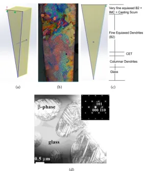
Physical background: Consider a BMGMC wedge shape casting as shown in Figure 3 below.
Figure 3(c) is typical 2D cross section of cast eutectic Zr-based BMGMC
(a) (b) (c)
[image:22.595.232.517.65.401.2](d)
Figure 3. (a) Schematic 3D (b) Optical Micrograph of cross section (etched) (c) 2D Schematic showing regions (d) A specific region (from B2 dendrites) showing B19’ twins (B2 - B19’ TRIP).
solidified in water cooled wedge shape Cu-mould [78] [251]. Their dendritic grains which have various crystallographic orientations appear as zones of dif-ferent colours (Figure 3(b)). Most common regions encountered in any casting appear here [245] [246] and are marked all along cross-section. On the top end of wedge shape ingot coarse grains are present as this region was exposed to air. Its more detailed explanation will follow after characterizing region chronologi-cally from bottom to top.
8.7.2. Characterization
Bottom region glass: The tip of casting is 100% glass (monolithic BMG). This re-gion is classified as glass and no crystal structure is observed here because cool-ing rate is maximum here which results in extraction of heat at a very high rate resulting in retaining supercooled liquid state at room temperature.
Bottom region: columnar dendrites: This region marks the beginning of “equiaxed columnar” first transition. This consists of very fine layer in which this transition happens, and then columnar grains grow (primarily) in random 3D orientation) because of still rapid rate of heat transfer which is comple-mented by sluggish nucleation on growth mechanisms of BMGMC. These grains
are not very long as heat flow pattern is somewhat exponential because of wedge shape casting which triggers next transition too quickly before extension of growth as predicted by kinetics. This helps in retaining glassy matrix all throughout the casting. Otherwise 100% crystallisation would have happened.
Bottom region: columnar to equiaxed transition (CET): This is the region in which columnar dendritic grains which have developed/grown to a satisfactory level, transit to equiaxed grains, known as CET. This is triggered by various phenomena such as solute diffusion, solute-solvent partitioning, shape of uid-solid propagation front, thermal fluctuations happening at the tip of liq-uid-solid propagating interface.
Fine equiaxed dendrites (CuZr-B2): Once CET happens, equiaxed dendrites are formed all throughout the casting. Only their shape differs. In this region, they are fine sized while in Top Region, their size is even more reduced due to presence of IMCs. Casting scum and other impurities coupled with faster cool-ing rate from open top (convection and radiation) and side walls (conduction). NOTE: In case of bulk metallic glass matrix composites (BMGMC) not only inoculant particles serve as sites for heterogeneous nucleation, but grain boundaries also serve this purpose [252] [253]. Other defects and solidification microstructure also serve as sites for heterogeneous nucleation (their effects in total solidification (nucleation and growth model) are to be considered in final model).
9. Conclusions
Despite their recent popularity and emblem to be exploited as potential struc-tural engineering material for extreme applications, still, an in-depth under-standing of underlaying mechanisms responsible for formation of glass and nu-cleation of ductile phase during solidification in bulk metallic glass and their composites is at an arm’s length from the limit of satisfaction. Various theories and mechanisms such as phase separation, liquid-liquid transition, frustration, ordering and confusion have been proposed to account for development of duc-tility in these diverse classes of materials, but none have proved out to be fully satisfactory. These studies have been backed by strong and powerful experimen-tal techniques such as observation under synchrotron light employing container less levitated conditions and observation of nucleation and growth under micro and zero gravity conditions on board international space station. An innovative technique known as additive manufacturing, has recently emerged as competi-tive method for the large-scale production of metals and alloys including bulk metallic glass matrix composites. It intrinsically, engulfs applicability and im-plementation of all important phenomena responsible for development of in-situ dendrite reinforced microstructure in these alloys. However, like conventional methods, it also poses challenges to produce high quality components quickly. Evolution of melt pool and microstructure in it are two main important pa-rameters to control. Part and material loss is inevitable to investigate the root
cause of these problems. This study is an attempt to bridge both these gaps. A concise review of existing literature on bulk metallic glass and their composites is followed by introduction of coupled microscale simultaneous heat and mass model accounting for development of liquid melt pool in additive manufactur-ing and microstructure in it. Two-dimensional probabilistic cellular automaton method is combined with one dimensional non-linear heat transfer method based on finite element method to predict heat transfer pattern and microstruc-ture in rapidly solidifying liquid melt pool in additive manufacturing. It is shown systematically, that step-by-step application of model with the use of actual heat and mass transfer (diffusion) coefficients at every step of solidification is the so-lution of problem. Transient conditions are adopted by implementation of itera-tive technique using FORTRAN and MATLAB languages for programming
and commercial simulation package ABAQUS for parallel visual simulation.
This is the first study of its kind emphasizing the need and importance of mod-elling and simulation in predicting solidification phenomena (heat transfer pat-tern and microstructure based on solute diffusion and capillary action) in addi-tive manufacturing of bulk metallic glass and their composites.
Acknowledgements
Author greatly acknowledges the time spent in reading and correcting the manuscript by Dr. Mark Gibson and for his helpful suggestions and positive constructive criticism. He also thanks and acknowledges the moral support, al-ways welcoming attitude and time for technical discussions provided by Prof. Milan Brandt.
References
[1] Klement, W., Willens, R.H. and Duwez, O.L. (1960) Non-Crystalline Structure in Solidified Gold-Silicon Alloys. Nature, 187, 869-870.
https://doi.org/10.1038/187869b0
[2] Chen, H.S. (1974) Thermodynamic Considerations on the Formation and Stability of Metallic Glasses. ActaMetallurgica, 22, 1505-1511.
https://doi.org/10.1016/0001-6160(74)90112-6
[3] Greer, A.L. (1995) Metallic Glasses. Science, 267, 1947-1953.
https://doi.org/10.1126/science.267.5206.1947
[4] Güntherodt, H.J. (1977) Metallic Glasses. In: Treusch, J., Ed., Festkörperprobleme
17: Plenary Lectures of the Divisions “Semiconductor Physics” “Metal Physics” “LowTemperaturePhysics” “ThermodynamicsandStatisticalPhysics” “ Crystallo-graphy” “Magnetism” “SurfacePhysics” ofthe GermanPhysical SocietyMünster, Springer, Berlin, Heidelberg, 25-53.
[5] Inoue, A. (1995) High Strength Bulk Amorphous Alloys with Low Critical Cooling Rates (<I>Overview</I>). MaterialsTransactions, JIM, 36, 866-875.
https://doi.org/10.2320/matertrans1989.36.866
[6] Johnson, W.L. (1999) Bulk Glass-Forming Metallic Alloys: Science and Technology.
MRSBulletin, 24, 42-56. https://doi.org/10.1557/S0883769400053252
[7] Matthieu, M. (2016) Relaxation and Physical Aging in Network Glasses: A Review.
ReportsonProgressinPhysics, 79, Article ID: 066504.
https://doi.org/10.1088/0034-4885/79/6/066504
[8] Hofmann, D.C. and Johnson, W.L. (2010) Improving Ductility in Nanostructured Materials and Metallic Glasses: “Three Laws”. In Materials Science Forum, Trans Tech Publications, Zurich.
[9] Shi, Y. and Falk, M.L. (2006) Does Metallic Glass Have a Backbone? The Role of Percolating Short Range Order in Strength and Failure. Scripta Materialia, 54, 381-386. https://doi.org/10.1016/j.scriptamat.2005.09.053
[10] Mattern, N., etal. (2009) Short-Range Order of Cu-Zr Metallic Glasses. Journalof AlloysandCompounds, 485, 163-169.
https://doi.org/10.1016/j.jallcom.2009.05.111
[11] Jiang, M.Q. and Dai, L.H. (2010) Short-Range-Order Effects on Intrinsic Plasticity of Metallic Glasses. PhilosophicalMagazineLetters, 90, 269-277.
https://doi.org/10.1080/09500831003630781
[12] Zhang, F., et al. (2014) Composition-Dependent Stability of the Medium-Range Order Responsible for Metallic Glass Formation. ActaMaterialia, 81, 337-344.
https://doi.org/10.1016/j.actamat.2014.08.041
[13] Sheng, H.W., etal. (2006) Atomic Packing and Short-to-Medium-Range Order in Metallic Glasses. Nature, 439, 419-425. https://doi.org/10.1038/nature04421 [14] Cheng, Y.Q., Ma, E. and Sheng, H.W. (2009) Atomic Level Structure in
Multicom-ponent Bulk Metallic Glass. PhysicalReviewLetters, 102, Article ID: 245501.
https://doi.org/10.1103/PhysRevLett.102.245501
[15] Inoue, A. and Takeuchi, A. (2011) Recent Development and Application Products of Bulk Glassy Alloys. ActaMaterialia, 59, 2243-2267.
https://doi.org/10.1016/j.actamat.2010.11.027
[16] Wei, S., etal. (2013) Liquid-Liquid Transition in a Strong Bulk Metallic Glass-Forming Liquid. NatureCommunications, 4, Article No. 2083.
https://doi.org/10.1038/ncomms3083
[17] Zu, F.-Q. (2015) Temperature-Induced Liquid-Liquid Transition in Metallic Melts: A Brief Review on the New Physical Phenomenon. Metals, 5, 395.
https://doi.org/10.3390/met5010395
[18] Lan, S., etal. (2016) Structural Crossover in a Supercooled Metallic Liquid and the Link to a Liquid-to-Liquid Phase Transition. AppliedPhysicsLetters, 108, Article ID: 211907. https://doi.org/10.1063/1.4952724
[19] James, P.F. (1975) Liquid-Phase Separation in Glass-Forming Systems. Journalof MaterialsScience, 10, 1802-1825. https://doi.org/10.1007/BF00554944
[20] Greer, A.L. (1993) Confusion by Design. Nature, 366, 303-304.
https://doi.org/10.1038/366303a0
[21] Nelson, D.R. (1983) Order, Frustration, and Defects in Liquids and Glasses. Physical ReviewB, 28, 5515-5535. https://doi.org/10.1103/PhysRevB.28.5515
[22] Ma, E. (2015) Tuning Order in Disorder.NatureMaterials, 14, 547-552.
https://doi.org/10.1038/nmat4300
[23] Greer, A.L. (2006) Liquid Metals: Supercool Order. NatureMaterials, 5, 13-14.
https://doi.org/10.1038/nmat1557
[24] Liu, X.J., etal. (2010) Metallic Liquids and Glasses: Atomic Order and Global Pack-ing. PhysicalReviewLetters, 105, Article ID: 155501.
https://doi.org/10.1103/PhysRevLett.105.155501
[25] Wang, W.H. (2012) Metallic Glasses: Family Traits. NatureMaterials, 11, 275-276.
https://doi.org/10.1038/nmat3277
[26] Kumar, G., Desai, A. and Schroers, J. (2011) Bulk Metallic Glass: The Smaller the Better. AdvancedMaterials, 23, 461-476. https://doi.org/10.1002/adma.201002148
[27] Drehman, A.J., Greer, A.L. and Turnbull, D. (1982) Bulk Formation of a Metallic Glass: Pd40Ni40P20. AppliedPhysicsLetters, 41, 716-717.
https://doi.org/10.1063/1.93645
[28] Kui, H.W., Greer, A.L. and Turnbull, D. (1984) Formation of Bulk Metallic Glass by Fluxing. AppliedPhysicsLetters, 45, 615-616. https://doi.org/10.1063/1.95330
[29] Nishiyama, N., etal. (2012) The World’s Biggest Glassy Alloy Ever Made. Interme-tallics, 30, 19-24. https://doi.org/10.1016/j.intermet.2012.03.020
[30] Qiao, J., Jia, H. and Liaw, P.K. (2016) Metallic Glass Matrix Composites. Materials ScienceandEngineering: R: Reports, 100 1-69.
https://doi.org/10.1016/j.mser.2015.12.001
[31] Chen, H.S. (1980) Glassy Metals. ReportsonProgressinPhysics, 43, 353.
https://doi.org/10.1088/0034-4885/43/4/001
[32] Turnbull, D. (1969) Under What Conditions Can a Glass Be Formed? Contempo-raryPhysics, 10, 473-488. https://doi.org/10.1080/00107516908204405
[33] Akhtar, D., Cantor, B. and Cahn, R.W. (1982) Diffusion Rates of Metals in a NiZr2 Metallic Glass. ScriptaMetallurgica, 16, 417-420.
https://doi.org/10.1016/0036-9748(82)90164-8
[34] Akhtar, D., Cantor, B. and Cahn, R.W. (1982) Measurements of Diffusion Rates of Au in Metal-Metal and Metal-Metalloid Glasses. ActaMetallurgica, 30, 1571-1577.
https://doi.org/10.1016/0001-6160(82)90177-8
[35] Akhtar, D. and Misra, R.D.K. (1985) Impurity Diffusion in a NiNb Metallic Glass.
ScriptaMetallurgica, 19, 603-607. https://doi.org/10.1016/0036-9748(85)90345-X [36] Inoue, A., Zhang, T. and Masumoto, T. (1993) Glass-Forming Ability of Alloys.
JournalofNon-CrystallineSolids, 156, 473-480.
https://doi.org/10.1016/0022-3093(93)90003-G
[37] Lu, Z.P., Liu, Y. and Liu, C.T. (2008) Evaluation of Glass-Forming Ability. In: Mil-ler, M. and Liaw, P., Eds., BulkMetallicGlasses, Springer, Boston, MA, 87-115.
https://doi.org/10.1007/978-0-387-48921-6_4
[38] Yi, J., etal. (2016) Glass-Forming Ability and Crystallization Behavior of Al86Ni9La5 Metallic Glass with Si Addition. AdvancedEngineeringMaterials, 18, 972-977. [39] Wang, L.-M., etal. (2012) A “Universal” Criterion for Metallic Glass Formation.
AppliedPhysicsLetters, 100, Article ID: 261913. https://doi.org/10.1063/1.4731881
[40] Donald, I.W. and Davies, H.A. (1978) Prediction of Glass-Forming Ability for Me-tallic Systems. JournalofNon-CrystallineSolids, 30, 77-85.
https://doi.org/10.1016/0022-3093(78)90058-3
[41] Park, E.S. and Kim, D.H. (2005) Design of Bulk Metallic Glasses with High Glass Forming Ability and Enhancement of Plasticity in Metallic Glass Matrix Compo-sites: A Review. MetalsandMaterialsInternational, 11, 19-27.
https://doi.org/10.1007/BF03027480
[42] Chen, M. (2011) A Brief Overview of Bulk Metallic Glasses. NPGAsiaMaterials, 3, 82-90. https://doi.org/10.1038/asiamat.2011.30
[43] Park, E.S., Chang, H.J. and Kim, D.H. (2008) Effect of Addition of Be on Glass-Forming Ability, Plasticity and Structural Change in Cu-Zr Bulk Metallic