Hybrid Sliding Mode Control Technology of Electric
Vehicle Based on Wireless Sensor
https://doi.org/10.3991/ijoe.v13i05.7052
Wenfang Zheng
Xinxiang Vocational and Technical College, Henan, China [email protected]
Jincui Liu
Xinxiang Vocational and Technical College, Henan, China [email protected]
Abstract—The purpose of this study is to solve defects of the existing con-trol strategy long convergence time, sliding mode chattering and so on. For Sensorless Brushless DC motor control strategy, a modified extended Kalman state correction estimation scheme is proposed, and dual mode high-order non-singular terminal hybrid sliding mode control technology is put forward. TMS320F2812DSP core controller and CM200DY-12H inverter module and construction electric car core control module are established, and the program algorithm of the extended Kalman algorithm and hybrid sliding mode control is constructed. The results showed that the control system designed can suppress the system chattering, and the system has strong robustness, which has low re-quirement on the system model and can eliminate external disturbance input, showing outstanding performance in the convergence time and anti disturbance performance. In summary, a dual mode high-order non-singular terminal hybrid sliding mode control technology put forward is quite suitable for electric vehi-cle control system.
Keywords—Sensorless, electric vehicle, hybrid sliding mode control
1
Introduction
innovation and innovation in the automotive field [1]. Due to the complexity of the electric vehicle driving environment, load changes, the upper and lower slopes, high temperature, body vibration and other factors put forward high requirements on the electric vehicle control strategy. Sliding mode control (SMC), as an effective nonline-ar control technique, through the design of the sliding mode hyperplane, makes the system state into sliding mode and tend to be stable. Because of its low precision and strong robustness to external disturbance and disturbance input, it is widely concerned in the control system of electric vehicle [2]. However, the existing sliding mode con-trol strategy has some disadvantages such as long convergence time and chattering. Brushless DC motor needs rotor pole position signal to provide phase-change infor-mation for the switch circuit to achieve effective control. But the position sensor is easy to be damaged in a complex environment, and susceptible to electromagnetic interference, resulting in the reduction of the service life of motor and limited by the environment. As a result, sensorless brushless DC motor control strategy has become a hot research topic [3].
This study makes an in-depth analysis of electric vehicle using brushless DC motor control mathematical model, for sensorless brushless DC motor control strategy, pro-poses a modified extended Kalman state correction estimation scheme, conducts in-depth study of sliding mode control strategy, and for normal driving and energy feed-back stage, puts forward a kind of dual mode high-order nonsingular hybrid terminal sliding mode control technique.
2
State of the art
Opposite to a brush DC motor, a brushless DC motor, has a fixed armature, with-out using mechanical brush device. Instead of the traditional brush and commutator through the position sensor and electronic commutation device, the armature can be directly connected with the electronic commutation devices, such as transistors, MOSFET or IGBT. The position sensor is located inside the motor, the rotor position is detected in real time, and the magnetic field direction is controlled by electronic phase change device. The electronic commutation device consists of inverter and controller. The inverter converts the DC power supply to the motor control signal, and the controller realizes the control effect through the real-time control of the inverter according to the control demand.
The brushless DC motor control is a strongly coupled nonlinear dynamic system, and the mathematical model of the motor based on the dynamic structure is uncertain and the measurement data is easily polluted by noises. When the motor model error is controlled in the allowable range and the statistical characteristics of the random noise are known, the system operating state can be identified. As an algorithm extension in nonlinear systems, the extended Kalman filtering, as Kalman filtering, belongs to the state estimation identification in the sense of minimum variance estimation. Based on the on-line accumulation and update of the process information, the identification model is modified to reduce the uncertainty of the controlled system, and thus realiz-ing sub-optimal state identification for nonlinear systems.
When the extended Kalman is applied to electric vehicle brushless DC motor con-trol system, real-time feature of the algorithm requires that the algorithm can quickly calculate. However, because extended Kalman has a more matrix multiplication cal-culations, it will undoubtedly bring great challenge to the real-time system. But now the high performance digital processing chip has become more and more popular, so it provides a good basis for the realization of extended Kalman on electric vehicles [5]. Therefore, this study will make an analysis on the application of expand Kalman in the sensorless control system of Brushless DC motor for electric vehicles.
The traditional brushless DC motor for electric vehicles requires position sensors to obtain rotor position information, which can achieve accurate commutation control. Because the position sensor will lead to the decrease of the service life of the motor, the sensorless BLDCM control strategy has gradually become a research hotspot.
Ruan Zhaozhong studied the application of position sensorless technology in BLDCM control system and its most mature back electromotive force method in rotor position detection technology. By analyzing the brushless DC motor, he studied the working principle of the BLDCM control system, the position sensorless control pro-cess and the back electromotive force method to detect the rotor position. At last, he elaborated the hardware design and software design of the BLDCM system and power experiment.
Based on the analysis of the working principle of the brushless DC motor, Gao Zhengzhong and Zhang Xiaoyan have proposed a BLDCM control system based on STM32 sensorless sensor. They use hardware to obtain commutation points, thereby reducing the performance requirements of the controller. The system mainly includes commutation point detection circuit, motor drive circuit, current detection and protec-tion circuit, communicaprotec-tion interface and so on. Using the speed and current double closed-loop control, which stabilizes the output torque of the motor and improves the response speed of the motor, the experimental results show that the design has the characteristics of high control precision, fast response, stable and reliable operation.
In summary, the working environment of the electric vehicle is complicated, and the system parameters are susceptible to interference. The conventional control algo-rithm is difficult to achieve satisfactory results. In order to realize the accurate com-mutation control, brushless DC motor for traditional electric vehicle needs position sensor to obtain the rotor position information. The current control strategy cannot accurately track the effect of time-varying variables on the control results. The sliding mode control strategy has some disadvantages such as long convergence time and chattering. Therefore, our aim is to solve the existing control strategy long conver-gence time, sliding mode chattering and so on defects. For Sensorless Brushless DC motor control strategy, a modified extended Kalman state correction estimation scheme is proposed, and dual mode high-order non-singular terminal hybrid sliding mode control technology is put forward. TMS320F2812DSP core controller and CM200DY-12H inverter module and construction electric car core control module are established, and the program algorithm of the extended Kalman algorithm and hybrid sliding mode control is constructed.
3
Methods
3.1 Extended Kalman filter algorithm
As an algorithm in nonlinear system, the extended Kalman filter is the expansion and extension of the Kalman filter algorithm in nonlinear system. Brushless DC motor for electric vehicle is a typical nonlinear system, and the realization of the state esti-mation of the system needs a kind of algorithm theory that can be applied to nonlinear system. In order to realize the application of Kalman filtering algorithm in nonlinear system, a new algorithm is proposed, which is called extended Kalman filter.
The running state model of brushless DC motor for electric vehicle can be ex-pressed by general equation as follows [6]:
[ ]
[ ]
(
)
(
)
)
(
)
(
)
(
)
(
)
(
t
t
x
h
t
y
t
t
BV
t
x
f
t
x
µ
!
+
=
+
+
=
!
(1)
In (1),
!
(
t
)
refers to the system noise, andµ
(
t
)
indicates the measurement noise. Both of the two are Gauss white noise with zero mean, whose co-variance are)
(
t
Q
andR
(
t
)
, respectively.The Kalman filter equation for estimation error is:
In (2),
"
x
ˆ
k!1 refers to the state estimation error of the momentk
!
1
, and!
y
ˆ
kindicates the observed estimation error of the moment
k
!
1
. Both of the two have the following relationship:)
ˆ
(
ˆ
ˆ
ˆ
1 / 1 1 1 1 ! ! ! ! !!
=
"
!
=
"
k k k k k k kx
h
y
y
x
x
x
(3)The optimal estimation of the linear equation is given, and assuming that the ob-tained estimated value is optimal, that is
!
x
ˆ
k"1=
0
. From the above equation, we canobtain
!
x
ˆ
k/k"1=
0
, and according to the principle of linear change, we can get thenonlinear discrete extended Kalman filter equation, as follows:
T k k k T k k k k k k k k T k k k k k k T k k k k T k k k k k k k k k k k k c k k k k k k
K
R
K
H
K
I
P
H
K
I
P
Q
P
P
R
H
P
H
H
P
K
x
H
y
K
x
x
T
V
B
x
x
+
!
!
=
+
=
+
=
!
+
=
+
"
=
! ! ! ! ! ! ! ! ! ! ! ! !)
(
)
(
)
(
)
ˆ
(
ˆ
ˆ
ˆ
ˆ
1 / 1 1 1 / 1 1 / 1 / 1 / 1 / 1 1 1 1 /#
#
#
(4)3.2 System hardware design
The hardware design of the system is mainly composed of processor, inverter cir-cuit, protection circuit and sampling circuit. The processor determines the control speed of the system, and the inverter circuit conducts the motor input signal control, protects the circuit to make real-time protect of the system, to prevent overload, over-current and short circuit and so on [7]. The sampling circuit is used to collect the running information in real time, which is supplied to the controller to calculate and realize the state identification and control output.
The structure of the electric vehicle and the relationship between each module and the drive system are shown in Figure 1.
In processor selection, it is necessary to consider that, in the design of sliding mode control law, there is the presence of differential and integral link, needing a processor with a strong digital processing ability and in the sliding mode controller, if needing to weaken the chattering, it needs to be able to have the ability of high frequency switching in practice. All of these control requirements put forward higher require-ments for the processor's digital processing capability. Therefore, we choose the pro-fessional motor digital signal processing chip TMS320F2812 under TI company as the core processor.
and 600V(
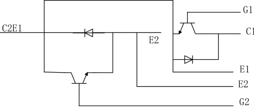
u
ce) load. The internal structure of the MITSUBISHI CM200DY-12H is shown in Figure 2.Controller
Power Battery
Drive System Variable speed drive system
Body chassis
wheel Energy management
Variable speed control Drive control
Fig. 1. Schematic diagram of structure and module of electric vehicle
Fig. 2. Temperature controller system structure
The isolation circuit of the system adopts the Si826x chip. The chip can directly replace the traditional photoelectric coupler to achieve isolation driving function, mainly used in motor control and drive industrial field, which is a special motor driver chip, very suitable for used in the driving circuit of IGBT.
Uin
+
-+
-U1
Tr
FUSE1
Rv
Lt1
VD1-VD4
Rt
+
-Uout
Fig. 3. System power module schematic
The protection circuit is composed of Rave, FUSEl, Ltl and Rt. Rv refers to the varistor resistance. When the input voltage is too large or there is surge voltage, the resistance decreases rapidly, thereby inhibiting the voltage disturbance. FUSEl is the fuse, and when the current is too large, it will fuse out. Ltl is a filter coil, which is used to eliminate electromagnetic interference in the circuit. Rt is a thermistor, whose characteristic is that it increases with the increase of temperature resistance. When the instantaneous large current appears in the circuit, the resistance temperature rises and the resistance value enlarges, so the current is reduced, to play the role of protecting the circuit.
3.3 System software design
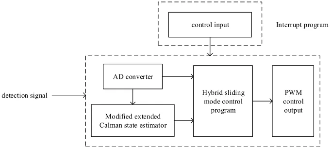
The system software design is divided into two modules: modified extended Kal-man state estimation and hybrid sliding mode control algorithm. In order to ensure the smooth realization of the control system, it is necessary to improve other functional design. The overall block diagram of the system software design is shown in Figure 4.
AD converter
Modified extended Calman state estimator
Hybrid sliding mode control
program
PWM control output control input
detection signal
Interrupt program
main program
It can be seen from Figure 3 that, the main program needs to deal with the accept-ing and convertaccept-ing of the detection signal, make state estimation program of extended Kalman, input to the hybrid sliding mode control algorithm, and finally perform out-put control through the PWM wave, to achieve the effect of stable control of electric vehicle.
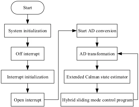
Figure 5 is the program design flow chart.
Start
System initialization
Off interrupt
Interrupt initialization
Open interrupt
Start AD conversion
AD transformation
Extended Calman state estimator
Hybrid sliding mode control program
Fig. 5. System main program flow chart
From the program flow chart, it can be seen that, the system input program is achieved through the system interrupt. The purpose of the design is, if the interruption program has been in a state of triggering, it will affect the normal execution of the main program of the system. As a result, in the program design, the principle to fol-low is to set the interruption program to the task with fol-low triggering frequency or taking up less time.
In the process of program operation, the input frequency of the system belongs to the lower level compared with the CPU state estimation and the system output fre-quency. The system input program takes up a short time, so the system input is set to interruption triggering mode. The system state estimation, AD conversion and control output are implemented in the main program.
Start
The input value of the system, the AD conversion value, the extended Calman state estimation
Differential algorithm, the deviation and the input derivative
Control mode judgment
Normal mode sliding surface
Normal mode design
Normal mode control output
The end
Energy feedback sliding surface
Energy feedback design control
Energy feedback control output Normal driving mode
Energy feedback model
Fig. 6. Hybrid sliding mode controller program flow chart
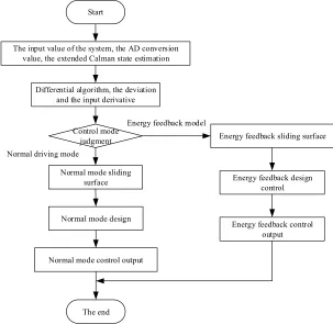
The output of the controller is obtained according to the calculation. That is to say, the inverter output control can be carried out through the PWM generator. From the program flow chart, it can be seen that, when the control algorithm is realized, it re-quires a judge, to choose to conduct normal driving control or energy feedback con-trol. Since that differential control and differential input deviation in the two schemes are necessary for calculation, the differential calculation link is set before the judg-ment.
4
Experiment
4.1 Experiment process
electromotive force constant is
k
e=
0
.
85
V
/
rpm
, and permanent magnet isWb
f
=
0
.
368
!
. In normal driving mode, make a performance comparison study of modified extended Kalman estimation strategy the unmodified modified Kalman estimation strategy.4.2 Experimental results and discussion
When using hybrid sliding mode control for state estimation of modified extended Kalman estimation and unmodified extended Kalman estimates two strategies, from the system speed tracking error comparison, it can be known that, without extended Kalman correction, system speed tracking error is relatively large, vulnerable to ex-ternal interference. While after the amendment, the state estimation process has strong external disturbance rejection ability, the state estimation error decreases, and the estimation stability is enhanced.
The results show that both of them have good performance in response time of the system in the case of no disturbance in the track test of hybrid sliding module and traditional sliding module for step input, and the results show that both of them have no overshoot in traditional Pl control. And the performance of the hybrid sliding mode control is better than that of the traditional uniform order sliding mode control in buffeting suppression and tracking stability.
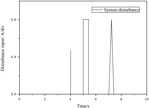
Figure 7 shows to add the human system in the implementation platform, that is to say, to add the disturbance diagram of the peak disturbance pulse in the system obser-vation value. The system obserobser-vation value is an and b two-phase current, the set disturbance writes through the program, and conduct preset in advance in the AD conversion process.
! " # $ % &!
!'! !'# !'%
Di
st
urb
ance
in
pu
t/ A/
di
v
Time/s
(System disturbance
(
(
Under the disturbance input of the above figures, the system can carry out the en-ergy feedback mode operation, and the results show that the hybrid sliding mode controller is superior to the traditional PI control when the system is disturbed. The velocity tracking is stable, which can well restrain the influence of the disturbance of the observation value on the velocity tracking.
The experiments show that the hybrid sliding mode control can realize double mode speed tracking and suppress the system buffeting, and the system has strong robustness, having low requirement on the system model, able to eliminate the exter-nal disturbance input, and being excellent in the convergence time and anti disturb-ance performdisturb-ance.
5
Conclusion
This study analyzes the normal running of electric vehicle and energy feedback mathematical model, and sliding mode control stability and in-variance. Based on terminal sliding mode and high order sliding mode, we put forward high order non-singular terminal sliding mode control technique, and based on normal driving mode and energy feedback mode, make the design of sliding mode controller and realize dual mode hybrid sliding mode control of electric vehicle. Electric vehicle control system designed in this paper, based on TMS320F2812DSP core controller and MITSUBISHI CM200DY-12H inverter module, constructs electric cars core control module, and conducts EKF and hybrid sliding mode control and core control program writing. The experimental results show that the proposed control scheme has strong robustness in the BLDCM system of the electric vehicle, and has excellent perfor-mance in anti-vibration and convergence time. In this study, there are also some shortcomings. For example, although the system has great inhibition ability of chatter-ing phenomenon, when there is disturbance, buffetchatter-ing will still affect the system. As a result, how to further suppress the chattering phenomenon needs to carry out more thorough research and analysis.
6
References
[1]Jarzebowicz, L., Karwowski, K., & Kulesza, W. J. (2017). Sensorless algorithm for sus-taining controllability of ipmsm drive in electric vehicle after resolver fault. Control Engi-neering Practice, 58, 117-126. https://doi.org/10.1016/j.conengprac.2016.10.004
[2]Kazraji, S. M., Soflayi, R. B., & Sharifian, M. B. B. (2014). Sliding-mode observer for speed and position sensorless control of linear-pmsm. Electrical Control & Communica-tion Engineering, 5(1), 20-26. https://doi.org/10.2478/ecce-2014-0003
[3]Khooban, M. H., Niknam, T., Blaabjerg, F., & Dehghani, M. (2016). Free chattering hy-brid sliding mode control for a class of non-linear systems: electric vehicles as a case study. IET Science, Measurement & Technology, 10(7), 776-785. https://doi.org/10.1049/iet-smt.2016.0091
[5]Song, Z., Hou, J., Hofmann, H., Li, J., & Ouyang, M. (2017). Sliding-mode and Lyapunov function-based control for battery/supercapacitor hybrid energy storage system used in electric vehicles. Energy, 122, 601-612. https://doi.org/10.1016/j.energy.2017.01.098 [6]Tety, P., Konaté, A., Asseu, O., Soro, E., & Yoboué, P. (2016). Sensorless direct torque
control of pmsm drive with ekf estimation of speed, rotor position and load torque observ-er. Asian Journal of Information Technology, 07(1), 1-8.
[7]Vaidyanathan, S. (2016). Global chaos control of the generalized Lotka–Volterra three-species system via integral sliding mode control. Int J PharmTech Res, 9(4), 399-412. [8]Vaidyanathan, S., & Boulkroune, A. (2016). A novel hyperchaotic system with two
quad-ratic nonlinearities, its analysis and synchronization via integral sliding mode control. In-ternational Journal of Control Theory and Applications, 9(1), 321-337.
[9]Zhao, Y., Qiao, W., & Wu, L. (2014). Dead-time effect analysis and compensation for a sliding-mode position observer-based sensorless ipmsm control system. IEEE Transactions on Industry Applications, 51(3), 1-1.
7
Authors
Wenfang Zheng is with Xinxiang Vocational and Technical College, Henan, Chi-na ([email protected]).
Jincui Liu is Associate Professor at Xinxiang Vocational and Technical College, Henan, China ([email protected]).