*
Morteza Montazeri-Gh
Email Address: [email protected]
10.22068/ijae.9.2.2958
Model Based Design approach for Implementation of PHEV Energy Management
Morteza Montazeri-Gh 1*, Masoud Khasheinejad 1, Zeinab Pourbafarani 1
1Department of Mechanical Engineering, Iran University of Science and Technology, Box 16844-13114 Tehran, Iran
ARTICLE INFO A B S T R A C T
Article history:
Received : 05 Apr 2019
Accepted: 29 May 2019
Published: 01 June 2019
Hardware implementation of the Plug-in hybrid electric vehicles (PHEVs) control strategy is an important stage of the development of the vehicle electric control unit (ECU). This paper introduces Model-Based Design (MBD) approach for implementation of PHEV energy management. Based on this approach, implementation of the control algorithm on an electronic hardware is performed using automatic code generation. The advantages of the MBD in comparison with the traditional methods are the capability of eliminating the manual coding complexities as well as compiling problems and reducing the test duration. In this study, hardware implementation of a PHEV rule-based control strategy is accomplished using MBD method. Also, in order to increase the accuracy of the results of the implementation, the data packing method is used. In this method, by controlling the primer and end data of the data packet transferred between the electronic board and the computer system, the noisy data is prevented from entering. In addition, to verify the performance of the implemented control strategy, hardware-in-the-loop (HIL) simulation is used with the two frequency rates. The results show the effectiveness of the proposed approach in correct and rapid implantation procedure.
Keywords:
Model-based design (MBD)
Implementation
Plug-in hybrid electric vehicle (PHEV)
Hardware-in-the-loop (HIL)
1.
Introduction
Considering the increasing number of vehicles in developing countries and increasing air pollution due to pollutants from fossil fuels and the lack of fossil fuel resources, the hybrid electric vehicle (HEV) technology is growing rapidly. Plug-in hybrid electric vehicle (PHEV) is a hybrid car that can be recharged with power grid to reduce vehicle fuel consumption. In a hybrid car, the control strategy can manage the internal combustion engine in the optimal operating region and reduce the amount of pollutants produced by the vehicle. Therefore, it is important to manage
automotive energy sources and to split the required power between motor and engine.
The central control unit in a hybrid vehicle controls the operation of engine and electric motor in the optimal operating conditions [1]. Due to the complexity of the hybrid vehicle control unit, in recent years the use of hardware-in-the-loop (HIL) simulation has been highly regarded in the development of control systems used in these vehicles. In 2004, Whiston introduced a HIL simulation system that can verify the vehicle's power control system software [2]. In [3, 4], using the Model-based design (MBD) method and HIL simulation, faults were identified and resolved in
International Journal of Automotive Engineering
Journal Homepage: ijae.iust.ac.ir
S N: 2 0 0 8 -9 8 9 9
International Journal of Automotive Engineering (IJAE) 2959
has been done by comparing with simulation in Matlab/Simulink software. Matlab software, in addition to the real-time simulation capabilities, can generate the code automatically and connect to the electronic board and directly program the micro controller. Toyota has utilized MBD method to design and validate controllers in their latest hybrid vehicles [7]. Implementation and validation of PHEV control strategy with MBD method have been addressed in few researches with inadequate reports.
In this paper, Model-Based Design (MBD) approach for implementation of PHEV energy management is presented. For this purpose, the MBD steps are firstly described for control system development including MIL, hardware implementation and HIL. The model of a PHEV control strategy is developed in the MATLAB / SIMULINK environment and to improve the accuracy of the implementation results, the data packing method has been used. Then, using the automatic code generation, the control algorithm is implemented on the Hardware. In this way, the electronic board is ready for operation in a real system. Finally, the HIL simulation with the two frequency rates has been done to investigate the performance of the designed controller using MBD for PHEV energy management.
2.
Control system development using MBD
method
In this section, MBD method is introduced. The steps of control system development using MBD method along with the description of each stage are then described.
2.1. Model Based Design
Model-based design is an approach to develop efficient solutions for complex engineering problems. In this method, complicated systems can be created by using mathematical models representing system components and their interactions with their surrounding environment.
features of this method are described as following [9, 10]:
A rapid integration of design testing to continuously identify faults and eliminate defects
The troubleshooting of the algorithm using multilayer simulation
Automatic production of software code (optimized, embeddable C source codes from model).
Development and replication of the design using the test system
automatic generation of the document and design reports
Repeatable design to distribute the system to more processors and hardware pieces
2.2. MBD development controller
In order to control a system, a controller must be designed and implemented on an electronic board. An electronic board is referred as an embedded or mechatronic system. All steps of preparation a mechatronic system (HEV controller) for controlling a system (HEV) can be done using MBD method. In Figure 1, the V-diagram of control system design with the MBD method is shown; these steps are as follows:
Determination of the design constraints of the controller
Design and modeling of Controller
Model-in-the-loop (MIL) simulation
Rapid control Prototyping (RCP)
Automatic code generation
Software-in-the-loop (SIL) simulation
Processor-in-the-loop (PIL) simulation
Hardware-in-the-loop (HIL) simulation
Final verification
2960 International Journal of Automotive Engineering (IJAE) From the above mentioned steps of tests and
simulations, only rapid prototyping and HIL simulation are performed in real-time and MIL, SIL and PIL simulations are performed in non-real-time.
In Figure 2, the sequence of MIL, SIL and PIL simulations is shown. In MIL simulation, the controller and the system are executed as a software model in the computer system. In SIL simulation, the code generated from the control algorithm and the software system models are examined on the computer system. In PIL simulation, the code of the control algorithm is placed on the target processor and the software model of the system is located on the computer system, and the whole set is examined with the maximum possible frequency rate of the data (non-real-time running of model).
Figure 2: The sequence of MIL, SIL and PIL
simulations Regular)
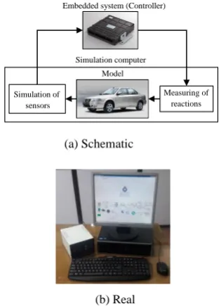
During the rapid prototyping, the real-time system is connected to the real-time hardware. HIL simulation is realized in a form that plant system is running as simulation in computer or in simulator and controller is implemented on an electronic board [11, 12]. After that, the HIL simulated object can be substituted with real object, which represents the comprehensiveness of HIL simulation compared to other tests and simulations performed in the early stages of MBD method [9]. In Figure 3, schematic and real implementation of HIL test is presented.
Figure 3: HIL testing and simulation, a: Schematic, b: Real
Embedded system (Controller)
Simulation computer
Simulation of
sensors
Measuring of
reactions Model
(a) Schematic (b) Real
Embedded system (Controller)
Simulation computer
Simulation of sensors
Measuring of reactions Model
(a) Schematic (b) Real
Figure 1: Model Based Design V-Diagram of a control system
International Journal of Automotive Engineering (IJAE) 2961
3.1. Model of PHEV rule-based control strategy
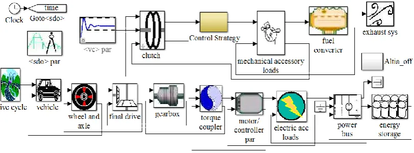
PHEVs, with two power sources, including electric motor and internal combustion engine and a high capacity battery pack can be charged through the power grid. The control strategy determines the share of electric motor and combustion engine in providing required power, and has a significant impact on performance, fuel economy and vehicle efficiency [13-14]. In order to design an energy management strategy and perform HIL testing, the model of vehicle must first be produced [15]. The PHEV model used to develop and verification of implementation of the controller is shown in Figure 4.
The structure of the used rule-based controller is schematically illustrated in figure 5. In this case, the controller determines the share of each power source, according to the requested power and Battery SOC.
3.2. Removing noisy data using data packing method
In Figure 6, the control algorithm and blocks
Figure 5: Schematic of rule-based controller
construction
In this research, using data packing method, the noisy data entered into the electronic board and the computer system are deleted. In this method, in order to detect noise data from other data, all transmitted data in each sample time, should be packed. The created packet contains three sections, include primary data, main data, and end data. Primary data, including three English letters, are chosen arbitrarily. In main data section, data intended for transfers from origin to destination are placed. When main data includes several signals for transmission between the electronic board and the computer system, then the data should be placed in main data section respectively. Final data is the binary summation of primary and main data. In Figure 7, the created data packet to send data to the computer system is shown.
Figure 4: Model of the PHEV
2962 International Journal of Automotive Engineering (IJAE)
Figure 7: Data packing block
Similarly, the data sent to the electronic board is packaged. In the receiver area, the accuracy of the end and primary data is investigated. Figure 8 shows how to verify the accuracy of the end data. The precision of primary data is validated by a predefined function.
Figure 8: Checksum block
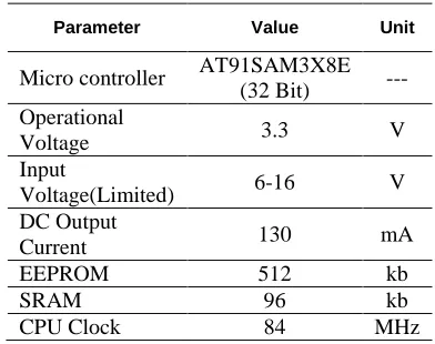
In MBD method, the software code of the controller is generated using the model of controller, and is used for electronic board programming. Specifications of the hardware used for implementation are shown in Table 1.
Table 1: Hardware specifications
Parameter Value Unit
Micro controller AT91SAM3X8E
(32 Bit) ---
Operational
Voltage 3.3 V
Input
Voltage(Limited) 6-16 V
DC Output
Current 130 mA
EEPROM 512 kb
SRAM 96 kb
CPU Clock 84 MHz
Finally, using the developed controller and PHEV models previously mentioned, the verification of implementation is carried out through HIL simulation.
4.
Results and Discussions
In this section, the results of the MBD based hardware implantation of the PHEV control strategy are presented using HIL test. In this research, 115200 bps (bits per second) is considered as baud rate of simulation. In
Figure 6: Control algorithm and blocks
International Journal of Automotive Engineering (IJAE) 2963
is acceptable, which indicates that the selected hardware for controller is suitable for this application. Also, the results of these two tests are highly matched, which indicates the effectiveness of data packing and MBD method.
Figure 9: Motor torque (freq. rate: 100Hz)
Figure 10: Engine torque (freq. rate: 100Hz)
Figure 11: State of charge of battery (freq. rate: 100Hz)
In order to investigate the effects of frequency rate on the noise and delay of transmission signals between the electronic board and computer system, diagram of electric motor torque obtained from HIL simulation with the frequency rate of 1000 Hz is shown in Figure 12. In this condition time delay between MIL and HIL simulation is 0.22S. Also, the engine torque diagram obtained from HIL testing with two frequency rates 100 and 1000 are very close together.
Figure 12: Motor torque (freq. rate: 1000HZ)
2964 International Journal of Automotive Engineering (IJAE)
5.
Conclusion
In this research, PHEV energy management is implemented by applying model-based design method. In order to verify the performance of the implemented control strategy, hardware-in-the-loop (HIL) simulation is performed. The real time simulation has been done on a computer system, with the controller as external hardware. Thus, the time of PHEV control system development is significantly reduced. Furthermore, the results show that by applying MBD method for implementation, controller hardware has acceptable behaviour in comparison with the software simulation, which implies the effectiveness of MBD method. In addition, the results show that data packing method used for data transfer and receive between the electronic board and the computer, is effective in improving the performance of the electronic board.
References
[1] H. He, R. Xiong, K. Zhao, Z. Liu, Energy management strategy research on a hybrid power system by hardware-in-loop experiments, Applied Energy, vol. 112, pp. 1311-1317, 2013.
[2] S. Nabi, M. Balike, J. Allen, K. Rzemien, An overview of hardware-in-the-loop testing systems at Visteon, SAE paper 2004-01-1240, Vol. 5, 2004.
[3] X. Yang, B. Kirby, Q. Zhao, Y. Ma, F. Xu, "Model-based design process for product development of substation IEDS", Proc. IEEE Energycon Conf. Exhib., pp. 968-974, 2012A.
[4] R. Mayyas, S. Kumar, P. Pisu, J. Rios, P. Jethani, Model-based design validation for advanced energy management strategies for electrified hybrid power trains using innovative vehicle hardware in the loop (vhil) approach, Applied Energy, vol. 204, pp. 287-302, 2017.
[5] L. Wang, Y. Zhang, C. Yin, H. Zhang, C. Wang, Hardware-in-the-loop simulation for the
design and verification of the control system of a series–parallel hybrid electric city-bus, Simulation Modelling Practice and Theory, Vol. 25, pp. 148-162, 2012.
[6] V. Lambersky, Model based design and automated code generation from Simulink targeted for TMS570 MCU, Education and Research Conference (EDERC) 2012 5th European DSP, pp. 225-228, 13-14Sept, 201.
[7] J. Luo, K. R. Pattipati, L. Qiao, S. Chigusa, Model-based prognostic techniques applied to a suspension system, Trans. Systems Man and
Cybernetics, vol. 38, pp. 1156-1168, 2003.
[8] M. Ahmadian, Z. Nazari, N. Nakhaee, Z.
Kostic, Model based design and
SDR, DSPenabledRadio 2005. The 2nd IEE/EURASIP Conference on (Ref. No. 2005/11086), pp. 8, Sept 2005.
[9] Ľubica Miková, Michal Kelemen , Ivan Virgala, Tomáš Lipták, Model Based Design of Embedded Systems, Journal of Automation and Control, vol. 5, no. 2, pp. 64-68, 2017.
[10] M Mansour Ahmadian, Nory Nakhaee, and Andrew Nesterov, Rapid Application Development (RAD) and code optimization technique, Global Signal Processing Conference
(GSPx), 2004.
[11] X. Hu, J. Jiang, B. Egardt, D. Cao, Advanced power-source integration in hybrid electric vehicles: Multicriteria optimization approach, IEEE Trans. Ind. Electron., vol. 62, no. 12, pp. 7847-7858, Dec. 2015.
[12] Millo Federico, Zhao Jianning, Rolando Luciano, Cubito Claudio, Fuso Rocco, Optimizing the design of a plug-in hybrid electric vehicle from the early phase: an advanced sizing methodology, Comput-Aid Design and Applications, vol. 12, no. 1, pp. 22– 32, 2015.
[13] M. Bostanian, S. M. Barakati, B. Najjari, and D. M. Kalhori, A Genetic-Fuzzy Control
International Journal of Automotive Engineering (IJAE) 2965
Maghsoodpour, and A. Khodayari, “GPS / INS Integration for Vehicle Navigation based on INS Error Analysis in Kalman Filtering,” vol. 6, no. 4, 2017.