University of New Orleans University of New Orleans
ScholarWorks@UNO
ScholarWorks@UNO
University of New Orleans Theses and
Dissertations Dissertations and Theses
5-16-2008
Implementation of Secure Key Management Techniques in
Implementation of Secure Key Management Techniques in
Wireless Sensor Networks
Wireless Sensor Networks
Noor Ottallah
University of New Orleans
Follow this and additional works at: https://scholarworks.uno.edu/td
Recommended Citation Recommended Citation
Ottallah, Noor, "Implementation of Secure Key Management Techniques in Wireless Sensor Networks" (2008). University of New Orleans Theses and Dissertations. 703.
https://scholarworks.uno.edu/td/703
Implementation of Secure Key Management Techniques in Wireless
Sensor Networks
A Thesis
Submitted to the Graduate Faculty of the University of New Orleans in partial fulfillment of the requirements for the degree of
Masters of Science In
Computer Science Information Assurance
By
Noor J. Ottallah
B.S University of New Orleans, 2005
Acknowledgment
Any project no matter how small or big is never worked on solo. For all the people who
stood by me to make this project happen, I take the time to thank them. I feel greatly privileged
to express thanks to all the people who helped me to complete the project successfully. I would
like to thank Dr. Jing Deng, Professor, mentor, and friend of the Computer Science Department,
University of New Orleans, for giving me the opportunity and infrastructure to work on this
project and for providing his expertise and guidance throughout the duration of the project. Big
thanks to Fareed Qadura director of the I.T operations for extending his support and expertise to
me. I convey my sincere regards to our internal guide Dr Shengru Tu, for providing invaluable
suggestions and guidance at all stages of the project. I also would like to thank Dr. Adlai Depano
for being on my research committee. A Big thank you to all the faculty members of the CSCI
department for teaching me what I know. I would also like to thank the Sermis development
team, at the Technology Park for their respect and support and understanding. With out it I might
have not had time to finish this project.
Last but definitely not least, to my wife Shirouk, your love and your constant
encouragement kept me going when I felt like quitting. I love you and I know you will always be
there for me.
Contents
Abstract... v
Chapter 1 Introduction ... 1
1.1 Communications in WSNs ... 2
1.2 Security issues in WSNs... 4
1.3 Security Requirements for WSNs... 5
1.4 Security Key Issues ... 7
1.5 Key Distribution... 8
1.5.1 Key pre‐distribution ... 8
Chapter 2 System Requirement Specification ... 10
2.1 Hardware Specification ... 11
2.1.1 MPR2400 MICAz Mote... 11
2.1.2 The MTS300 Sensor Boards ... 16
2.2 Software Specifications... 19
2.2.1 TinyOS ... 20
2.2.2 NesC ... 21
2.2.3 TinyDB ... 23
2.3 Software Installation ... 27
2.3.1 Pc Requirements ... 27
2.3.2 Installation of apps on the Nodes ... 36
2.3.3 Connecting the hardware ... 37
2.4 Installing TinyDB application... 40
2.4.1 Starting the TinyDB GUI on the PC... 41
2.4.2 Displaying the Topology... 41
2.4.4 Results being received and charted by TinyDB... 44
2.5 Storing the Results Data in PostgreSQL (Optional) ... 44
Chapter 3 System Implementation ... 47
3.1 Design... 49
3.2 Implementation ... 51
3.2.1 TinyOS changes ... 51
3.2.2 Java Application changes ... 54
3.3 Securing TinyDB+ ... 56
3.4 Changing the Keys in TinyDB+... 57
3.4.1 Key updating using TinySec... 57
3.4.2 Key updating using Over the Air reprogramming ... 58
Chapter 4 Tests and Results... 60
4.1 Connectivity ... 60
4.2 Security... 66
Chapter 5 Conclusion and future work ... 67
References ... 68
Vita ... 71
Abstract
Creating a secure wireless sensor network involves authenticating and encrypting
messages that are sent throughout the network. The communicating nodes must agree on secret
keys in order to be able to encrypt packets. Sensor networks do not have many resources and so,
achieving such key agreements is a difficult matter. Many key agreement schemes like
Diffie-Hellman and public-key based schemes are not suitable for wireless sensor networks.
Pre-distribution of secret keys for all pairs of nodes is not viable due to the large amount of memory
used when the network size is large.
We propose a novel key management system that works with the random key
pre-distribution scheme where deployment knowledge is unknown. We show that our system saves
users from spending substantial resources when deploying networks. We also test the new
system’s memory usage, and security issues. The system and its performance evaluation are
presented in this thesis.
Key Words
Wireless sensor networks, TinyDB, node, secure key, TinyOS, NesC.
Chapter
1
Introduction
Wireless sensor networks are networks of small, battery-powered, memory-constraint
devices named sensor nodes, which have the capability of wireless communication over a
restricted area [1]. Due to memory and power constraints, they need to be well arranged to build
a fully functional network. Environments, where sensor nodes are deployed, can be controlled
(such as home, office, warehouse, forest, etc.) or uncontrolled (such as hostile or disaster areas,
toxic regions, etc.). When the environment is known and under control, deployment may be
achieved manually to establish an infrastructure. However, manual deployments become
infeasible or even impossible as the number of the nodes increases. If the environment is
uncontrolled or the WSN is very large, deployment has to be performed by randomly scattering
the sensor nodes to target area. It may be possible to provide denser sensor deployment at certain
spots, but exact positions of the sensor nodes can not be controlled [2]. Thus, network topology
can not be known precisely prior to deployment. Although topology information can be obtained
by using mobile sensor nodes and self-deployment protocols as proposed in [3], this may not be
possible for a large scale WSN.
To insure the security factor in WSNs we must tackle five challenges [3, 4]:
1. Wireless nature of communication.
2. Resource limitation on sensor nodes.
3. Very large and dense WSNs and lack of a central infrastructure.
4. Unknown network topology prior to deployment.
Many solutions for Network Security for networks that operate under adversarial
conditions depend on the existence of strong and efficient key distribution techniques.
However, it is very difficult, or even impossible in uncontrolled environments, to visit large
number of sensor nodes, and change their setup. Moreover, use of a unary shared key that would
be hard coded into all of the nodes in a WSN is not a good idea because any hostile force can
easily obtain the key. To overcome this problem, sensor nodes have to adapt their environments,
and create or find a secure network by:
1. Use pre-distributed keys or key algorithms,
2. Exchange information with their closest neighbors
3. Exchange information with computationally strong nodes [5].
1.1 Communications in WSNs
Communication in WSNs is much like wireless ad hoc networks. Similarly, WSNs are
ever changing in a way that radio range and network connectivity changes by time. Sensor nodes
die and new sensor nodes may come up in to the network. However, WSNs are more
constrained, denser, and have to deal with redundant information which can be good or bad
depending on the application. WSN architectures are organized in hierarchical and distributed
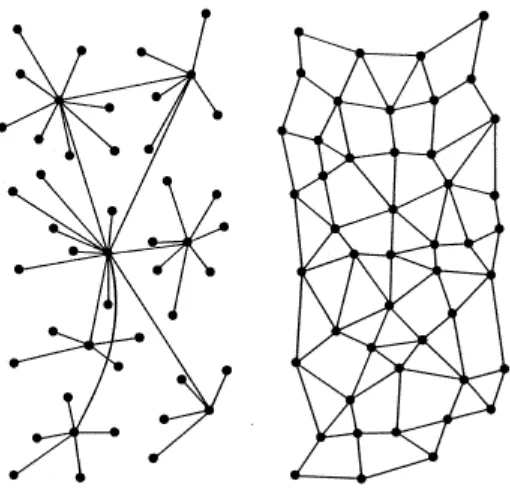
Fig. 1 Network Models: Hierarchical and Distributed Wireless Sensor Networks.
Hierarchical WSNs as shown in Figure 1(left); there is a hierarchy among the nodes based on
their capabilities: base stations or root nodes, cluster heads and sensor nodes. Base stations are
on a higher magnitude of power than sensor nodes and cluster heads. A base station is typically a
gateway to another network, a powerful data processing / storage center, or an access point for
human interface. In some cases the base station is given the responsibility of key distribution.
A Distributed WSNs is shown in Figure 1(right); there is no preset infrastructure, and
network topology is not known prior to deployment. Sensor nodes are usually randomly scattered
all over the target area. Once they are deployed, each sensor node scans its radio coverage area to
figure out its neighbors. Data flow in distributed WSNs is similar to data flow in Hierarchical
1.2 Security issues in WSNs
Hostile forces have better chances at attacking WSNs because of the lack of infrastructure
and lack of a controlled environment. Equipped hackers with powerful computers and
communication devices may access the whole WSN from a remote location which can be
stationed any where around the network. They can gain mobility by using powerful laptops,
batteries and antennas, and move around or within the WSN. Also, adversaries can plant their
own sensor nodes, base stations or cluster heads in uncontrolled environments. They can
compromise, replace or physically damage existing ones. Wirelessly attacking WSNs can help
adversaries to perform different variety of active, passive and stealth type of attacks [5].
●Passive eavesdropping
An unauthorized node will be able to gather data that could include the information of the
network topology, and other information about other authorized nodes which forward or
receive data. Hence, techniques may be needed to hide such information. Eavesdropping is
also a threat to location privacy. Note that passive eavesdropping also allows unauthorized
nodes to discover the exact geographical location of a node by just detecting and calculating
the signal strength.
●Active interference
The major threat from active interference is a denial of service attack caused by blocking the
wireless communication channel. The effects of such attacks depend on the routing protocol
in use, for example, reactive routing protocols may detect a denial of service attack as a link
break. Route maintenance operations, such as, “RTS messages” will cause most protocols to
The content of data that flows with in WSNs can be defined as:
1. Mobile code.
2. Sensor Key readings.
3. Key management.
4. Location information.
In addition to active and passive attacks on key management traffic, adversaries may improve
their capabilities by accessing mobile codes and location information. An adversary can insert a
malicious mobile code which might spread to whole WSN, potentially compromising its
security. It can use the location information to locate critical nodes, capture and read their
security contents [4, 7].
1.3 Security Requirements for WSNs
To provide security, encryption technologies are used to achieve secret communications.
To encrypt the data, a prerequisite is the secret keys should be set up among communicating
sensor nodes. Key management is the process in which keys are created, stored, protected,
transferred, used and destroyed [8]. Keying means the process of achieving keys agreement
among sensor nodes by deriving common secret keys among communicating parties. Pair-wise
keying involves two parties agreeing on a shared session key while group keying is that more
than two parties to set up the communication key [9]. Currently several keying schemes have
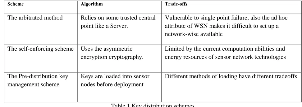
Scheme Algorithm Trade-offs
The arbitrated method Relies on some trusted central
point like a Server.
Vulnerable to single point failure, also the ad hoc attribute of WSN makes it difficult to set up a network-wise available
The self-enforcing scheme Uses the asymmetric encryption cryptography.
Limited by the current computation abilities and energy resources of sensor network technologies
The Pre-distribution key management scheme
Keys are loaded into sensor nodes before deployment
Different methods of loading have different tradeoffs
Table 1 Key distribution schemes
In our research we mainly consider applying the pre distribution key management scheme, in
which keys are loaded into sensor nodes before deployment. WSNs which resemble adhoc and
MANET networks also need to follow general security requirements which are referred to as the
CIAAN [5]:
• Availability: ensuring that service offered by whole WSN, by any part of it, or by a single
sensor node must be available whenever required.
• Authentication: authenticating other nodes, cluster heads, and base stations before
granting a limited resource, or revealing information.
• Integrity: ensuring that message or the entity under consideration is not altered.
• Confidentiality: providing privacy of the wireless communication channels to prevent
eavesdropping.
1.4 Security Key Issues
Key management is a fundamental security issue in sensor networks. It is the basis to
establish the secure communication using cryptographic technologies between sensor nodes in a
sensed area. However, because of the limited resources a sensor has, it is infeasible to use
traditional key management techniques such as public key cryptography or key distribution
center based protocols [14].
A proper key-management service is required to ensure that nodes which are legitimate members
of the network will only be those who are equipped with the necessary keys. The following
shows several needed classifications of key management properties [4, 6, 9, and 15].
• Efficiency: storage, processing and communication limitations must be considered.
• Storage complexity: amount of memory required to store security credentials.
• Processing complexity: amount of processor cycles required to establish a key.
• Scalability: ability to support larger networks, and must be flexible against substantial
increase in the size of the network even after deployment.
• Communication complexity: number of messages exchanged during a key generation
process.
• Resilience: resistance against node capture.
• Key connectivity (probability of key-share): probability that two (or more) sensor nodes
store the same key or keying material. Enough key connectivity must be provided for a
1.5 Key Distribution
Key distribution is an important issue in wireless sensor network (WSN) design. There
are many key distribution schemes out there that are designed to maintain an easy and at the
same time secure communication among sensor nodes. The most accepted method of key
distribution is WSNs is key pre-distribution, where secret keys are placed in sensor nodes before
deployment. When the nodes are deployed over the target area, the secret keys are used to create
the network.
1.5.1 Key pre-distribution
The current key pre-distribution schemes used these days can be classified into four
classes which are detailed with mathematical equations in:
• Pure probabilistic key pre-distribution schemes.
• Polynomial-based key pre-distribution schemes [16].
• Blom’s matrix-based key pre- distribution schemes.
• Deterministic key pre-distribution schemes.
Basically a key pre-distribution scheme has three phases, key distribution, shared key
discovery and path-key establishment [16, 17, and 18]. During these phases, secret keys are
generated, placed in sensor nodes, and each sensor node searches the area in its communication
A secure link is established when two nodes discover one or more common keys, and
communication is done on that link between those two nodes [4]. Afterwards, paths are
established connecting these links, to create a connected graph. The result is a wireless
communication network functioning in its own way.
Each type of scheme has its advantages and application environment. An obvious rule
can be drawn from these proposed schemes is that the location knowledge can be used to
improve the performance of the key management schemes, such as the connectivity, resilience
against nodes capture and memory efficiency [12,19].Our system design will not care if location
knowledge is known or not. It is good to note that most of the key management solutions for
wireless sensor networks are trying to find the better tradeoffs between system security (e.g.,
resilience to node capture) and network connectivity. All of them have weak and strong points.
Chapter
2
System
Requirement
Specification
In order to understand and test how our system works it is crucial to talk about the
components we used to implement the system. Mote kits are a complete set of hardware and
software that include programmable sensor nodes, sensor boards, programming boards, cables,
batteries, cases, and all the software needed to program the nodes.
To use the mote kit and start programming the nodes, certain programs need to be
installed and specific procedures need to be followed. This can be very difficult to do as there is
no unified instruction set that tells the user how to do it. This results in wasted time, frustration
and quitting. The learning curve is very hard and it is almost best that a user has previous
knowledge of UNIX commands, java compiling as well as some knowledge of C language.
This chapter will act as a full detailed instruction tutorial on how to set up the hardware
and set up the software needed for a researcher to start programming for wireless nodes. It will
also attempt to try to give a full description of all the components and software used along with
plenty of figures and visual aids. The information here has been compiled from many sources as
well as from our experiments in the lab. We will be using the MICAZ-MOTE 2400CA kit from
Cross-Bow Technologies [20].
2.1 Hardware Specification
When you open the box you will need to identify all the components. The kits come with
the following:
• 7 MICAz wireless nodes each with 2 AA batteries.
• 3 MTS300 Sensor Boards (Light, Temperature, Acoustic, and Sounder).
• 1 MIB510 Programming and Serial Interface Board.
• Mote-Test Software CD.
• Tiny OS Getting Started Guide PDF.
• 1 MIB600 programming network Interface board with power adaptor.
• 1 interface board to connect other electronic devices to the nodes.
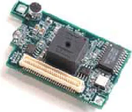
2.1.1 MPR2400 MICAz Mote
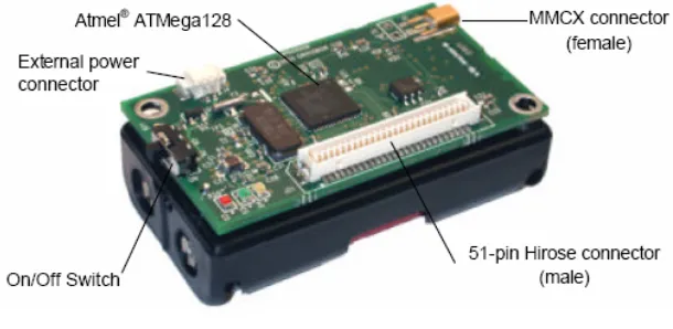
Figure 2 MICAZ MPR2400
1. IEEE 802.15.4/ZigBee compliant RF transceiver. 2. 2.4 to 2.4835 GHz, a globally compatible ISM band.
3. Direct sequence spread spectrum radio which is resistant to RF interference and provides inherent data security.
4. 250 kbps data rate.
5. Runs Tiny OS 1.1.7 and higher, including Crossbow’s reliable mesh networking stack software modules.
6. Plug and play with all of Crossbow’s sensor boards, data acquisition boards, gateways, and software.
7. It has an Atmel processor, ATMega128L.
8. It has an Atmel Nonvolatile memory of 512KB flash, capable to store up to 100,000 measurements.
9. The radio Transceiver used is the Chipcon CC2420. The board also offer enhanced processor capabilities, including a boot-loader that allows for over air reprogramming.
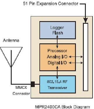
The following table shows some extra features of the MPR2400 also all the information here can also be obtained from Cross-Bow technologies:
Figure 4 – Features of MICAZ
2.1.1.1
Powering
the
Mote
The MPR2400 is powered by two AA batteries; however any battery combination (AAA,
C, D, etc) can be used as long as that the output is between 2.7-3.3VDC. Battery life will vary
depending on the mote utilization and the battery size used .The battery life usually varies
between 1.45 and 17.35 months. The MICAz can also be externally be powered using any wall
2.1.1.2
Radio/Antenna
Considerations
The MICAz’s CC2420 radio can be tuned within the IEEE 802.15.4 channels that are
numbered from 11 (2.405 GHz) to 26 (2.480 GHz) each separated by 5 MHz. The channel can be
selected at run-time with the TOS CC2420Radio library call CC2420Control Tune Preset
(uint8_t chnl) which is part of the TinyOS folder. By default channel 11 (2480 MHz) is selected.
RF transmission power is programmable from 0 dBm (1 mW) to –25dBm. Lower
transmission power can be advantageous by reducing interference and dropping radio power
consumption from 17.5 mA at full power to 8.5 mA at lowest power. RF transmit-ion power is
controlled using the TOS CC2420Radio library call CC2420Control. The Tiny OS component
VoltageM.nc can be wired into an application to provide this measurement capability. The
reserved keyword TOS_ADC_VOLTAGE_PORT is mapped to ADC Channel 30 in the MICAz.
2.1.1.3
Data
Logger
The MICAZ mote also features a 4-Mbit serial flash for storing data, measurements, and
other user-defined information. Tiny OS supports a micro file system that runs on top of this
flash/data logger component. The serial flash device supports over 100,000 measurements
readings. The MICAZ also has a 64-bit serial ID chip.
2.1.1.4
Battery
Voltage
Monitor
Since the eight-channel, Atmega128 ADC uses the battery voltage as a full scale
reference, the ADC full scale voltage value changes as the battery voltage changes. In order to
calibrate the battery voltage, a precision external voltage reference is required. The MICAZ uses
2.1.1.5
The
MIB510
Programming
and
Serial
Interface
Board
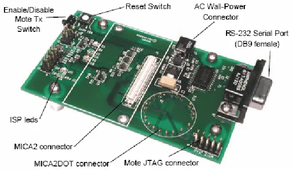
The MIB510 interface board is a multipurpose interface board used with MICAz and
MICA2DOT family of products since it has connectors for both MICAz and MICA2DOT. It
supplies power the device through an external power adapter option, and provides an interface
for a RS-232 mote serial port and reprogramming port.
Figure 5 MIB510 programmer
2.1.1.6
In
System
Processor
The MIB510 has an on-board in-system processor (ISP) to program the motes. The Code
is downloaded to the ISP, over the serial port, and the ISP programs the code into the mote. The
ISP and mote share the same serial port. The ISP runs at a fixed baud rate of 115Kbaud. The
ISP continually monitors incoming serial packets for a special multi-byte pattern. Once this
pattern is detected, it disables the mote’s serial Rx and Tx, and then takes control of the serial
port. The ISP processor has two LEDs, ‘SP PWR’ (green) and ISP (red). SP PWR is used to
indicate the power state of the MIB510 (see below). If the ISP led is on, the MIB510 has control
2.1.1.7
Power
The MIB510 has an on-board regulator that will accept 5 to 7 VDC, and supply a
regulated 3V to the MICAz. The MIB510 is delivered with a wall power supply. There is a
built-in low voltage monitor that disables reprogramming if the power supply voltage is
dangerously low. When the proper programming voltage exists the ISP PWR led is on. If the
voltage goes below 2.9 V, the ISP PWR led will blink and disable the mote from any code
downloads. If the voltage is too low to power the ISP then the ISP PWR led will be off. Things
to remember:
• When programming a MICAZ with the MIB510, turn off the battery switch. The MICAZ
does not have switching diodes to switch between external and battery power.
• The RST MOTE switch resets both the ISP and mote processors. RST resets the ISP;
after the ISP powers-up it resets the mote’s processor.
2.1.2 The MTS300 Sensor Boards
The MTS300CA are sensor boards with a variety of sensing capabilities. These varieties
can be used in developing sensor networks for a variety of applications including movement and
acoustic (sound), low-performance seismic sensing, vehicle detection, ranging, robotics, and
other applications. The MTS300 Sensor Board features:
• Light
• Temperature
• Microphone, Sounder
• Tone Detection Circuit
2.1.2.1
Light
The light sensor, CL94L, is a simple CdSe photocell, manufactured by Clairex. The
maximum sensitivity of the photocell is at the light wavelength of 690nm. In order to use the
light sensor, the digital control signal, PW1, must be turned on and the output of the sensor is
connected to the analog-digital converter channel 1 (ADC1). When the sensor is exposed to
light, the typical on resistance is 2Kohm and the nominal circuit output is near VCC or full-scale.
2.1.2.2
Temperature
The temperature sensor is a surface mount thermostat made by Panasonic It is configured
in a simple voltage divider circuit with a nominal mid-scale reading at 25oC. The output of the
temperature sensor circuit is available at ADC1. Since the light and temperature sensor share the
same A/D converter channel (ADC1). Only turn one sensor on at a time, or the reading at ADC1
2.1.2.3
Microphone
The microphone circuit has two principal uses. The first use is for acoustic ranging. The
second use is for general acoustic recording and measurement.
The basic circuit consists of a pre-amplifier (U1A-1), second-stage amplified with a
digital-pot control (U1A, PT2). Audio files have been recorded into the Logger Flash memory of
MICAZ Motes for later download and entertainment (or analysis). The second stage output
(mic_out) is routed through an active filter (U2) and then into a tone detector (TD1). The LM567
CMOS Tone Detector IC actually turns the analog microphone signal into a digital high or low
level output at INT3 when a 4 KHz tone is present .
The Sounder circuit on the sensor board can generate this tone. A novel application of the
sounder and tone detector is acoustic ranging. In this application, a mote pulses the sounder and
sends an RF packet via radio at the same time. A second mote listens for the RF packet and notes
the time of arrival by resetting a timer/counter on its processor. It then increments a counter until
the tone detector detects the sounder. The counter value is the Time-of-Flight of the sound wave
between the two motes.
The Time-of-Flight value can be converted into an approximate distance between motes. Using
groups of Motes with Sounders and Microphones, a crude localization and positioning system
2.1.2.4
Sounder
The sounder is a simple 4 kHz fixed frequency piezoelectric resonator. The drive and
frequency control circuitry is built into the sounder. The only signal required to turn the sounder
on and off, is Sounder_Power. Sounder_Power is controlled through the power control switch
(P1) and is set by the hardware line PW2.
2.1.2.5
Turning
Sensors
On
and
Off
All of the sensors have a power control circuit. The standard condition for the sensor is to
be off. This design helps minimize power consumption by the sensor board. In order to turn
sensors on; control signals are issued to the power switches.
2.2 Software Specifications
TinyOS is a free and open source component-based operating system and platform
targeting wireless sensor networks (WSNs). TinyOS is an embedded operating system written in
the nesC programming language as a set of cooperating tasks and processes [21]. TinyOS started
as collaboration between the University of California and in co-operation with Intel Research. It
has since grown to be an international consortium, the TinyOS Alliance. We build our system
around the following software components:
• TinyOS supports Crossbow Mica motes, MICAz motes and Mica2Dot motes and a few
other wireless sensor devices. TinyOS is embedded in Crossbow motes and therefore we
• NesC (network embedded systems C) is the Programming language used to develop
software on TinyOS. NesC is an extension to C that involves the necessary structures and
concepts to support event-driven execution of TinyOS.
• TinyDB: TinyDB [21, 22] which is a query processing system for extracting information
from a network of TinyOS sensors. In addition to the mote software, TinyDB provides a
PC interface written in Java. The TinyDB software is to be modified to incorporate the
Key management algorithm.
2.2.1 TinyOS
TinyOS is an open-source operating system designed for wireless embedded sensor
networks. It is made up from a component-based architecture which enables rapid innovation and
implementation while minimizing code size as required by the severe memory limitation inherent
in sensor networks [21]TinyOS’s component library includes network protocols, distributed
services, sensor drivers, and data acquisition tools - which can be used as-is or be further refined
for a custom application. TinyOS’s event-driven execution model enables fine-grained power
management yet allows the scheduling flexibility made necessary by the unpredictable nature of
wireless communication and physical world interfaces. TinyOS has been ported to over a dozen
platforms and numerous sensor boards. A wide community uses it in simulation to develop and
test various algorithms and protocols [21, 23].
Everything in a TinyOS application is static:
• No Dynamic Memory (no malloc ())
• No Function Pointers
This means that just about everything is known at compile time by the NesC compiler. This
allows the compiler to perform global compile time analysis to detect data race conditions, and
where function in lining will improve performance. This relieves the developer of these burdens
and hence development is made easier and the systems robustness is improved. The memory
map of a TinyOS application is similar to the structure of an executable image on the Unix OS.
The MICAz generation of Motes which we use in our project consists of 128k of program flash
and 4k of SRAM. The memory image is as follows:
In the 128K Program Flash
•”text” section holds the executable Code
•”data” section holds the program Constants
In the 4K SRAM (flash)
•”bss” section holds the variables
• The rest of the bss is free space – which means it is fixed because the lack of dynamic memory.
• stack - grows down in the free space
2.2.2 NesC
NesC is an extension to the C programming language designed to embody the structuring
concepts and execution model of TinyOS .TinyOS is an event-driven operating system designed
for sensor network nodes that have very limited resources (e.g., 8K bytes of program memory,
The basic concepts behind NesC are:
• Separation of construction and composition: programs are built out of components, which are
assembled (”wired”) to form whole programs. Components have internal concurrency in the
form of tasks. Threads of control may pass into a component through its interfaces. These
threads are rooted either in a task or a hardware interrupt.
• Specification of component behavior in terms of set of interfaces: Interfaces may be provided
or used by components. The provided interfaces are intended to represent the functionality that
the component provides to its user; the used interfaces represent the functionality the component
needs to perform its job.
• Interfaces are bidirectional: they specify a set of functions to be implemented by the interface’s
provider (commands) and a set to be implemented by the interface’s user (events). This allows a
single interface to represent a complex interaction between components (e.g., registration of
interest in some event, followed by a callback when that event happens). This is critical because
all lengthy commands in TinyOS (e.g. send packet) are non-blocking; their completion is
signaled through an event (send done). By specifying interfaces, a component cannot call the
send command unless it provides an implementation of the send-Done event.
• Typically commands call downwards, i.e., from application components to those closer to the
hardware, while events call upwards. Certain primitive events are bound to hardware interrupts.
• Components are statically linked to each other via their interfaces. This increases runtime
efficiency, encourages robust design, and allows for better static analysis of programs.
• NesC is designed under the expectation that code will be generated by whole program
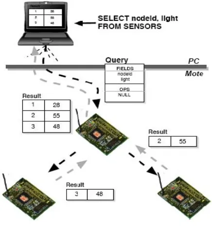
2.2.3 TinyDB
TinyDB [22, 24] is a query processing system for extracting information from a network
of TinyOS sensors. TinyDB does not require writing embedded C code for sensors like TinyOS.
Instead, TinyDB provides a simple, SQL-like interface to specify the data, along with additional
parameters. It functions like posing queries against a traditional database. Given a query
specifying data interests, TinyDB collects that data from motes in the environment, filters it,
aggregates it together, and routes it out to a PC or a Base Station. TinyDB does this via
power-efficient in-network processing algorithms. To use TinyDB, its TinyOS components are installed
onto each mote in the sensor network. TinyDB provides a simple Java API for writing PC
applications that query and extract data from the network; it also comes with a simple graphical
query-builder and result display that uses the API. The primary goal of TinyDB is to make work
as a programmer significantly easier, and allow data-driven applications to be developed and
deployed much more quickly than what is currently possible. TinyDB frees from the burden of
writing low-level code for sensor devices, including the (very tricky) sensor network interfaces.
Some of the features of TinyDB include:
• Metadata Management: TinyDB provides a metadata catalog to describe the kinds of sensor
readings that are available in the sensor network.
• High Level Queries: TinyDB uses a declarative query language that describes the data wanted,
without requiring saying how to get it. This makes it easier to write applications, and helps
guarantee that the applications continue to run efficiently as the sensor network changes.
• Network Topology: TinyDB manages the underlying radio network by tracking neighbors,
• Multiple Queries: TinyDB allows multiple queries to be run on the same set of motes at the
same time. Queries can have different sample rates and access different sensor types, and
TinyDB efficiently shares work between queries when possible.
• Incremental Deployment via Query Sharing: To expand the TinyDB sensor network, it is only
required to simply download the standard TinyDB code to new motes, and TinyDB does the rest.
TinyDB motes share queries with each other; when a mote hears a network message for a query
that it is not yet running, it automatically asks the sender of that data for a copy of the query, and
begins running it. No programming or configuration of the new motes is required beyond
installing TinyDB.
2.2.3.1
TinyDB
System
Overview
Figure 7 TinyDB
This section provides a high level overview of the architecture of the TinyDB software. It
We begin with a short description of a typical use-case for TinyDB. Imagine that John wants to
find an unused conference room in his sensor equipped building, and that an application to
perform this task has not already been built. The motes in John’s building have a sensor board
with light sensors and microphones and have been programmed with a room number. John
decides that his application should declare a room in-use when the average light reading of all
the sensors in a room is above a certain value. John wants his application to refresh this
occupancy information every 10 minutes. Without TinyDB, John would have to write a couple
hundred lines of custom C code to collect information from all the motes in a room, coordinate
the readings across sensors, aggregate these readings together to compute the average light and
volume, and then forward that information from within the sensor network to the PC where the
application is running.
He would then have to download his compiled program to each of the motes in the room.
Instead, if the motes in John’s building are running TinyDB, he can simply compose the
following SQL query to identify the rooms that are currently in-use:
SELECT roomno, AVG (light), AVG (volume)
FROM sensors
GROUP BY roomno
HAVING AVG (light) >20
EPOCH DURATION 5min
TinyDB translates this query into an efficient execution plan which delivers the set of occupied
rooms every 5 minutes. John simply inputs this query into a GUI - he writes no C code and does
and reporting data, and many other hard to do actions with sensor-network programming. The
system can be broadly classified into two subsystems: Sensor Network Software: This is the
heart of TinyDB, although most users of the system should never have to modify this code. It
runs on each mote in the network, and consists of several major pieces [24]:
• Sensor Catalog and Schema Manager: The catalog is responsible for tracking the set of
attributes, or types of readings (e.g. light, sound, voltage) and properties (e.g. network parent,
node ID) available on each sensor. In general, this list is not identical for each sensor: networks
may consist of heterogeneous collections of devices, and may be able to report different
properties.
• Query Processor: The main component of TinyDB consists of a small query processor. The
query processor uses the catalog the fetch the values of local attributes, receives sensor readings
from neighboring nodes over the radio, combines and aggregates these values together, filters out
undesired data, and outputs values to parents.
• Memory Manager: TinyDB extends TinyOS with a small, handle-based dynamic memory
manager
• Network Topology Manager: TinyDB manages the connectivity of motes in the network, to
efficiently route data and query sub-results through the network.
• Java-based Client Interface: A network of TinyDB motes is accessed from a connected PC
through the TinyDB client interface, which consists of a set of Java classes and applications.
These classes are all stored in the tinyos- 1.x/tools/java/tinyos/tinydb package in the source tree.
Major classes include:
• A network interface class that allows applications to inject queries and listen for results
• A class to receive and parse query results
• A class to extract information about the attributes and capabilities of devices
• A GUI to construct queries
• A graph and table GUI to display individual sensor results
• A GUI to visualize dynamic network topologies
• An application that uses queries as an interface on top of a network of sensors.
2.3 Software Installation
This section will describes how to implement a Wireless Sensor Network using MICAz
Motes loaded with TinyOS and TinyDB. We assume that the motes are not yet programmed with
TinyDB. Once finished, the user will be able to use a Windows PC to insert SQL-like queries
into the Sensor Network, perform some measurements and have the results returned to the base
PC.
TinyOS is extremely sensitive to hardware and software configurations. The system has
many dependencies that rely on specific versions of software components. Using older or newer
versions of a particular component may cause incompatibilities resulting in the system refusing
to build and execute [20, 22, and 23]. The kit includes a CD-ROM that contains all of the
necessary software components to build a system from the ground up and allows you to perform
some simple experiments.
2.3.1 Pc Requirements
We recommend running the software on a Windows XP services pack 2 boxes with a
The software will run at lower specs but we found that it operated much better with the previous
specs if not higher. Of course, the more resources a Pc will have the better.
TinyOS and TinyDB have three major components.
1. A java based Graphical User Interface (GUI) that runs on a MS Windows.
2. A C flashed firmware that runs as an embedded application on the mote.
3. A software development environment that allows creation of the previous.
The hardware used in this guide was a selection of MICAZ Motes from Crossbow Technology
Inc. The Motes were model MPR2400CA using the CC2420 2.4 GHz data radio. The sensor
boards used were the MTS300CA which enables the mote to measure temperature, sound and
light in addition to the battery voltage (used to power the Motes). The base station interface unit
that we use to program the motes, model MIB510CA, is RS232 based and serves two main
purposes:
(1) It allows the user to reprogram any mote by plugging the mote directly into the base.
(2) It operates as part of the root node interface giving the PC a data conduit onto the radio based
sensor network.
For those who might use laptops a word of caution; The MIB510CA interface must be connected
to the PC via RS232 which is a DE9 port (serial). Many modern laptops are being produced
without this port. If your laptop does not have such a port, you must use a special cable called a
“USB to Serial Adapter” which can be found at almost any computer hardware store (see figure
Figure 8 (DE9 port and USB cable
2.3.1.1
Step
one
installing
UCB
TinyOS
1.1.11
The first step is to install the base system of TinyOS. All of the required files can be
found on the included CDROM or downloaded from the following website:
http://www.tinyos.net/dist-1.1.0/tinyos/windows/ .
We recommend downloading the installer from the website because the CDROM has an older
version particularly TinyOS version 1.1.0-1is.The installer from the web page is a newer version
called tinyos-1.1.11-3is. Please be aware that TinyOS v2.0 is out. The new version has more
features but it still lacks to be a stable version. We will use 1.1.11.3is version because it is much
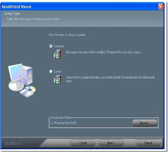
more stable and plenty of support for it can be found online. Double click on the installer and
please be patient while the system performs some system checks that can take up to 1 minute to
complete; eventually the splash screen pictured above will appear. Unless you are an expert,
pick complete when asked what type of installation you want.
Depending on the speed of the machine and whether or not anti-virus software is installed, it can
take up to 15 minutes for the Installer to complete all steps. Please be aware that Anti-virus
software will dramatically slow down the installation as it scans thousands of files, many of them
Figure 9 TinyOS set up splash screen
2.3.1.2
Step
2
Post
Installation
procedures
After the installer finishes you should now have a Windows Program Group called
Cygwin along with a desk top short cut. Cygwin is free software that provides a Unix-like
environment and software tool set to users of any modern version of MS-Windows for x86 CPUs
(95/98/NT/2000/ME/XP). Cygwin consists of a UNIX system call emulation library,
cygwin1.dll, together with a vast set of GNU and other free software applications organized into a large number of optional packages. Among these packages are high-quality compilers and
other software development tools, a complete X11 development toolkit, GNU emacs, TeX and
LaTeX, OpenSSH (client and server), and much more, including everything needed to compile
and use PhysioToolkit software under MS-Windows[21].
Start the ‘Cygwin bash shell’ which will give you a Unix-like environment under Windows.
If you do not receive an error, skip down to the next section and go directly to ‘Step 3 Updating
be printed complaining about some missing security files. Not every installation of TinyOS will
receive the error pictured below, it will depend on what networking protocols are configured into
the PC used and if the users are authenticating against a network server (such as Microsoft
Active Directory). As suggested by the error message pictured below, run the following two
commands:
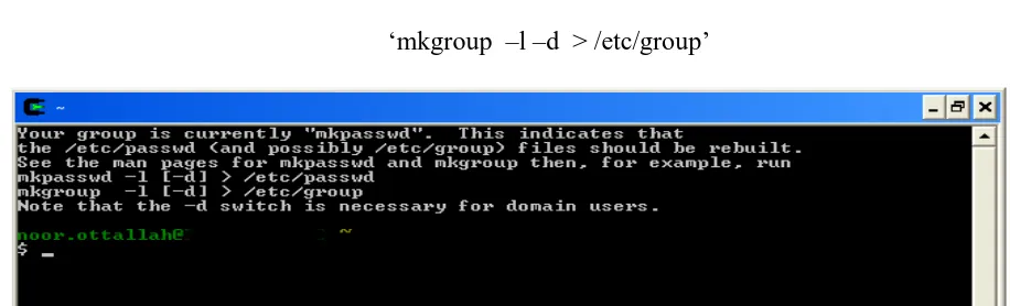
‘mkpasswd –l –d > /etc/passwd ‘
‘mkgroup –l –d > /etc/group’
Figure 10 password error
After fixing the errors, close the shell and open a new one. A new different set of messages will
pop up. The output should look similar to the figure below. Once again you should exit the shell.
You have completed the initial installation of the base software.
2.3.1.3
Step
3
Updating
to
TinyOS
1.1.15
cvs
build
(optional)
Now that TinyOS 1.1.11 is installed, the system should be immediately upgraded to
version 1.1.15. Open a new Cygwin shell window. You must change the working directory to
the same directory that contains the updated RPM file. RPM is an abbreviation that stands for
RPM Package Manager. RPM is also the name of a program that enables the installation,
upgrading and removal of packages. TinyOS is updated through RPMs which you download
from the website or copy from the installation CD. We recommend getting the latest version off
the TinyOS website. If you use the CD option then you will need to mount the drive and access
the folder. To change the working directory to the software directory which in our case, the
CDROM was Windows drive F: which was mounted as ‘/cygdrive/f’ we enter the following:
‘cd /cygdrive/f/software’
We then install the updated system package by entering the following command:
‘rpm --force -ivh --ignoreos *.rpm’
If you download the package from the web you only need to change the working directory to the
folder where the RPM was downloaded and basically run the previous command.
2.3.1.4
Step
4
Checking
the
TOS
Installation
and
CLASSPATH
To ensure that the system is now configured properly and has all the packages and
libraries, the TinyOS distribution includes a program that will verify the configuration of your
machine and will report back if any errors are found. The test must finish without any errors. Do
To test your software configuration, start a ‘Cygwin shell’ and type the following command:
‘toscheck’
Most likely an error complaining about the CLASSPATH will pop up on the screen.. The
CLASSPATH error is caused by a configuration issue with the java environment and will look
similar to the screen shot pictured below.
Figure 12 CLASSPATH error
To fix this problem, a configuration file needs to be open to make a few needed changes. Open
any preferred editor and edit the file named ‘javapath’ located at
‘/opt/tinyos-1.x/tools/java/javapath’
Browse down to line 41 in the file where it shows this:
unshift @add, ".";
You should change it to this:
#unshift @add, ".";
Browse down to lines 57 & 60 where they show this:
print "$addpath;$oldpath\n";
You should change it to this:
print "$addpath\n";
You should change it to be this:
print "$addpath;.\n";
After making the necessary edits to the file, save and exit the shell. Open a new shell and re-run
the toscheck. It should now complete without errors.
2.3.1.5
Step
5
Building
the
java
tools
We need to run a couple of scripts that will tell the system to grab all the information
needed to compile java classes .To start, type in the commands below and wait for them to
complete this will compile the java tools on your system:
cd /opt/tinyos-1.x/tools/java make
cd /opt/tinyos-1.x/tools/java/jni make install
2.3.1.6
Step
6
Running
the
TinyDB
GUI
for
the
PC
The TinyOS and TinyDB system is comprised of 2 major components. One part of the
system runs as a java application on the ROOT PC providing the menus and graphing
environment; the other part of the system runs as compiled C code on the motes themselves. To
compile the java GUI for the PC, type the following commands:
‘ cd /opt/tinyos-1.x/tools/java/net/tinyos/tinydb/ make’
The system might take a while to finish depending on the speed of the machine during which a
lot of activity will show on the screen. If at the end you see an error it will most likely be because
1-A java compile error; you are not in the right directory to compile from.
2- Javax not found. This is more likely to happen please check the env PATH and make sure the
system has the right java path included. There is a java.exe in the Windows folder that Cygwin
looks at first. Either delete it from the path or add the correct path of the real java path in front of
it. See the figure below:
Figure 13 Java path
The following commands will start the TinyDB GUI on the PC:
cd /opt/tinyos-1.x/tools/java
java net.tinyos.tinydb.TinyDBMain
Please be aware of the following:
1- The commands listed above are case sensitive. They must be entered exactly as shown
otherwise a ‘java.lang.NoClassDefFoundError’ message will be displayed and the system will
refuse to start.
As an example, on one particular machine, Windows XP assigned COM3 to the device.
The reference from COM1 had to be changed to COM3 for the hardware to talk to the machine
and display results. The filename that required modification was:
‘/opt/tinyos-1.x/tools/java/net/tinyos/tinydb/tinydb.conf’
Line 28 used to have this:
comm.string:serial@COM1$57600
We changed line 28 now has this:
comm.string:serial@COM3$57600
After the modification was completed, java was able to start TinyDB without difficulty.
2.3.2 Installation of apps on the Nodes
This section of the document will describe the steps required to setup, test and program
the MICAz hardware with the appropriate codes. The MICAz platform has a single slide switch.
It is the power switch for the batteries. We mentioned earlier that it is very important to make
sure the switch is in the off position. This will prevent the mote from burning out. With that
done, it is unnecessary to remove the batteries if you ensure that the slide switch is always in the
OFF position whenever the mote is plugged into the MIB510CA programmer by connecting the
daughter port of the mote into the daughter port of the MIB510CA. There is no wrong way to
plug them both together where one side is female and the other is male. The programmer has a
single slide switch that affects how data is sent on the serial com port. It must be in the OFF
Figure 14 On switch on mote and programmer
To test the hardware and get some sensor results we need to do the following:
1. Connect the hardware
2. Compile and load a program onto the MICAz
3. Run an application on the PC that communicates with the MICAz
2.3.3 Connecting the hardware
To set up the hardware please insure the following steps are done:
1- You must be connected to the PC with a serial cable or USB cable.
2- We will assume in this guide you are connected to COM1.
3- You must plug a MICAz into the MIB510CA programmer.
4- A sensor-board is not required for this test.
5- The programmer must be powered via a wall adapter
Figure 15 Complete setup
2.3.3.1
Installing
a
simple
app
‘MicaHWVerify’
Open a ‘Cygwin bash shell’ and type the following commands:
‘cd /opt/tinyos-1.x/apps/MicaHWVerify make micaz’
At this point you now have a custom MICAz compatible program ready to be programmed into
the mote. The previous step created an application ready for transferring into the MICAz. To
write the firmware image to the MICAz chip, type the following command:
‘make micaz reinstall mib510,/dev/ttyS0’
Please be aware again that the above command is case sensitive. Also, be aware of the COM port
the hardware is connected to:
/dev/ttyS0 = com1 /dev/ttyS1=com2 /dev/ttyS2=com3 /dev/ttyS3=com4
The screen will show some info about the programmer chip and if all goes well a message with
the word ‘fuse’x09 or similar will show. You have successfully uploaded the image to the mote.
Next, you will attempt to communicate with the MICAz. To create the PC test program, type the
following command:
To run the program and display a small report, type the following command:
‘MOTECOM=serial@COM1:micaz java hardware_check’
If all goes well, you should see a small report that displays the Node Serial ID (Figure 16)
Figure 16 Hardware test
2.3.3.2
Testing
the
radio
functionality
This test requires two MICAz nodes. One unit will serve as the root node and the second
node will be used as the remote node. During the test, the 2 nodes will communicate with each
via the radio link.
Node #1:
• Take one of the nodes that has passed the ‘Hardware Comms Check’, install
batteries and slide the switch to ON.
• The lights on the MICAz will start to blink, the node is now active!
Node #0:
To compile and load the base station software onto the MICAz, type the following commands:
‘cd /opt/tinyos-1.x/apps/TOSBase make micaz’
‘make micaz reinstall mib510,/dev/ttyS0’
Re-run the ‘Hardware Comms Check’
‘cd /opt/tinyos-1.x/apps/MicaHWVerify’
‘MOTECOM=serial@COM1:micaz java hardware_check’
The Node Serial ID report will be displayed. Notice that the ID of the remote node was
displayed, not the Node ID of the MICAz plugged directly into the base station. The base station
acted as a data conduit passing the serial data onto the radio network; the remote node saw the
data on the RF interface and responded. TinyOS ships with plenty of already made apps which
are located under: ‘/opt/tinyos-1.x/apps/’. Feel free to look at them all as some might come in
handy.
2.4 Installing TinyDB application
Each MICAz must be programmed with a unique copy of the TinyDB software. One
node is called the ROOT Node and during normal operation is always connected directly to the
base station (MIB510CA programmer board). The Node ID of the ROOT Node is always zero.
All other nodes must have a unique non-zero Node ID. The following steps will compile and
install TinyDB on each MICAz node.
1. Change the working directory to the TinyDB directory:
‘cd /opt/tinyos-1.x/apps/TinyDBApp’
2. Compile and install a custom version of TinyDB for the ROOT node (Node#0)
3. Remove the ROOT Node and connect one of your remote nodes. The following
command sets the Node ID to “1” and programs the MICAz node:
‘make micaz reinstall.1 mib510,/dev/ttyS0’
Repeat Step #3 until all MICAz nodes have been programmed. Remember to increment the Node
ID giving each node a unique number. You are now ready to run the TinyDB application on the
motes and PC.
2.4.1 Starting the TinyDB GUI on the PC
The following commands will start the TinyDB GUI on the PC:
‘cd /opt/tinyos-1.x/tools/java’
‘java net.tinyos.tinydb.TinyDBMain’
If the system refuses to start, refer to step 6 in this document for more information.
2.4.2 Displaying the Topology
The first test of the Sensor Network is to determine if indeed you have a network. When
you start the TinyDB GUI, a screen similar to the picture below will appear. Clicking on the
[Display Topology] button causes the system to insert a query into the network that causes all
nodes to respond. Their responses prove that each node is connected and alive. Have patience
when you attempt to display the topology. It usually takes about 4-30 seconds to see some
Figure 17 TinyDB main pages
The ‘Sensor Network Topology’ screen pictured below is a graphical representation of the layout
of the sensor network. It does not how ever reflect the actual locations of the sensors. The ‘Light’
attribute is used to provide a visual indication of the attributes value. Node 0 is the ROOT Node
and was plugged directly into the base station interface. All other nodes were scattered around
three adjoining offices. The office containing Node#4 had the lights turned off (the room was
dark) and the graph clearly shows a low value for that attribute.
Node#2 was on the floor behind a desk in a shadow; the graph shows a darker (but not dark)
2.4.3 Simple Queries
The strength of the TinyDB GUI is the ease in which the user can inject queries into the
Sensor Network and have the results returned and displayed on the base station PC. Pictured
below is the main screen of TinyDB. To start a query, scroll through the list of available
attributes in box #1. Note that although the list contains all supported attributes, not all nodes
will have the sensors installed to perform that measurement. Make sure you do not try to read
from something that does not exist. When you double-click on an attribute in box #1, the
attribute will appear in the listing in box #2 as well as a SQL-like query will be constructed in
box #3. If you have clicked on something accidentally, double-click on the attribute in box #2 to
remove it from the list. When you have selected all of your desired attributes, click on #4 [Send
Query] to start the querying of the network.
Figure 19 GUI sections
Once the query has been injected in the Sensor Network, the nodes will perform readings and
real-2.4.4 Results being received and charted by TinyDB
The above graph represents the plot of light from 3 nodes over a period of 2,490 samples.
Have patience when you send a new query into the network. It can take over a minute for the
query to be encoded, and transmitted to all the nodes for the first response to migrate through the
network back to the base station PC. Once the results start to arrive, they will do so at the
expected rate without delay.
Figure 20 Graph actions
The TinyDB GUI provides a graphing interface but it is not the best method of displaying the
results from multiple attributes. The best way is to collect the data and read into Microsoft Excel
and create a graph.
2.5 Storing the Results Data in PostgreSQL (Optional)
When TinyDB receives results from the Sensor Network, the data is stored and displayed
within the TinyDB GUI as a spreadsheet. Although this is adequate for quick adhoc queries, it
PostgreSQL is an open source project offered as a free download from
http://www.postgresql.org/. PostgreSQL is available on a wide variety of platforms including but
not limited to Windows, Macintosh/OSX and Linux. It is suggested that the above website is
used to download and install the software on the server platform of your choice. If you decide to
use the Windows version of PostgreSQL, a full-screen graphical interface is provided in addition
to the command line tools.
Figure 21 PostgreSQL
To setup PostgreSQL you need to do the following:
1-TinyDB requires a database to be created called ‘tinydb’.
2-A username called ‘tele’ must be created and requires permission to access ‘tinydb’.
3-The PostgreSQL command to create the table is:
‘create table queries (query_table varchar(10), query_time timestamp, query_string varchar(500));’
4-The TinyDB configuration file must be edited to reflect the username/password and location
The configuration file can be found in the following location:
/opt/tinyos-1.x/tools/java/net/tinyos/tinydb/tinydb.conf
Postgres server settings:
• postgres-user:tele
• postgres-passwd:tiny
• postgres-db:task
• postgres-host:localhost
Once the changes have been made to reflect the true location and attributes of the PostgreSQL
database, you will be able to use the [Log to Database] option in TinyDB.
Chapter
3
System
Implementation
Until now there has never been an effort to create a complete system that records sensor
readings from the surroundings and at the same time be able to manage security keys that nodes
use to establish secure connections. We imagined a system that once activated; the nodes will
automatically set them selves up by finding their neighbors, establish secure connections even if
the neighboring do not share the same keys, and finally begin to report their sensor readings back
to the base station.
Imagine the military sending thousands of sensor nodes on a plane to get dropped in a
hostile area the size of 50 football fields. The sensors will report back with diverse
measurements like the presence of toxic gas, infantry locations, and snap shots of the area at
certain times. It is critical in such scenario that all the readings sent back to the base be
encrypted. It will be most likely that the nodes will be prepackaged with the keys before
deployment using the techniques discussed in [12, 13, 15, 16, 18, and 26]. The probability of all
the nodes establishing secure connections will be very high using the previous algorithms
especially when the topology is known [27, 28]. Still, there will always be a probability that
some nodes will not be able to establish secure connections because some nodes will land next to
other nodes that do not share the same key. The topology is never guaranteed when dropping
from a drone or an F-15 combat fighter. Now assume the nodes that could not establish a
connection are in critical territories. The whole deployment operation would be considered a
failure. Millions of dollars would have been spent for nothing and lots of lives taken as well.
To fix the problem, the unconnected nodes would have to be retrieved, reprogrammed and
In comes our system. Our system builds on top the functionality of the TinyDB
application. TinyDB (discussed earlier in chapter 3) is a query processing system for extracting
information from a network of sensor nodes. Unlike other solutions for data processing in
TinyOS, TinyDB does not require you to write embedded C code for sensors. Instead, TinyDB
provides a simple, SQL-like interface to specify the data you want to extract, along with
additional parameters, like the rate at which data should be refreshed -- much as you would pose
queries against a traditional database. Given a query specifying your data interests, TinyDB
collects that data from motes in the environment, filters it, aggregates it together, and routes it
out to a PC or base station. TinyDB does this via power-efficient in-network processing
algorithms. TinyDB is a well tested and proved to work quiet well in all conditions [29].
Basically our system which we will call TinyDB+ from here after will be able to display, along
with the normal sensor readings, the security keys a node is using to establish a connection. This
new function will be integrated into the GUI for easy retrieval and changing. We assume as a
reason to pursue this system is that the sensor nodes will be deployed randomly. We also assume