© Strojniški vestnik -47(200138,345-355 ISSN 0 0 3 0 -2 -4 8 0
UDK 5 3 6 .2
Izvirni znanstveni članek C1.013
©Journal of Mechanical Engineering 47C200138,345-355 ISSN 0 0 3 3 - 2 4 8 0
UDO 5 3 6 .2 Original scientific paper C1 .013
i i
ENTROPY GENERATION MINIMIZATION: THE METHOD
AND ITS APPLICATIONS
A d rian B ejan
Department of Mechanical Engineering and Materials Science, Duke University,
Durham, NC 27708-0300, USA
A B ST R A C T
This lecture outlines the basis for the entropy generation minimization method, and a series of key applications in power generation, refrigeration, and energy conservation. The lecture begins with a review of the concept of irreversibility, entropy generation, or exergy destruction. The proportionality between exergy destruction and entropy generation is used in the search for improved thermodynamic performance subject to finite-size constraints and specified environmental conditions. Exam ples are drawn from refrigeration, energy storage systems for sensible heat and latent heat, solar energy, and the generation of maximum power by using a stream o f hot gas. It is shown that the physical structure of the system springs out of the process of global therm odynam ic optim ization subject to global constraints. This principle generates structure not only in engineering but also in physics and biology (constructal theory).
IN TR O D U C TIO N
In this lecture I review some of the changes that have occurred in en g in ee rin g therm odynam ics, and the applications that stand to benefit from these changes. The focus is on the increasingly important role played by thermodynamics (especially the second law) in problem formulation, modeling and design optimization.
The methods of exergy analysis (EA), entropy generation minimization (EGM) and thermoeconomics (TE) are the most established changes that have taken place in modern engineering thermodynamics (Bejan et al., 1996; Moran and Sciubba, 1994; Feidt, I987; Stecco and Moran, 1990, 1992; Valero and Tsatsaronis, 1992; Boehm, 1997; Faghri and Sunden, 1998; Bejan, I996a,b; Bejan and Mamut, 1999).
The emphasis is now on identifying the mechanisms and system components that are responsible for thermodynamic losses (EA), the sizes of these losses (EA), minimizing the losses subject to the global constraints of the system (EGM). and minimizing the total costs associated with building and operating the energy system (TE).
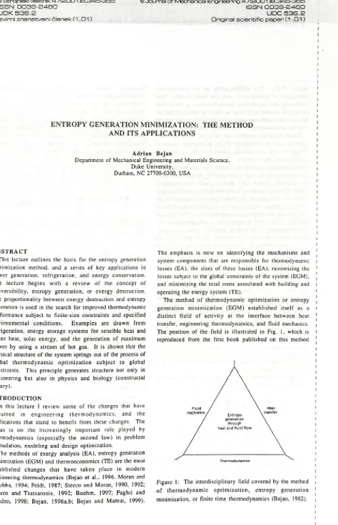
The method of thermodynamic optimization or entropy generation minimization (EGM) established itself as a distinct field of activity at the interface between heat transfer, engineering thermodynamics, and fluid mechanics. The position of the field is illustrated in Fig. I, which is reproduced from the first book published on this method
Figure l: The interdisciplinary field covered by the method o f therm odynam ic optim ization, entropy generation minimization, or finite time thermodynamics (Bejan, 1982).
i i i i I
i i
(Bejan, 1982). The method relies on the simultaneous application of principles o f heat and mass transfer, fluid mechanics, and engineering thermodynamics, in the pursuit of realistic models o f processes, devices, and installations. By realistic models we mean models that account for the inherent irreversibility of engineering systems.
Therm odynam ic optim ization may be used by itself (without cost m inim ization) in the preliminary stages of design, in order to identify trends and the existence of optim ization opportunities. The optim a and structural c h a ra c te ristic s id e n tifie d based on therm odynam ic optimization can be made more realistic through subsequent refin em en ts based on g lo b al co st m in im izatio n . Thermodynamic optimization may be used especially in areas where the total cost of the installation is dominated by the low temperatures, where the power requirement is substantial cost due to therm odynam ic irreversibility. The classical example o f this kind is cryogenics, or refrigeration at very and proportional to the entropy generated in the cold space. Many other applications are found in power generation and energy conservation, as shown by the examples collected in this paper.
T H E R M O D Y N A M IC S C O M B IN E D W IT H H E A T TRA N SFER AND FL U ID M E C H A N IC S
Here is why in thermodynamic optimization we must rely on heat tra n sfe r and flu id m e c h a n ic s, not ju st therm odynam ics. C onsider the most general system- environment configuration, namely a system that operates in the unsteady state. Its instantaneous inventories of mass, energy, and entropy are M, E, and S. The system experiences the net work transfer rate W , heat transfer rates
(Q o .Q ...Q n ) with n + 1 tem perature reservoirs (Tq, T | ... T n), and mass flow rates (m in, rhom) through any number of inlet and outlet ports. Noteworthy in this array of interactions is the heat transfer rate between the system and the environmental (atmospheric) temperature reservoir, Q 0 , on which we focus shortly.
The thermodynamics of the system consists of accounting for the first law and the second law [13],
dE dt
n
- w + X rhh - riih (1)
i= 0 in out
Š = ^gen
dS y
dt 2 - i t - x ms + ms £ 0. (2)
i = 0 1 in out
where h is shorthand for the sum o f specific enthalpy, kinetic energy, and potential energy of a particular stream at the boundary. In eq. (2) the total entropy generation rate Sgen is simply a definition (notation) for the entire quantity on the left-hand side of the inequality sign. We shall see that it is advantageous to decrease Sgen; this can be accomplished by
changing at least one o f the quantities (properties, interactions) specified along the system boundary.
We select the environmental heat transfer Q0 as the interaction that is allow ed to float as Sgen varies. Historically, this choice was inspired (and justified) by applications to pow er plants and refrigeration plants, because the rejection of heat to the atmosphere was of little consequence in the overall cost analysis of the design. Eliminating Q0 between eqs. ( 1 ) and (2) we obtain
i= l
W . - i ( E - T 0S) + X I ' - F
Q i +X m (h - T 0s ) ~ X ™ (h - T 0s) - T 0Sgcn (3)
in out
The. power output in the lim it o f reversible operation
Wrev= - A ( E - T°s) + X (
i- ^ Ì Q
ì+
i=l v i JX "> (h - T 0s) - X m ( h - T0S) <4>
in out
In engineering thermodynamics each of the terms on the right-hand side o f eq. (4) is recognized as an exergy of one type or another [2, 11-13], and the calculation of W rev is known as exergy analysis. Subtracting equation (3) from eq. (4) we arrive at the Gouy-Stodola theorem,
W rev - W = T 0Sgen (5)
In eq. (5) W rev is fixed because all the heat and mass flows (other than Qo ) are fixed.
Pure thermodynamics (e.g., exergy analysis) ends, and EGM begins with eq. (5). The lost power (W rev - w ) is always positive, regardless of whether the system is a power producer (e.g., pow er plant) or a power user (e.g., refrigeration plant). To minimize lost power when W rev is fixed is the same as maximizing power output in a power plant, and minimizing power input in a refrigeration plant. This operation is also equivalent to minimizing the total rate o f entropy generation. If W rev is not held fixed while the system design is being changed, then eq. (5) and the calculation of Sgen lose their usefulness.
The critically new aspect of the EGM method— the aspect that makes the use of therm odynam ics insufficient, and d istin g u ish e s EGM from exerg y a n a ly sis— is the
MKsfiFIRflülrS
minimization of the calculated entropy generation rate. To minimize the irreversibility o f a proposed design, the analyst m ust use the relatio n s betw een tem perature differences and heat transfer rates, and between pressure differences and mass flow rates. The analyst must express the thermodynamic nonideality of the design Sgen as a function of the physical characteristics o f the system, namely to finite dim ensions, shapes, m aterials, finite speeds, and finite-time intervals o f operation. For this the analyst must rely on heat transfer and fluid mechanics principles, in addition to thermodynamics. Only by varying one or more of the physical characteristics of the system, can the analyst bring the design closer to the operation characterized by minimum entropy generation subject to size and time constraints. We illustrate this technique by means of a few very basic models.
H IS T O R Y : LO W T E M P E R A T U R E R E F R IG E R A T IO N
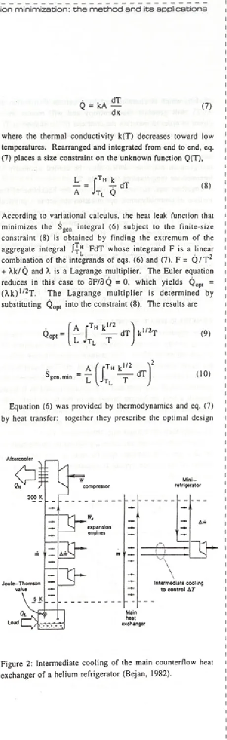
To a p p re c ia te the e n g in e e rin g o rig in s o f the thermodynamic optimization method (EGM), it is useful to recall that the field o f low temperature refrigeration was the first w here irre v e rs ib ility m inim ization becam e an established method of optimization and design. As a special application of eq. (5), it is easy to prove that the power required to keep a cold space cold is equal to the total rate of entropy generation times the ambient temperature, with the observation that the entropy generation rate includes the contribution made by the leakage of heat from Tq into the cold space (Bejan, 1982, 1988). The structure of a cryogenic system is in fact dominated by components that leak heat, e.g., mechanical supports, radiation shields, electric cables, and counterflow heat exchangers (Fig. 2). The minimization of entropy generation along a heat leak path consists of optim izing the path in harm ony with the rest of the refrigerator of liquifier.
Figure 3 shows a m echanical support of length L that connects the cold end o f the m achine (TL) to room temperature (TH). The rate o f entropy generation inside the support shown as a vertical column is
gen
- r
j TL H Q
dT (6)
where it is important to note that the heat leak Q is allowed to vary with the local tem perature T. The origin of the integrand in eq. (6) is the infinitesimal element (shaded in Figure 3). in which the rate of entropy generation is dSgen = Q / T + d Q /T - (Q + dQ )/(T + d T )= Q d T /T 2 . The local heat leak decrement dQ is removed by the rest of the installation, which is modeled as reversible. The heat leak is also related to the local temperature gradient and conduction cross-section A,
Q = (7)
where the thermal conductivity k(T) decreases toward low temperatures. Rearranged and integrated from end to end, eq. (7) places a size constraint on the unknown function Q(T),
_L A
f Tu k
4-
dTJt l Q (8)
According to variational calculus, the heat leak function that minimizes the Sgen integral (6) subject to the finite-size constraint (8) is obtained by finding the extremum of the aggregate integral JjJ* FdT whose integrand F is a linear combination of the integrands of eqs. (6) and (7), F = Q / T 2 + Xk/Q and X is a Lagrange multiplier. The Euler equation reduces in this case to 3F/3Q = 0, which yields Q op( = (X k )1/2T. The Lagrange m ultiplier is determined by substituting Q opt into the constraint (8). The results are
Equation (6) was provided by thermodynamics and eq. (7) by heat transfer: together they prescribe the optimal design
Figure 2: Intermediate cooling of the main counterflow heat exchanger of a helium refrigerator (Bejan, 1982).
I
! A. Bejsn: Entropy generation minimization: the method and its applications i
i
i i
(9, 10), which is characterized by a certain distribution of Q (T), will generate more entropy and will require more power in order to maintain the cold end of the support at TL. Quantitative and older examples are given in Bejan (1982, 1996a, 1997). An im portant exam ple is the main counterflow heat exchanger o f any low -tem perature refrigeration machine, which must be cooled optimally at intermediate temperatures (e.g., Fig. 2).
Together, eqs. (6) and (8) illustrate the backbone of the method of thermodynamic optimization subject to a physical constraint, as it was practiced in engineering before Bejan and Smith (1974) (this work was reviewed in the first book about the method: Bejan, 1982). In physics, the first application of the method is traced to Curzon and Ahlborn (1975), who rediscovered an optimization problem that had been solved 18 years earlier in engineering by Novikov (1957) and Chambadal (1957). Additional notes on the history of the method in both engineering and physics can be found in Bejan (1996c) and Bejan and Mamut (1999).
SENSIBLE H EAT STO R A G E
The opportunity for minimizing the destruction of exergy during energy storage becomes evident if we examine the system shown in Fig. 4. The storage system (the left side of the figure) contains a batch of liquid (m, c). The liquid is held in an insulated vessel. The hot-gas stream m enters the system through one port and is gradually cooled as it flows through a heat exchanger immersed in the liquid bath. The spent gas is discharged directly into the atmosphere. As time passes, the bath temperature T and the gas outlet temperature T0ut approach the hot-gas inlet temperature, T„,.
If we model the hot gas (steam, products of combustion) as an ideal gas with constant specific heat cp, the temperature history of the storage system is expressed in closed form by the equations
T 0„,(t) Tg
T . - T 0 = 1 - y exp ( - y0) (12)
where y and the dimensioniess time 6 are defined as
y = 1 - e x p ( - N,u ), N lu 0 = ™ L t (.3 )
mcp me
In these equations, Ab is the total heat-exchanger surface separating the stream from the liquid bath, and h b is the overall heat transfer coefficient based on Ab. Built into the model is the assumption that the liquid bath is well mixed, i.e., that the liquid temperature (T) is a function of the time (t) only. As expected, both T and Tout approach T „ asymptotically—the higher the N(U value, the faster.
Turning our attention to the irreversibility of the energy- storage process, Fig. 4 shows that the irreversibility is divided between two distinct parts of the apparatus. First, there is the finite-AT irreversibility associated with the heat transfer between the hot stream and the cold liquid bath. Second, the stream exhausted into the atmosphere is eventually cooled down to T0, again by heat transfer across a finite AT. Neglected in the present model is the irreversibility due to the pressure drop across the heat exchanger traveled by the stream m.
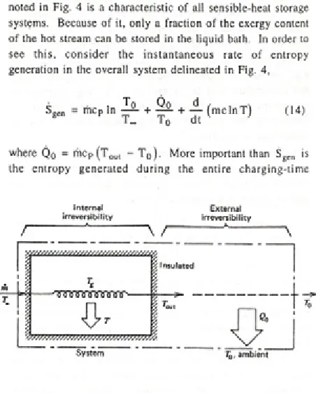
The combined effect of the competing irreversibilities noted in Fig. 4 is a characteristic of all sensible-heat storage systems. Because of it, only a fraction of the exergy content of the hot stream can be stored in the liquid bath. In order to see this, consider the instantaneous rate of entropy generation in the overall system delineated in Fig. 4,
Seen = rhcp In + — + JL (m cln T ) (14)
8 T „ T 0 dt v '
T (t) - T 0
T~ - T 0 = 1 - exp ( - y0)
where Q0 = rncP (T ou, - T 0 ). More important than Sge„ is the entropy generated during the entire charging-time
Internal External
irreversibility irreversibility
/
--- ---
\ /--- *--- \Figure 3: Mechanical support with variable heat leak and
intermediate cooling effect (Bejan and Smith, 1974). Figure 4: Two sources of irreversibility in the heating phase of a sensible-heat exergy-storage process (Bejan, 1982).
I I
____________LgftngitB^iRJiDžm 1 |^ggfiF!R3)C€i stran 3 4 8
interval 0 - t, which, using eqs. ( 11 )-( 14), can be put in dimensionless form as
—
f
Šge„dt = ej In +xi
+ ln (l + r n I )-T T || (15)me Jo V ‘ ~ )
where the first-law efficiency rjj is shorthand for the right side of eq. (11), and where x = (T „ - T 0 ) / T 0.
M ultiplied by T 0, the entropy-generation integral lo Šgcndt calculated above represents the bite taken by irreversibilities out o f the total exergy supply brought into the system by the hot stream:
Ex = tÉ x = tmcp In [t,*, - T 0 - T 0 In ( T „ / T 0 )] (16)
On this basis, we define the entropy-generation number Ns as the ratio of the lost exergy divided by the total exergy invested during the time interval 0 - t:
NS ( e ,x ,N tu) = J . f ' s gendt = b x Jo
. - - " ■ (; * " I ; 1 ( .7 , 6[x - In (l + x)j
This entropy-generation number takes values in the range 0 - 1, the Ns = 0 limit representing the elusive case of reversible operation. Note the relation N$ = 1 - fin. where T)jj is the second-law efficiency of the installation during the charging process.
Charts of the Ns(9, x, N,u) surface (Bejan, 1982) show that N s decreases steadily as the heat-exchanger size (N,u) increases. This effect is expected. Less expected is the fact that Ns goes through a minimum as the dimensionless time 9 increases. For example, the optimal time for minimum Ns can be calculated analytically in the limit x « I, where eq. (17) becomes
Ns = 1 - [l - exp ( - y6)]2 /9 (18)
The solution of the equation 3Ns/30 = 0 is
9opt = 1.256 [1 - exp (- Ntu)]-! (19)
In other words, for the common range of Ntu values (1-10), the optimal dimensionless charging time is consistently a number of order 1. This conclusion continues to hold as x takes values greater than 1.
Away from the optimal charging time (i.e., when 0 —> 0 or 0 oo), the entropy-generation number Ns approaches unity. In the short-time limit (0 « 9opi), the entire exergy content
of the hot stream is destroyed by heat transfer to the liquid bath, which was initially at atmospheric temperature T0. In the long-time limit (0 » 0 opt), the external irreversibility takes over. In this limit, the used stream exits the heat exchanger as hot as it enters (Tout = T ^) and its exergy content is destroyed entirely by the heat transfer (or mixing) with the T0 atmosphere. The traditional (first-law) rule of thumb of increasing the time of communication between heat source and storage material is counterproductive from the point of view of avoiding the destruction of exergy.
LATENT HEAT STORAGE
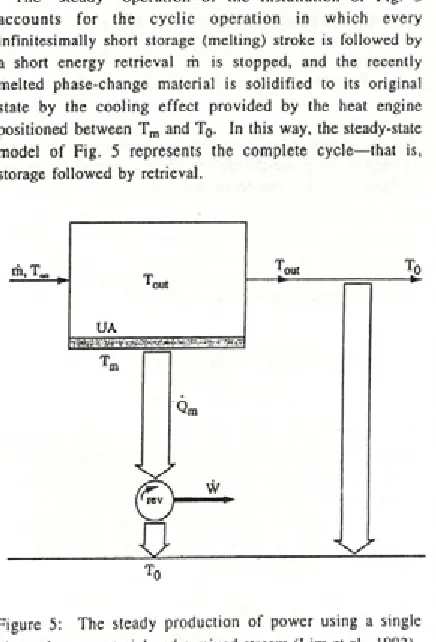
A simple way to perform the thermodynamic optimization of the latent heat storage process was proposed by Lim et al. (1992), Fig. 5. The hot stream of initial temperature TTC comes in contact with a single phase-change material through a finite thermal conductance UA, assumed known, where A is the heat transfer area between the melting malerial and the stream, and U is the overall heat transfer coefficient based on A. The phase-change material (solid or liquid) is at the melting point T m. The stream is well mixed at the temperature Tou,, which is also the temperature of the stream exhausted into the atmosphere (T0).
The "steady" operation of the installation of Fig. 5 accounts for the cyclic operation in which every infinitesimally short storage (melting) stroke is followed by a short energy retrieval m is stopped, and the recently melted phase-change material is solidified to its original state by the cooling effect provided by the heat engine positioned between Tm and T0. In this way, the steady-state model of Fig. 5 represents the complete cycle—that is, storage followed by retrieval.
Figure 5: The steady production of power using a single phase-change material and a mixed stream (Lim et al., 1992).
I g f in ^ O t - J lM lŽ llg D stran 3 4 9
The steady cooling effect o f the pow er plant can be expressed in two ways:
Qm ~ UA (Toui T m ) Q m — rhcp (T„, T oul) (20)
By eliminating Tout between these two equations we obtain
N„ Q m = mcp
1 + N ,
(T.
(21)in which NIU is the number of heat transfer units of the heat exchanger surface,
UA
N„ (22)
Of interest is the maximum rate o f exergy, or useful work ( W in Fig. 5) that can be extracted from the phase-change material. For this, we model as reversible the cycle executed by the working fluid between T m and T0
w = Q m 11 -‘ m y
and, after combining with eq. (21), we obtain
(23)
(24)
By maximizing W with respect to T m— that is, with respect to the type of phase-change material, we obtain the optimal melting and solidification temperature:
Tn.opt — (TooTq)1/2 (25)
The maximum power output that corresponds to this optimal choice of phase-change material is
(26)
Nm J H o
1/2'
1 + N,u \ T00 /
The same results, eqs. (25) and (26), could have been obtained by minimizing the total rate o f entropy generation, as in the preceding section. One way to improve the power output of the single-elem ent installation of Fig. 5 is by placing the exhaust in contact with one or more phase- change elements of lower tem peratures. This method is illustrated in Lim et al. (1992).
SO LA R C O L L E C T O R S
The optimization of solar energy conversion has been studied under the banners o f two fundamental problems. One
M l© inM lC €
| g r r igae)tJ^[iIsK3)| s tra n 3 5 0
is concerned with establishing the theoretical limits of converting thermal radiation into work, or calculating the exergy content of radiation. The other problem deals with the delivery o f maximum power from a solar collector of fixed size (Bejan et al., 1981). This problem has also been solved in many subsequent applications (Bejan 1996a, 1997a), which are united by an important design feature: the collector operating temperature can be optimized.
This optimization opportunity is illustrated in Fig. 6. A power plant is driven by a solar collector with convective heat leak to the ambient. The heat leak is assumed to be proportional to the collector-ambient temperature difference, Qo = (UA)C(TC - Tg). The internal heat exchanger between the collector and the hot end of the power cycle (the user) is modeled similarly, Q 0 = (UA)j(Tc - Tu). There is an optimal coupling between the collector and the power cycle such that the power output is maximum. This design is presented by the optimal collector temperature (Bejan, 1982)
1 c,opt ^max + j^£max
1 + R (27)
where R = (UA)c/(UA)j and 0max = Tc max/To is the maximum (stagnation) temperature of the collector. This optimum has its origin in the trade-off between the Carnot efficiency of the reversible part o f t h e power plant (1 - T0/T u) and the heat loss to the ambient, Q 0 . The power output is the product Q ( 1 — Tc/Tu). When T c < Tc opl the Carnot factor is too small. When Tc > Tcop, the heat input Q drawn from the collector is too small, because the heat loss to the ambient
Q0 is large.
Corresponding optimal couplings have been identified in solar-driven power plants of many power-cycle designs, extraterrestrial pow er plants, and refrigeration systems driven by solar power (Bejan 1996a, 1997a).
sun
collector
user
ambient
to reversible power plant
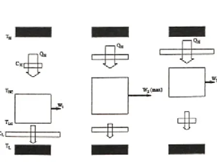
D ISTRIBU TIO N O F H EA T T R A N SFE R AREA Heat transfer principles combined with thermodynamics shed light on why energy systems are imperfect, and why they possess geom etric structure— why their hardware is arranged in certain amounts, and in certain ways in space. A power plant owes its irreversibility to many factors, one of which is the transfer o f heat across finite temperature differences. This effect has been isolated in Fig. 7. The power plant is the vertical segment marked between the high temperature T H and the ambient temperature TL. The heat input Qh (fixed) and the rejected heat QL must be driven by temperature differences: the temperature gaps T H - T HC and Tlc - Tl account for some of the space occupied by the power plant. Heat transfer surfaces reside in these spaces. The rest of the space is reserved for the rest of the power plant: for simplicity, this inner space is assumed to be irreversibility free,
C H + c l = c (31)
where C is fixed. This constraint is adequate when the overall heat transfer coefficients of the two surfaces are equal. More general constraints, valid for unequal heat transfer coefficients, can also be used.
The analytical model is completed by the first law, written for the power plant as a closed system operating in steady state or in an integral number of cycles, W = QH - QL. Combining this with the preceding relations, we obtain the power output as a function o f the conductance allocation fraction x = CH/C,
t l/t h
l -
°» fl
I Ì
t h c X I H
I X
(32)
Sge„ = ^ ^ = 0 (28)
1LC 1 HC
All the irreversibility o f this pow er plant model is concentrated in the two temperature gaps. The simplest heat transfer model for these is the proportionality between heat current and temperature difference,
Qh = Ch(Th- Thc) Ql = Cl(TUc- T l ) (2 9 ,3 0 )
Each thermal conductance (CH, CL) is proportional to its area for heat transfer. This is why the simplest way to account for the finiteness of the heat transfer surface available to the power plant is to recognize the constraint (Bejan, 1988)
Figure 7: Model of power plant with two heat transfer surfaces, and the maximization o f power output subject to Fixed heat input (QH) and fixed total heat transfer surface (C).
This expression can be maximized with respect to x, and the result is xop, = 1/2, or
Ch.oPi = Cl-opi (33)
In conclusion, there is an optimal way to allocate the constrained hardware (C) to the two ends of the power plant, that is, if the maximization of power output subject to fixed heat input (QH) and fixed size (C) is the purpose. Equation (33) also holds for refrigerating machines modeled in the same way.
The maximization of W is shown graphically in Fig. 7. Small conductances strangle the flow o f heat, and demand large temperature differences. The power output is large when the temperature difference across the reversible compartment is large. The first and third frames of Fig. 7 show that when the two conductances are highly dissim ilar in size, large temperature gaps are present, and the power output is small. The best irreversible perform ance is somewhere in the middle, where the conductances are comparable in size.
EXERGY EXTRACTIO N FR O M A STREAM OF HOT GAS
Thermodynamics alone provides an unambiguous answer to the question of the maximum power that is theoretically available from a stream solely in the presence of the atmospheric temperature reservoir (T0): that answer is the 'flow exergy' of the stream (Moran, 1989). It is helpful to review this result while looking at the upper part of Fig. 8 and assuming that the stream is single-phase, for example, an ideal gas. If the hot stream ( m , T H) makes contact with a reversible device while reaching thermal equilibrium with the ambient before it is discharged, and if the pressure drop along the stream is assumed negligible, the power output is
Wrev mCpT0 (34)
The actual power output will always be lower than W rev because of the irreversibility o f the heat transfer between the hot stream and the rest o f the power plant. A first step in the direction of accounting for the heat transfer irreversibility is the model of Fig. 8, where the heat transfer surface has the finite size A = pL, and p is the heat transfer area per unit of flow path length. The power producing compartment is a succession of many reversible com partm ents of the kind shown in the center o f the figure. The infinitesimal power output is
dW (35)
where the temperature is plotted on the vertical in Fig. 8, and dQH = rhCpdT. The heat transfer through the surface A is assumed proportional to the local temperature difference,
generation rate Sgen is the total amount associated with the larger system, and is due to two sources: the temperature difference T - Ts, and the finite temperature difference required by the external cooling rate Q c = m cp(T 0Ut - T0 ). These two contributions are represented by the two terms in the expression
CT h f i i i
rhCpdT +
( rr
me In 0 + ÒS.Ì
H Hl V. 1 1 1L n 111p T1 oul T 0 J
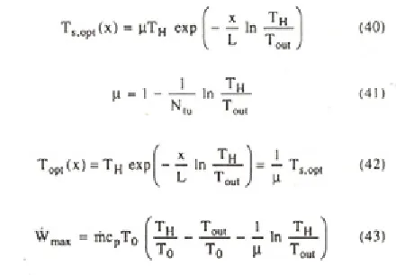
To maximize W is equivalent to minim izing Sgen, because W rev is fixed. The entropy generation rate (39) is subject to the size constraint (38). There are two degrees of freedom in the minim ization of Sgen: the shape of the surface tem perature function Ts(x), and the place of this function on the temperature scale (i.e., closer to T H or T0). The second degree o f freedom is alternately represented by the value of the exhaust temperature Toul. The optimization of the function T s(x) is accomplished based on variational calculus (Bejan and Errerà, 1998):
dQn = [T (x) - T s (x)]U pdx (36)
where U is the overall heat transfer coefficient, which is assumed constant. C om bining these equations and integrating from x = 0 to x = L (= A/p) we arrive at the total power output and the finite-area constraint:
^s,opt (*) ß T H exp - In —1
L T„
p = 1 --- L | n J Ü L
T opt(x ) = T H exp - - I n T H L T,out / - T
s.opt
^ max m C pT o Th _ T o u t L ]n Th
V T 0 T 0 p T ou,
(40)
(41)
(42)
(43)
An alternate route to calculating the power output W is to apply the Gouy-Stodola theorem (5) to the larger system (extended with dashed line) in Fig. 8. The reversible-limit power output W rev corresponds to the reversible cooling of the stream from T H all the way down to T0. The entropy
Figure 8: Power plant model with unmixed hot stream in contact with a nonisothermal heat transfer surface (Bejan and Errerà, 1998).
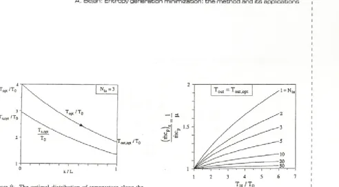
At any x, the temperature difference (T - T s) is proportional to the local absolute temperature. This optimal distribution of temperatures is illustrated in Fig. 9.
The second step o f the minimization of exergy destruction consists of maximizing numerically the expression (43) with respect to Tout. The result is the twice-maximized power output W max max reported in dimensionless form in Fig. 10,
^ mm — ^ max. max ( ( m C p T o ) (44)
It can be verified that this rate of exergy production approaches the reversible limit (34) as the surface size (N,u) increases.
The deduced proportionality between (T - Ts) and T (or Ts) means that this optimal configuration can be implemented in practice by using a single-phase stream (m cp ) in place of the Ts(x) surface: this stream runs in counterflow relative to
Figure 9: The optimal distribution o f temperature along the stream and the heat transfer surface of Figure 8 (Bejan and Errerà, 1998).
the hot stream m. The counterflow is characterized by a certain, optimal im balance (the ratio between the capacity flow rates o f the two stream s), which is the result of thermodynamic optimization, and is reported in Fig. 1 I.
Figure 10: The twice maximized power output corresponding to the model of Figure 8 (Bejan and Errerà, 1998).
t h/t0
Figure 11: The optimal imbalance of the counterflow heat exchanger used in conjunction with the model of Figure 8 (Bejan and Errerà, 1998).
G E O M E T R Y S P R IN G S O U T O F T H E R M O D YNAM IC O P T IM IZ A T IO N
In the preceding section, the maximization of exergy extraction (W j subject to fixed size (A) led to the physical structure of the flow system: the counterflow heat exchanger, and its optimal imbalance. The alternative is to minimize A subject to specified ( w ) , and in this case the optimal structure turns out to be the same. In all the examples reviewed in this paper, the physical result of global optimization of thermodynamic performance was structure. This structure-generating principle deserves to be pursued fu rth e r, in in c r e a s in g ly m o re com plex system configurations. The generation o f structure in engineering has been named constructal method.', the thought that the same principle accounts for the generation of shape and structure in natural flow systems is constructal theory (Bejan, 200 0) .
The principle o f organizing structure for the purpose of extracting and using maximum exergy from a hot stream is particularly relevant to the integrative conceptual design of energy flow systems for aircraft. The same principle applies to systems in which all the functions are driven by the exergy drawn from the limited fuel installed on board; ships, automobiles, military vehicles, environmental-control suits, portable power tools, etc. Additional support for this view is provided by the record on powered flight, engineered and natural. Figure 12 shows the cruising speeds of insects, birds and airplanes, next to the theoretical speed obtained by minimizing the power (exergy rate) destroyed during flight (Bejan, 2000).
Figure 12: Cruising speeds o f insects, birds and airplanes, and the theoretical speed for minimum rate of exergy destruction during flight (the solid line) (Bejan, 2000).
The performance record of the natural and engineered flow systems (e.g.,. Fig. 12) suggests that the constructai principle is important not only in engineering but also in physics and biology in general. In this theoretical framework the airplane emerges as a physical extension of man, in the same way that the body of the flying animal (e.g., bat, bird) developed its own well adapted extensions. All such extensions are evolutionary, discrete marks on a continuous time axis that points toward the better and the more complex. This theoretical line o f inquiry is explored in a new book (Bejan, 2000).
R EFE R E N C E S
Bejan, A., 1982, Entropy Generation through Heat and Fluid Flow, Wiley, New York.
Bejan, A., 1988, A dvanced Engineering Thermodynamics, Wiley, New York.
Bejan, A., 1996a, Entropy Generation Minimization, CRC Press, Boca Raton, FL.
Bejan, A., 1996b, Entropy generation minimization: the new thermodynamics of finite-size devices and finite-time processes, J. Appi. Phys., voi. 79, pp. 1191-1218. Bejan, A., 1996c, Notes on the history of the method of
en tro p y g e n e ra tio n m in im iz a tio n (f in ite tim e thermodynamics), J. Non-Equilib. Thermodyn., voi. 21, pp. 239-242.
Bejan, A., 1997a, Advanced Engineering Thermodynamics, second edition, Wiley, New York.
Bejan, A.. 2000, Shape and Structure, from Engineering to Nature. Cambridge University Press. Cambridge. UK. Bejan, A. and Errerà, M. R., 1998, Maximum power from a
hot stream, Int. J. Heat Mass Transfer, voi. 41, pp. 2025- 2Ö36.
Bejan, A. and Mamut, E., eds., 1999, T h e rm o d y n a m ic O ptim ization o f C omplex Energy Systems, Kluwer Academic Publishers, Dordrecht, The Netherlands. Bejan, A. and Smith, Jr., J. L., 1974, Thermodynamic
optim ization o f m echanical supports for cryogenic apparatus, Cryogenics, voi. 14, pp. 158-163.
Bejan, A. Kearney, D. W. and Kreith, F., 1981, Second law analysis and synthesis of solar collector systems, J. Solar Energy Eng., voi. 103, pp. 23-30.
Bejan, A., Tsatsaronis, G. and Moran, M., 1996, Therm al Design and Optimization, Wiley, New York.
Boehm, R. F., ed., 1997, Developments in the Design o f T herm al S y ste m s , C am bridge U niversity Press, Cambridge, UK.
Chambadal, P., 1957, Les Centrales Nucleaires, Armand Colin, Paris.
Curzon, F. L. and Ahlborn, B., 1975, Efficiency of a Carnot Engine at Maximum Power Output, Am. J. Phys., voi. 43, pp. 22-24.
Faghri, M. and Sunden, B., eds. 1998, M odeling o f Engineering Heat Transfer Phenomena, Computational Mechanics Publications, Southampton, UK.
Feidt, M., 1987, T h erm odynam ique et O ptim isation Energetique des Systémes et Procedés, Technique et Documentation, Lavoisier, Paris.
Lim, J. S., Bejan, A. and Kirn, J. H., 1992, Thermodynamic optimization of phase-change energy storage using two or more materials, J. Energy Resources Technology, voi.
114, pp. 84-90.
Moran, M. J., 1989, Availability Analysis: A Guide to
Efficient Energy Use, ASME Press, New York.
Moran, M. J. and Sciubba, E., 1994, Exergetic analysis: principles and practice, J. Eng. Gas Turbines Power, voi. 116, pp. 285-290.
Novikov, I. I., 1957, The efficiency o f atomic power stations, At. Energ., voi. 3, p. 409; English translation in 1958, J. Nuclear Energy lì, voi. 7, pp. 125-128.
Stecco, S. S. and Moran, M. J., eds., 1990, A Future fo r Energy, Pergamon, Oxford, UK.
Stecco, S. S. and Moran, M. J., eds., 1992, Energy fo r the Transition Age, Nova Science, New York.
Valero, A. and Tsatsaronis, G., eds., 1992, ECOS '92, Proc. Int. Symp. E fficiency, Costs, O ptim ization and Simulation o f Energy Systems, Zaragoza, Spain, ASME Press, New York.