Volume-4, Issue-4, August-2014,
ISSN No.: 2250-0758
International Journal of Engineering and Management Research
Available at:
www.ijemr.net
Page Number: 285-289
Modeling and Optimization of Crankshaft Design using ANSYS
Sri K. Prasad1, A.V.S.S.Somasundar2
1
Assistant Professor, Department of Mechanical Engineering, University College of Engineering (A), JNTU Kakinada, Andhra Pradesh, INDIA
2M.Tech (Machine Design) Student, Department of Mechanical Engineering, University College of Engineering (A), JNTU
Kakinada, Andhra Pradesh, INDIA
ABSTRATCT
In this study, a cast Iron crankshaft of a single cylinder 4 –stroke diesel engine was taken and a static analysis was conducted to get variation of stress magnitude at critical locations of the crankshaft. A model was created in CATIA of crank shaft and imported into ANSYS to carryout static analysis. Meshing of crankshaft was done; loads and boundary conditions were applied as per the mounting conditions of the crankshaft on Finite element model of crankshaft. Results obtained from the analysis were then used in optimization of the cast Iron crankshaft. Weight Optimization is achieved by varying the crankpin diameter. This requires the stress range in FE analysis not to exceed the magnitude of the stress range in the original crankshaft. The optimization process involves geometry changing without changing engine block.
Keywords– Diesel engine; finite element analysis; stress analysis; Crank shaft in Ansys; Optimization
__________________________________________________
I.
INTRODUCTION
Crank shaft is a large component in the I.C engine which converts the reciprocating motion of the piston to a rotary motion with a four bar link mechanism. Crank shaft is a large and very complex dynamic structure. Crankshaft consisting of shaft parts, two journal bearings and one crankpin bearing. The Shaft parts which revolve in the main bearings, the crank pins to which the big end of the connecting rod are connected, the crank arms or webs (also called cheeks) which connect the crank pins and shaft parts.
Crankshaft must be strong enough to take the downward force during power stroke without excessive bending. Hence the life and service are viewed from the strength perspective largely. The torsional vibration appears when a power impulse hits a crankpin toward the front of the engine and the power stroke ends. If not controlled, it can break the crankshaft.
The crankpin is like a built in beam with a distributed load along its length that varies with crank position. Each web
like a cantilever beam subjected to bending & twisting. Journals would be principally subjected to twisting.
C.M. Balamurugan et al [1] has studied the Computer aided Modeling and Optimization of crankshaft and compare the fatigue performance of two competing manufacturing technologies for automotive crankshafts, namely forged steel and ductile cast iron. The Three dimensional model of crankshaft were created by solid edge software and then imported to Ansys software. The optimization process included geometry changes compatible with the current engine, fillet rolling and results in increased fatigue strength and reduced cost of the crankshaft, without changing connecting rod and engine block.
Jian Meng et al. [2] analyzed crankshaft model and crank throw were created by Pro/ENGINEER software and then imported to ANSYS software. The crankshaft deformation was mainly bending deformation under the lower frequency. And the maximum deformation was located at the link between main bearing journal, crankpin and crank cheeks. Gu Yingkui et al. [3] researched a three-dimensional model of a diesel engine crankshaft was established by using PRO/E software. Using ANSYS analysis tool, it shows that the high stress region mainly concentrates in the knuckles of the crank arm & the main journal and the crank arm & connecting rod journal ,which is the area most easily broken.
Xiaorong Zhou et al. [4] described the stress concentration in static analysis of the crankshaft model. The stress concentration is mainly occurred in the fillet of spindle neck and the stress of the crank pin fillet is also relatively large. Based on the stress analysis, calculating the fatigue strength of the crankshaft will be able to achieve the design requirements
286 altered and stress analysis is carried out. The constituent
design that has less mass and optimum stresses is selected.
II.
MECHANICAL DESIGN
CALCULATIONS OF CRANKSHAFT
The specification of the diesel engine for this crankshaft is given in Table I
Table I Specifications of Kirloskar Engine
2.1 Design of crankshaft when the crank is at an angle of maximum thrust or maximum twisting Moment
Force on the Piston F p = Area of the bore x Max.Combustion pressure = π x D2
x P max /4 = 15.03KN
In order to find the thrust in the connecting rod (FQ), we should first find out the angle of inclination of the connecting rod with the line of stroke (i.e. angle Ø).
We know that Sin Ø = Sin θ/(L/R) = sin 35 0/4 which implies Ø = 8.24°
We know that thrust in the connecting rod FQ = FP/cos Ø From this we have, Thrust on the connecting rod FQ = 15.187 KN
Thrust on the crank shaft can be split into Tangential component and the radial component.
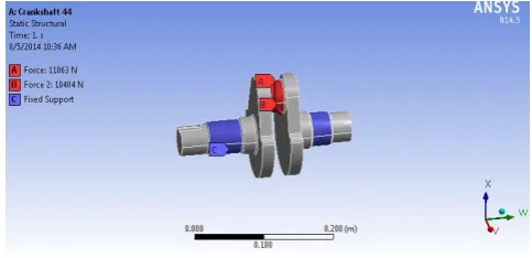
1) Tangential force on the crank shaft, FT = FQ sin (θ+ Ø) = 10.404 KN
2) Radial force on the crank shaft, FR = FQ cos (θ+ Ø) = 11.063 KN
Reactions at bearings (1 & 2) due to tangential force is given by,
HT1=HT2 = FT x b1/b = 5.202 KN (Since b 1=b2=b/2) Similarly, Reactions at bearings (1 & 2) due to radial
Force is given by, HR1 = HR2 = FR x b1/b = 5.5315 KN (Since b 1=b 2=b/2)
2.1.1 Design of crankpin
Let dc = Diameter of crankpin in mm.
We know that the bending moment at the centre of crank pin M = HR1 x b 2 = 5.5315 x 50 = 276.575 KN-mm Twisting moment on the crankpin, T = Ht1 × length of
stroke/2 = 286.11 KN-mm
From this we have the equivalent twisting moment Te = √M
2
+ T2 = 398 KN-mm
We know that equivalent twisting moment (Te)
T e = π x (dc)3 x τ/16
Shear stress value is limited to 35 N/mm2 , τ < 35N/mm2 So dc > 38.7mm (base design)
Modified design1 dc = 44mm Modified design2 dc = 41mm RESULT:
Design of crank pin against fatigue loading
According to distortion energy theory
The von Mises stress induced in the crank-pin is, Me = sqrt ((Kb.M)2+3/4(Kt.T)2) = 666.5 KN-mm
Here, Kb = combined shock and fatigue factor for bending (Take Kb=2)
Kt = combined shock and fatigue factor for torsion (Take K t =1.5)
Me = π dc3 σv/32
σv < 117 N/mm2
and also calculated shear stress of the shaft = 29.41N/mm2 RESULTS:
Length of the crankpin = 24 mm Diameter of the shaft = 41 mm
Web thickness (both left and right hand) = 18 mm Web width (both left and right hand) = 63 mm
III.
MODELING
Crankshaft model has been created in CATIA V5 software and exported as .igs file. This file is imported into ANSYS work bench to get the Crankshaft model.
IV.
LAODING AND BOUNDARY
CONDITIONS
Radial force is applied Tangential force is applied
Bearing supports are fully constrained. (Fixed supports)
Figure 1: Loading and boundary conditions
V. GEOMETRY OPTIMIZATION
In order to achieve the objectives various changes in the initial design of the crankshaft were done and they were analyzed among them two cases showed the most effective results.
Capacity 661.5 cc (cubic centimeters) Number of Cylinders 1
Bore x Stroke 87.5 x 110 mm Maximum power 6HP at 1500 rpm Compression Ratio 17.5:1
Figure 2: Modified design1 (crankpin dia 44mm)
Figure 3: Modified design2 (crankpin dia 41mm)
In modified design 1 Crankpin diameter is 44mm. Volume of the new design after modification is 7.7422e-4 m³ and the weight 6.0776 kg
In modified design 2 Crankpin diameter is 41mm.volume of the modified design 1 is 7.694e-4 m³ and the weight is 6.0398 kg
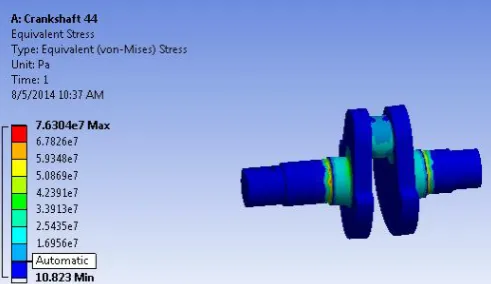
After designing the load and boundary conditions were assigned to the new model. After applying the loading and boundary conditions, equivalent (von-mises) stress, equivalent (von-mises) strain, shear stress and total deformation diagrams are obtained. After the analysis of von-mises stress, shear stress to be less than base design values and also to get weight reduction give the final optimized design
.
VI.
COMAPRISION OF RESULTS
After applying loading and boundary conditions results from ansys were obtained and compiled in table 1.
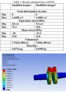
Table 1: Results obtained from ANSYS Modified design1 Modififed design2
Total deformation (in mm)
Min 0 0
Max 1.6458 e-5 1.6903 e-5 Equivalent stress(MPa) Min 10 e-6 7.8 e-6
Max 76.3 76.8
Shear stress(MPa)
Min -28 -33.3
Max 33.8 31.8
Volume(m3)
7.7422e-004 m³ 7.694e-004 m³ Mass(Kg)
6.0776 kg 6.0398 kg
Figure 4: Total Deformation of Modified Design 1
288
Figure 6: Equivalent Stress of Modified Design 1
Figure 7: Equivalent Stress of Modified Design 2
Figure 8: Shear Stress of Modified Design 1
Figure 9: Shear Stress of Modified Design 2
Figure 10: Equivalent Strain of Modified Design 1
Figure 11: Equivalent Strain of Modified Design 2
VII. CONCLUSION
Comparison of results
The results obtained are well in agreement with the similar available existing results. The model presented here, is well safe and under permissible limit of stresses.
Results show that Design2 is well within the safe limits
Results show that the weight of the crankshaft is also reduced by 38g. Thereby, reduces the inertia force. As the weight is reduced, frictional resistance also
reduced.
As the weight of the crankshaft is decreased this will decrease the cost of the crankshaft and increase the engine performance.
REFERENCES
[1] C.M Balamurugan, R. Krishnaraj, Dr.M.sakhivel, K.kanthavel, Deepan Marudachalam M.G, R.Palani, “Computer Aided modelling and optimization of Crankshaft”, International Journal of scientific and Engineering Research, Vol-2, issue-8, ISSN: 2229-5518, August-2011. [
[2] Jian Meng., Yongqi Liu., Ruixiang Liu., 2011, “Finite Element Analysis of 4-Cylinder Diesel Crankshaft,” I.J. Image, Graphics and Signal Processing, 5, 22-29
[3] Gu Yingkui, Zhou Zhibo.,2011,“Strength Analysis of Diesel Engine Crankshaft Based on PRO/E and ANSYS,” Third International Conference on Measuring Technology and Mechatronics Automation
[4] Xiaorong Zhou., Ganwei Cai., Zhuan Zhang. Zhongqing Cheng., 2009, “Analysis on Dynamic Characteristics of Internal Combustion Engine Crankshaft System,” International Conference on Measuring Technology and Mechatronics Automation.
[5] Rincle Garg, Sunil Baghla, “Finite element analysis and optimization of crankshaft”, International Journal of Engineering and Management Reaserch, vol-2, Issue-6, ISSN: 2250-0758, Pages: 26-31, December 2012.
[6] R.J Deshbhratar, Y.R Suple, “Analysis and optimization of Crankshaft using FEM”, International Journal of Modern Engineering Research, vol-2, issue-5, ISSN: 2249-6645, pages: 3086-3088, Sept-Oct 2012.
[7] A. Solanki, K. Tamboli, M. J. Zinjuwadia, (2011), “Crankshaft Design and Optimization- A Review” National Conference on Recent Trends in Engineering & Technology [8] Farzin H. Montazersadgh and Ali Fatemi., 2007,“Dynamic Load and Stress Analysis of a Crankshaft,” SAE Technical Paper No. 010258, Society of Automotive Engineers
[9] JonathanWilliams, FarzinMontazersadgh, andAlifatemi. 200 7,“FatiguePerformance Comparison And Life Prediction Of Forged Steel And Ductile Cast Iron Crankshafts,” Published in Proceeding of the 27th Forging Industry Technical Conference in Ft.Worth,Texas
[10] Shenoy, P. S. and Fatemi, A., 2006, “Dynamic analysis of loads and stresses in connecting rods,”IMechE, Journal of Mechanical Engineering Science, Vol. 220, No. 5, pp. 615- 624.
[11] S. Ai-ling, Y. Wen-hua, D. Zhou, L. Yu-mei, (2010), “Assessment of Residue Fatigue Life of Crankshaft Based on Theory of Fatigue Damage” International Conference on Optoelectronics and Image Processing
[12] X. Zhou, G. Cai, Z. Zhang, Z. Cheng, (2010), “The Whole Crankshaft Model for Dynamic Simulation Analysis of the Diesel Engine” Institute of Electrical and Electronic Engineers.
[13] C. Xiaoping, Y. Xiaoli, J. Binwei, (2010), “Study of crankshaft Strength based on iSIGHT Platform and DOE Methods” International Conference on Measuring Technology and Mechatronics Automation, pp 548-551
[14] Z. Guangming, J. Zhengfeng, (2009), “Study on Torsional Stiffness of Engine Crankshaft” International Forum on Computer Science Technology and Applications, pp 431-435
[15] Prakash, V., Aprameyan, K., and Shrinivasa, U., 1998, “An FEM Based Approach to Crankshaft Dynamics and Life Estimation,” SAE Technical Paper No. 980565, Society of Automotive Engineers
[16] Payar, E., Kainz, A., and Fiedler, G. A., 1995, “Fatigue Analysis of Crankshafts Using Nonlinear Transient Simulation Techniques,” SAE Technical Paper No. 950709, Society of Automotive Engineers
[17] Guagliano, M., Terranova, A., and Vergani, L., 1993, “Theoretical and Experimental Study of the Stress Concentration Factor in Diesel Engine Crankshafts, “Journal of Mechanical Design, Vol. 115, pp. 47-52
[18] Henry, J., Topolsky, J., and Abramczuk, M., 1992,“Crankshaft Durability Prediction – A New 3-D Approach,” SAE Technical Paper No. 920087, Society of Automotive Engineers
[19] Stephens, R. I., Fatemi, A., Stephens, R. R., and Fuchs, H. O., 2001, “Metal Fatigue in Engineering,”2nd edition, John Wiley and Sons, New York, NY,USA co.