Enhancement of Cooling in Central Processing
CPU by using Jet Impingement with and without
Nano Fluid
Sumeet Singh Rahul Singh
Student Student
Department of Mechanical Engineering Department of Thermal Engineering Gautam Buddha University Greater Noida, India Gautam Buddha University Greater Noida, India
Harishchandra Thakur
Assistant Professor
Department of Thermal Engineering Gautam Buddha University Greater Noida, India
Abstract
The heat released from the flat surface is cooled by the use of jet impingement technique. The heat flux from the isothermally heated flat surface due to two-dimensional turbulent twin oblique confined slot-jet impingement is studied numerically using the ANSYS FLUENT software. Initially the flow and thermal fields for a normal confined slot-jet impingement are investigated using the RNG k-ε model and the SST k- ω model. The local Nusselt number distribution predicted by the SST k-ω model agrees notably better with the existing experimental data. Subsequently, the SST k-ω is employed to study the twin oblique impinging jet heat transfer problem. The study is conducted by varying the jet exit Reynold number, the jet to jet separation distance, jet -exit to target plate distance and the inclination angle of the jet to the impingement. Results indicate that impingement angle is reduced from 90o, the peak Nusselt number at the impingement surface is gradually reduced and its location slightly shifts away from the axis with slight decrease of the average Nusselt number for any combination of Re, L, H. The average Nusselt number is a direct function of the Reynold number and the impingement angle and is inverse function of the jet to target plate separation distance.
Keywords: J/d ratio, Nusselt number, friction factor, LMTD, pumping power, jet impingement, Reynold number, axisymmetric
_______________________________________________________________________________________________________
I.
I
NTRODUCTIONIn today’s modern world, there are many products available for consumers to be used in all ranges, from food to clothing, electrical appliances to transportation. But little do we know, lots of these products such as electronic devices e.g. laptops , computers and game consoles , heat exchangers e.g. refrigerator heater and air conditioner and transportation vehicles need to have a liquid coolant to prevent the overheating or to improve the rate of heat transfer[1]. However, the liquid coolant or heat transfer fluids that we have today such as water, engine oil etc. generally have poor thermal properties. For more than 100 years, many scientist and engineers have made great efforts to improve the poor thermal conductivities of these traditional heat transfer fluids as shown in Fig 1. .
An innovative way of improving the thermal conductivities of the heat transfer fluids is to suspend solid particles in the fluids. In order to achieve Nano fluids have been used. Nano fluids are nanometer – sized particles less than 100 nm dispersed in a base fluids such a water, ethylene glycol etc. Addition of high thermal conductivities of such mixtures thus enhancing their overall energy transport capability.
Nano fluids are next generation heat transfer fluid and they offer exciting possibilities due to their enhanced heat transfer performance compared to ordinary fluids. Some of the advantages of these Nano fluids are
1) Better stabilities and heat transfer ability compared to those fluids containing micro and mili-sized particles.
2) Higher thermal conductive capability than the base fluids themselves because of large surface size for heat transfer due to smaller size of the particles.
An effective method of enhancing localized heat transfer is achieved by impinging jets on the heated surfaces. Impinging jets are widely used in industrial areas for thermal drying of continuous sheets like paper, textiles, glass, lumber, films, cooling of turbine blades, annealing of metal sheets, tempering of glass, de- icing of aircraft wings, cooling of electronic equipment.
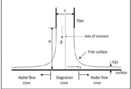
Jet impingements can be used for laminar to highly turbulent flow depending on the application. [2] The impinging jet flow has a simple geometry but the resulting flow physics is complex in nature. Al Aqal categorized this complex flow field of single impingement jet into three regions which are as follows.
1) The zone directly beneath the nozzle.
2) Stagnation zone characterized by pressure gradient. 3) Wall jet zone that is free of pressure gradients.
There have been a number of researches which have been conducted over the years on the heat transfer due to single jet impinging on the flat surfaces, both in experimental and numerical field. But this area of research still draws attention to researchers because of the complex fluid dynamics and many engineering application of this topic. Polat et al reviewed the numerical study of impinging jet flow and heat transfer earlier than 1989.
Single, normally impinging, jets are efficient for localized heat transfer from the impingement location on a surface. For distributed cooling or heating of an extended surface multiple impinging jets can be used. But the flow physics for multiple jet impingements become very complicated in nature because the spent fluid flow from the upstream moves along the surface as wall jet and then interacts with downstream impinging jet flow. It degrades the heat transfer efficiency of the downstream jet.
Fig. 1: Axisymmetric Jet impingement
The jet impingement technique has been widely applied to engineering problems that require high heat and mass transfer efficiency for cooling, heating etc. There are wide areas where the heat dissipation of high power electronic chips, glass processing, steel sheet cooling etc. Various industries have already started using this technique to cool the heat dissipating elements for protecting the components which can be affected by the heat. In recent years the computation power of the computers and other electronic components have increased exponentially. Therefore there is dire need of this technique in electronic cooling.
Fig. 2: Axisymmetric Jet impingement in two dimensional view
needed for cooling of fuel cell stacks and concentrated solar cells, which is one of the newest form of solar energy technology. This can be achieved by the use of jet impingement technique.
II.
L
ITERATURE REVIEWAl Aqal categorized this complex flow field of single impingement jet into three categories (i) the zone directly beneath the nozzle, (ii) stagnation zone characterized by pressure gradient, and (iii) wall jet zone that is free of pressure gradients.
Polat et al published a comprehensive review on the numerical study of impinging jet flow and heat transfer earlier than 1989. The recent published studies on the jet impingement cooling, these works relates to jets, above which it acts like an assembly of single jets.
Recent researches trends of computational impinging jet heat transfer has been compiled by Dewan et al. Contemporary studies on the topic involves impingement jet in cross flow , multiple jet impingement , jet impingement on the moving plate, oblique impingement, pulsed jet, swirling jet impingement.
Go conducted experimental investigation of multiple jet impingement and showed stagnation point Nusselt number.
Experimental investigation of Saad et al. for multiple impinging jets with exhaust ports alternatively located on the confining wall shows that there is a critical value for spacing between the multiple jets, above which it acts like an assembly of single jets Numerical investigation was done by Mushatet to study the heat transfer and fluid flow of multiple impinging jets , impinging perpendicular to the backward facing step cross flow. Their research showed that the heat transfer is enhanced significantly by using multiple impinging jets. Heat transfer was highest near the region of the facing step and the rate of heat transfer can be increased by increasing the jet sizes.
Multiple jet impingement experimental studies have been conducted for fluid injecting from a row of five round jets on to a rotating circular concave passage of semi –circular cross section. Local Nusselt number measurements at concave surfaces shows a high Nusselt number at concave surface shows a high Nusselt number region developing around each impingement point, along with secondary peaks for Nusselt number at the half –way between impingement points.
Abdel-Fattah conducted numerical and experimental investigation of normal and oblique twin turbulent round jet impingement. It is revealed from the investigation that the primary stagnation point shifts away in the radial main flow direction with jet inclination. As the nozzle- to-nozzle center spacing increases, the shift becomes stronger.
III.
M
OTIVATIONALThe heat flux from the electronic component is more than 150 W/ m2 .Therefore the processing power of the computer and other smart electronic devices is increasing at an exponential rate [2]. Therefore these heat guzzling machines need to be cooled at a rate which will not be able to penetrate the soft and heat prone components.
This is focused on impingement cooling. Impingement cooling has the advantage of a thin boundary layer due to the stagnation point flow when the jet core impacts the target surface. Additionally, mixing of the cool supply air and the hotter, spent air is reduced due to the separation of these two fluids by an impingement nozzle plate. Unfortunately, when large arrays of impingement jets are implemented inside a gas turbine blade, cross flow effects from spent jet air reduce the cooling effectiveness of downstream jets. The jet is bent, the strength of the jet is reduced, and the spent air engages in additional mixing prior to impacting the surface to be cooled. The earliest techniques utilized arrays of thermocouples to study the spatially dependent heat transfer coefficients on an impingement target surface [1, 2].
Due to the free shear layer, a recirculation is induced in the surrounding fluid. After impacting the target surface, the impingement jet fluid then travels to an exit. Depending on the application, the fluid can exit in all directions or just one specific direction. As was just mentioned, impingement jets can be used to heat or cool the target surface. Due to the exclusive use of impingement jets for cooling applications in gas turbine blades, the present work focuses primarily on the use of impingement jets for cooling applications. Additionally, impingement jets can be multiphase, however, due to the use of only air in gas turbine blade cooling, only single phase impingement jet heat transfer is studied in the present work.
IV.
O
VERVIEW OF IMPINGEMENTImpingement jets can be used as a heat transfer enhancement technique to either heat or cool the target surface. A schematic of a sectional view of a single impingement jet is presented in Figure, Figure 1.1 illustrates several key features of impingement jet flow and impingement jet nozzles. Impingement jets are typically either slot jets or cylindrical jets, which in the sectional view presented in Figure 1.1 appear the same. Cylindrical impingement jet nozzles are typically mandated in gas turbine blade applications due to structural and manufacturing requirements of the gas turbine blade. The present work focuses exclusively on cylindrical impingement jet nozzles. Fluid in a higher pressure reservoir, typically referred to as the pressure chamber, is accelerated through the impingement nozzle, and then impacts the target surface at a high velocity. A free shear layer exists between the high velocity fluids, known as the jet core. Due the sharp drop in convective heat transfer as the boundary layer thickens as the fluid travels away from the jet core, multiple impingement jets are typically needed in order to heat or cool a large surface area. In Figure 1.2, the exhaust fluid is given the opportunity to exit in two directions. The total mass flow rate through the cross section increases as the exhaust fluid travels towards the exits because the exhausted fluid (cross flow) times be described as the interaction between two neighboring jets. As can be seen in Figure 1.1, the high velocity fluid turns after impacting the target surface and becomes a ``wall jet'' parallel to the target surface. With two nearby jets, the resulting two ``wall jets'', which are parallel to the target surface, interact with each other, and cause a second stagnation region. In this second stagnation region, the boundary layer thickens, and the heat transfer coefficient is reduced.as it can be seen from Fig 3. The purpose of the present study is to better characterize the effects of the cross flow and jet to jet interactions on jet performance in impingement jet arrays. Although the application of impingement cooling to gas turbine blades is of primary interest, the geometry studied was much simpler than typically found in a gas turbine blade. The impingement jet nozzles were arranged in a rectangular patter. The target surface was flat. The impingement jet nozzle plate was primarily rectangular in cross section. In an application found in an actual turbine blade, curved nozzle plates and target surfaces would be required, and unequal placement of impingement jet nozzles may be necessary due to the cooling needs of the turbine blade. In addition, no rotational affects were studied, which would be present in an actual, rotating turbine blade [3].
V.
C
OMPUTATIONAL FLUID DYNAMICS(
CFD)
Computational fluid dynamics, usually abbreviated as CFD, is a branch of fluid mechanics that uses numerical methods and algorithms to solve and analyze problems that involve fluid flows. Computers are used to perform the calculations required to simulate the interaction of liquids and gases with surfaces defined by boundary conditions. With high-speed supercomputers, better solutions can be achieved. Ongoing research yields software that improves the accuracy and speed of complex simulation scenarios such as transonic or turbulent flows.
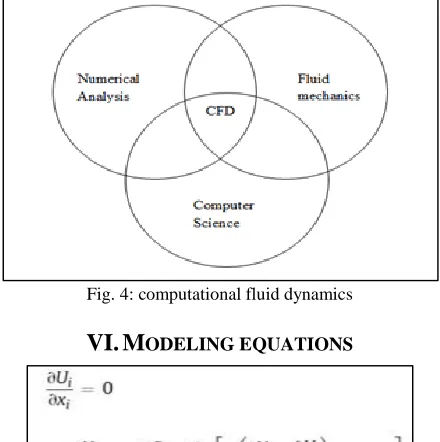
Computational fluid dynamics basically combination of numerical analysis, fluid mechanics and computer science. Numerical analysis the heart of computational fluid dynamics. Computer science plays in essential roil for calculation help of computers. Fluid mechanics use for flow visualization and other vary important conclusions.
Fig. 4: computational fluid dynamics
where P, T, Ui are the mean pressure, temperature and velocity components respectively Tʹ and ui ʹare the fluctuating temperature and velocity components respectively xi is the coordinate direction µ, ρ and Pr are the fluid density, dynamic viscosity and Prandtl number respectively.
The Reynold average mass momentum and energy conservation for the steady incompressible flow are given as follows. In these formulae viscous dissipation is neglected.
VII.
B
OUNDARY CONDITIONSThe bottom impingement surface is isothermal wall at a constant temperature
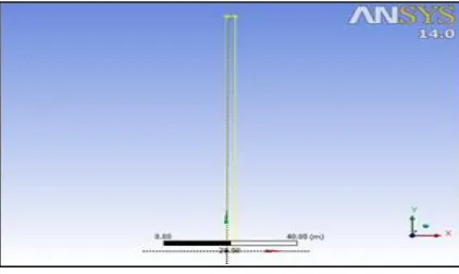
Fig. 5: Design modelling in ANSYS
VIII.
S
KETCHINGThe sketching is made on the x – y axis and there is no z dimension in the problem as we have taken 2d geometry. A rectangle is made with dimensions 100 m as heat flux on the x axis which is length of rectangle. The breadth of the rectangle is given as 2.6 m which is as per our problem statement [6. There is a slight change of angle of impingement of our jet impinging onto the surface of the heat flux element. For including and analyzing the effect of angle on the surface of the jet inlet is changed slightly according to impinging angles which are φ = 45, 48, 60, 75. [7]
Fig. 6: Shown on design modeler with dimensions
IX.
S
OLUTION INITIALIZATION The compute from tab is kept at inlet and initialize button is pressed.X.
R
UN CALCULATIONThe number of iteration is kept at 400
XI.
R
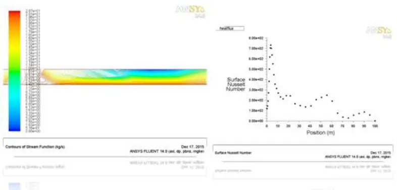
ESULTS AND DISCUSSION
Fig. 7: At Reynold Number 23000 angle of impingement 75
Fig. 8: At Reynold Number 23000 angle of impingement 75
Fig. 10: At Reynold number 50000 angle of impingement = 75
Fig. 11: At Reynold number 50000 angle of impingement = 90
Fig. 12: At Reynold number 23000 jet impingement angle 90
XII.
C
ONCLUSIONFrom the investigation the following conclusion has been made:
The heat transfer coefficient h, increases as Nusselt number increases. But up to certain limit i.e. between ranges of 23000 to 50000.
The best optimum value of his 3 as at this neither there will be greater geometry adjustments or the
We require to make Nusselt number in coordination to Reynold number as this increases heat transfer coefficient. .
As the jet impingement angle increases from 30 to 75 we observe that the Nusselt number remains constant at 831 which lies in turbulent region
A
CKNOWLEDGMENTWe would like to be thankful to the Gautam Buddha University, Greater Noida. At the same time we could not forget the direct or indirect support of faculty and friends to make this paper successful.
R
EFERENCES[1] DM Kercher and W. Tabakoff. Heat transfer by a square array of round air jets impinging perpendicular to a flat surface including the effect of spent air. J. Eng. Power, 92(1):73--82,1970.
[2] LW Florschuetz, DE Metzger, DI Takeuchi, and RA Berry. Multiple jet impingement heat transfer characteristic: Experimental investigation of in-line and staggered arrays with crossflow.1980.
[3] O.M. Al-Aqal, Heat Transfer Distributions on the Walls of a Narrow Channel with Jet Impingement and Cross Flow. Doctoral dissertation, University of Pittsburgh, 2003
[4] S. Polat, B. Huang, A.S. Mujumdar, W.J.M. Douglas, Numerical flow and heat transfer under impinging jets: a review, Ann. Rev. Heat Transfer 2 (2) (1989) 157e197.
[5] G. Morris, S. Garimella, R. Amano, Prediction of jet impingement heat transfer using a hybrid wall treatment with different turbulent Prandtl number functions, J. Heat Transfer 118 (1996) 562e569.
[6] G. Morris, S. Garimella, J. Fitzgerald, Flow-field prediction in submerged and confined jet impingement using the Reynolds stress model, J. Electron. Packag. 121 (1999) 255.
[7] T. Cziesla, G. Biswas, H. Chattopadhyay, N. Mitra, Large-eddy simulation of flow and heat transfer in an impinging slot jet, Int. J. Heat Fluid Flow 22 (2001) 500e508.
[8] K.S. Choo, Y.J. Youn, S.J. Kim, D.H. Lee, Heat transfer characteristics of a micro scale impinging slot jet, Int. J. Heat Mass Transfer 52 (2009) 3169– 3175.
[9] M.K. Isman, E. Pulat, A.B. Etemoglu, M. Can, Numerical investigation of turbulent impinging jet cooling of a constant heat flux surface, Numer. Heat Transfer, Part A 53 (2008) 1109–1132.
[10] H. Thomann, Effect of stream wise wall curvature on heat transfer in a turbulent boundary layer, Journal of Fluid Mechanics 33 (1968) 283-292. [11] P.D. McCormack, H. Welker, M. Keeleher, Taylor-Gortler vortices and their effect on heat transfer, ASME J. of Heat Transfer 92 (1970) 101-112. [12] P. Hrycak, S. Jachna, D.T. Lee A study of characteristics of developing, incompressible, axisymmetric jets .Lett. Heat Mass Transfer, 1 (1974), pp. 63–71 [13] [R. Gardon, J. Cobonpue Heat transfer between a flat plate and jets of air impinging on it .Int. Heat Transfer Conf., Pt. 2 (1961), pp. 454–460.