Supporting Virtualisation Management
through anObject Mapping Declarative Language Framework
Glyn David HughesA thesis submitted in partial fulfilment of the requirements of Liverpool John Moores University
for the degree of Master of Philosophy
Abstract
Due to the inevitably vast scale of virtualised cloud computing systems, management of the numerous physical and virtual components that make up their underlying infrastructure may become unwieldy. Many software packages that have historically been installed on desktops / workstations for years are slowly but surely being ported to cloud computing. The virtualisation management problems that are apparent today are only set to worsen as cloud computing systems become ever more pervasive.
Backing cloud computing systems are equally elaborate database systems, many platforms of which have made extensive use of distributed computing and virtualisation for years. The more recent emergence of virtualised big data systems with similarly vast scale problems has escalated the urgent requirement for creative management of the numerous physical and virtual components.
The thesis will initially synopsise previous investigatory research concerning these emerging problems and studies the current disposition of virtualisation management including the associated concepts, strategies and technologies. The thesis then continues, to describe the structure and operation of an object mapping declarative language to support the management of these numerous physical and virtual components. The ultimate aim is to develop a Virtualisation Management System (VMS), a software framework that is fully extensible in nature and which combines the rich capability of an imperative assembly with the concise simplicity of a declarative language.
It is through this declarative language that human interaction and decision making may be richly yet concisely specified before being converted through object mapping to the comparable imperative assembly for execution. It is also through parsing this declarative language that autonomic algorithms may be able to integrate with and operate the VMS through a suitably defined plug-in based mechanism.
The thesis will ultimately demonstrate via scenarios both basic and complex that the VMS is able to specify, observe, regulate and adapt its virtualisation management domain to the changing disposition of the numerous physical and virtual components that constitute cloud computing and big data systems.
Acknowledgments
Directors of Study :Dr. Dhiya Al-Jumeily - Liverpool John Moores University Dr. Abir Hussain - Liverpool John Moores University
Table of Contents
Abstract ii
Acknowledgments iii
Table of Contents iv
Table of Figures viii
Glossary of Terms ix
List of Publications xi
Chapter One ~ Introduction 1
1.1. Overview 1
1.2. Motivation 1
1.3. Research & Development Question 2
1.4. Aims & Objectives 2
1.5. Contributions to Knowledge 2
1.6. Research & Development Activity 3
1.6.1. Ethical Considerations 4
1.7. Thesis Structure 5
Chapter Two ~ Cloud Computing 7
2.1. Overview 7
2.2. Principle Architecture & Underlying Technology 8
2.3. Service Models 9
2.3.1. SaaS (Software as a Service) 9
2.3.2. PaaS (Platform as a Service) 9
2.3.3. IaaS (Infrastructure as a Service) 10
2.4. Cloud Computing’s Positioning 10
2.5. Relationship with Virtualisation 10
2.5.1. The Management Problem 11
2.6. Summary 11
Chapter Three ~ Big Data 12
3.1. Overview 12 3.2. Technology Stack 13 3.2.1. OLTP 13 3.2.2. ETL 14 3.2.3. OLAP 14 3.2.4. Data Analytics 15
3.2.6. Bespoke Big Data Applications 15
3.3. Relationship with Virtualisation 16
3.3.1. The Management Problem 16
3.4. Summary 17
Chapter Four ~ Virtualisation 18
4.1. Overview 18
4.2. Types of Hypervisors 18
4.3. History of Hypervisors 19
4.4. Hypervisor Technology 19
4.4.1. Type-One (Native Hypervisors) 20
4.4.2. Type-Two (Hosted Hypervisors) 20
4.5. Operation of Hypervisors (Hyper-V Case Study) 21
4.5.1. Partitions 22
4.5.2. VSP (Virtualization Service Providers) & VSC (Virtualization Service Clients) 23
4.5.3. VMBus 23
4.5.4. Virtual Machine Management Service 23
4.5.5. Virtual Machine Worker Process 23
4.6. Management of Hypervisors (Hyper-V Case Study) 23
4.7. Summary 25
Chapter Five ~ Programming Paradigms 26
5.1. Overview 26
5.2. Programming Language Design 26
5.2.1. Expressivity 26
5.2.2. Abstraction 26
5.2.3. Inheritance & Polymorphism 27
5.2.4. Portability 27
5.2.5. Exception Handling 27
5.3. The Imperative Language 28
5.4. The Declarative Language 28
5.4.1. Object Mapping 29
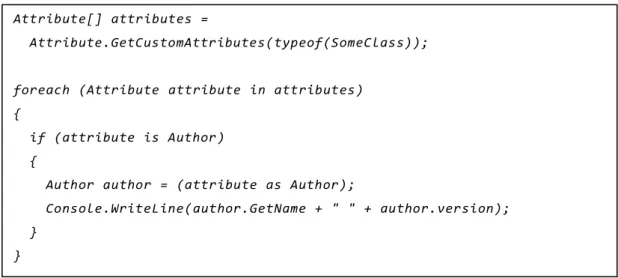
5.4.2. Attribute Oriented Programming 31
5.5. The Multi-Paradigm Language 33
5.6. Summary 34
Chapter Six ~ Framework Requirements 35
6.1. Overview 35
6.3. Human Interaction & Automatic / Autonomic Support 36
6.4. Summary 37
Chapter Seven ~ Framework Design 38
7.1. Overview 38
7.2. Physical Architecture 38
7.3. Software Components 39
7.4. Object Model 41
7.5. Operating Principle 42
7.5.1. Scheduling with System Agent 45
7.6. Object Mapping Declarative Language 45
7.6.1. Key / Value vs Property 49
7.6.2. Pre-Set Defaults 49
7.7. Summary 51
Chapter Eight ~ Verification & Validation 52
8.1. Overview 52
8.2. Types of Scenario 52
8.3. Scenario One (Problem & Solution) 52
8.4. Scenario Two (Problem & Solution) 56
8.5. Hypervisor Interaction 61
8.5.1. Default System Image Repository 62
8.5.2. Package Deployment 62
8.6. Human Interaction 62
8.6.1. Management DashBoard 64
8.6.2. Supporting the DashBoard 65
8.7. Immediate Limitations 66
8.8. Automatic / Autonomic Support 67
8.9. Summary 68
Chapter Nine ~ Conclusions & Future Work 69
9.1. Overview 69
9.2. Aims & Objectives Accomplished 69
9.3. Contributions to Knowledge 70
9.4. Research & Development Constraints 71
9.4.1. Access only to Local Servers 71
9.4.2. Long Term Data Storage / Archiving 71
9.4.3. Exception Handling 71
9.5.1. Autonomic Capability 72
9.5.2. Interoperability 72
9.5.3. Visualisation 72
9.6. Concluding Remarks 73
Table of Figures
Figure 1.1 - Research & Development Map 4
Figure 2.1 - Cloud Computing Principle Architecture 8
Figure 3.1 - Big Data Technology Stack 13
Figure 4.1 - Hypervisor Technology 20
Figure 4.2 - Hyper-V Technology Stack 22
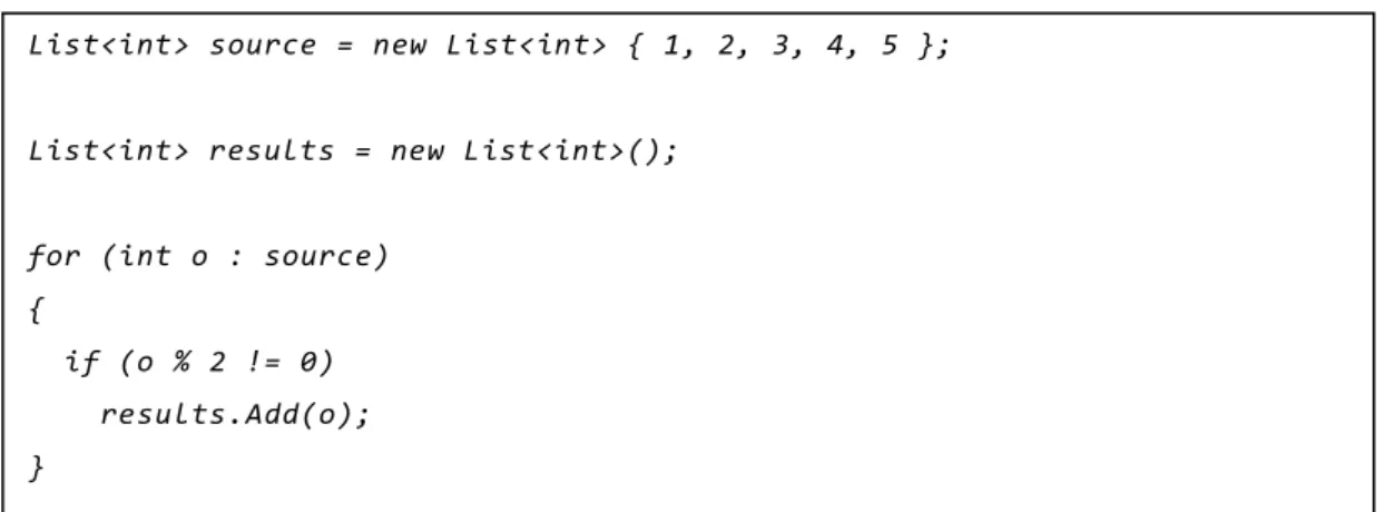
Figure 5.1 - Imperative Language Syntax 28
Figure 5.2 - Declarative Language Syntax 28
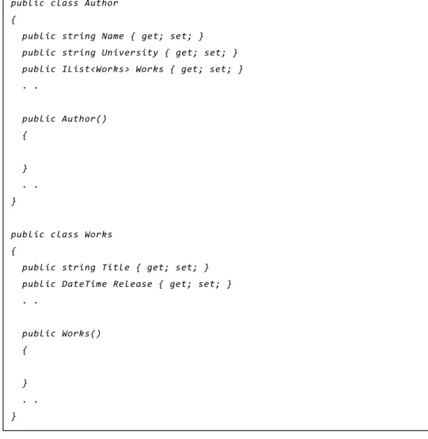
Figure 5.3 - Very Simple C# Objects 30
Figure 5.4 - Instantiating Objects Imperatively (using C#) 31
Figure 5.5 - Instantiating Objects Declaratively (using XAML) 31
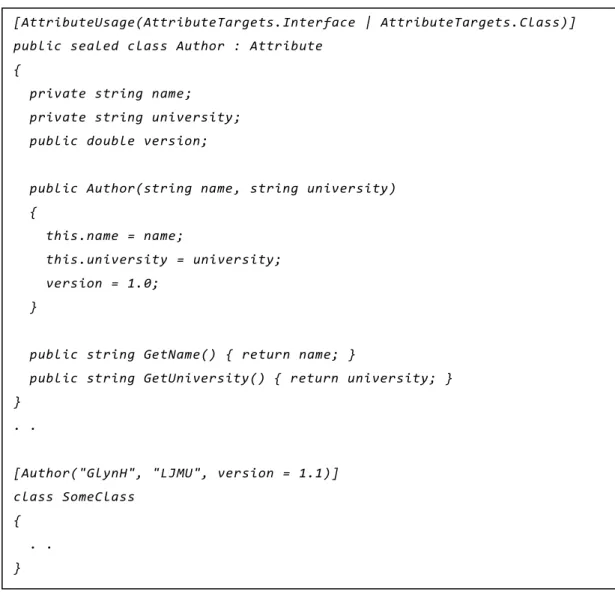
Figure 5.6 - Declaring Custom Attribute Class 32
Figure 5.7 - Reflecting Custom Attribute Class 33
Figure 7.1 - Virtualisation Management System Physical Architecture 38
Figure 7.2 - Virtualisation Management System UML Component Diagram 40
Figure 7.3 - Virtualisation Management System Object Model Diagram 41
Figure 7.4 - Virtualisation Management System Control Flow Diagram 43
Figure 7.5 - Virtualisation Management System Interface, Class & Enumeration Definitions 47 Figure 7.6 - Virtualisation Management System Imperative Syntax (using C#) 48 Figure 7.7 - Virtualisation Management System Declarative Syntax (using XAML) 49
Figure 8.1 - Virtualisation Management System Scenario Resolutions 52
Figure 8.2 - Virtualisation Management System Scenario One’s Original XAML 53
Figure 8.3 - Virtualisation Management System Scenario One’s Revised XAML 55
Figure 8.4 - Virtualisation Management System Scenario Two’s Original XAML 57 Figure 8.5 - Virtualisation Management System Scenario Two’s System Agent XAML 58
Figure 8.6 - Virtualisation Management System Scenario Two’s Revised XAML 60
Figure 8.7 - Basic DashBoard Scenario Graphical User Interface 63
Figure 8.8 - Basic DashBoard Scenario Declarative Markup 64
Figure 8.9 - Virtualisation Management System C# RequestPacket Class 65
Figure 8.10 - Virtualisation Management System C# StatusPacket Class 66
Figure 9.1 - Aims & Objectives Accomplished 70
Glossary of Terms
AJAX (Async. JavaScript & XML)API (Application Programming Interface) CCMS (Cloud Computing Management System) CLR (Common Language Runtime)
COM (Component Object Model) CPU (Central Processing Unit) CSV (Comma Separated Value) DLL (Dynamic Link Library) ETL (Extract Transform & Load) GUI (Graphical User Interface) IaaS (Infrastructure as a Service)
IDE (Integrated Development Environment) IIS (Internet Information Services)
I/O (Input/Output)
JSON (JavaScript Object Notation) MMC (Microsoft Management Console) MVC (Model View Controller)
NFS (Network File System)
OLAP (Online Analytical Processing) OLTP (Online Transaction Processing) PaaS (Platform as a Service)
QoS (Quality of Service)
RDBMS (Relational Database Management System) RDP (Remote Desktop Protocol)
RESTful (Representational State Transfer) SaaS (Software as a Service)
SQL (Structured Query Language) UML (Unified Modelling Language) VDev (Virtual Devices)
VMM (Virtual Machine Manager)
VMMS (Virtual Machine Management Service) VMWP (Virtual Machine Worker Process) VSC (Virtualization Service Clients)
VSP (Virtualization Service Providers) WCF (Windows Communication Foundation) WMI (Windows Management Instrumentation) WPF (Windows Presentation Foundation) XAML (eXtensible Application Markup Language) XML (eXtensible Markup Language)
List of Publications
This research and development has been documented, in part, within the following publications :
G.D. Hughes, D. Al-Jumeily, A.J. Hussain, “Research, Design & Development Review of the Cloud Computing Management System (CCMS)”, 6th International Conference for Internet Technology & Secured Transactions (ICITST 2011), ISBN : 978-1-4577-0884-8, Abu Dhabi, UAE, 2011.
G.D. Hughes, D. Al-Jumeily, A.J. Hussain, “Supporting Cloud Computing Management through an Object Mapping Declarative Language”, 3rd International Conference on Developments in eSystems Engineering (DeSE 2010), ISBN : 978-0-7695-4160-0, London, UK, 2010.
G.D. Hughes, D. Al-Jumeily, A.J. Hussain, “A Declarative Language Framework for Cloud Computing Management”, 2nd International Conference on Developments in eSystems Engineering (DeSE 2009), ISBN 978-0-7695-3912-6, Abu Dhabi, UAE, 2009.
Chapter One ~ Introduction
1.1.
Overview
In any complex computing system there are, amongst others, two accompanying mechanisms, a management sub-system and an underlying programmatic framework. Virtualisation is a cogent example of such a complex computing system. Virtualisation may be employed in small scale desktop environments, but it is also frequently scaled to hugely complex data centre infrastructure. In such a scenario, there may be hundreds or thousands of components and sub-components and as such, a comprehensible requirement for effective and efficient management sub-systems.
Supporting such management sub-systems are typically programmatic frameworks, ranging from low level to high level Application Programming Interfaces (APIs). Any proprietary management tools are typically designed atop these APIs while third-party developers may access the programmatic frameworks to develop bespoke applications and services. Alongside developers there are also, with growing frequency, automatic / autonomic systems that strive to augment or replace human interaction.
When designing APIs to support both humans and automatic / autonomic systems there is a desire to provide a readily understandable programmatic environment. With the complexity inherent in utilizing an imperative language there are considerable advantages to be gained in utilizing a more declarative language, especially as object mapping allows both humans and automatic / autonomic systems to specify considerable amounts of syntactically complete, object oriented, imperative code without actually writing any imperative code.
1.2.
Motivation
The evolution of the internet into an application and service oriented platform has resulted in the growth of cloud computing as well as the underlying data centre infrastructure. The use of virtualisation in hugely complex data centre infrastructure has seen comparable growth and today there are few physical servers directly hosting cloud computing applications and services, they are now wholly virtualised!
Similarly, the evolution of the database from the relatively light weight Relational Database Management System (RDBMS) through data warehousing to hugely complex, bespoke big data applications has placed differing yet no less demanding requirements on the use of virtualisation in hugely complex data centre infrastructure.
While the problem of managing virtualisation technology is relatively new, there are historical parallels in any complex infrastructure. A cogent example can be found in an electricity grid, where power is not only produced, distributed and consumed, but the amount of power required, by whom and where is tracked, analysed and used to anticipate and thusly balance future supply and demand.
The same management problems are now directly relevant to virtualisation technology as the enormous material and running costs of hugely complex data centre infrastructure along with global initiatives in green computing require that hardware and software resources be effectively and efficiently managed.
1.3.
Research & Development Question
Motivated by these issues, the key research and development question that this thesis will attempt to address is as follows (in the author’s original wording), “Can an object mapping declarative language framework effectively and efficiently facilitate both humans and autonomic systems in the setup and management of virtualised systems, their resources and their infrastructure?”
1.4.
Aims & Objectives
The aims of this study are to design, develop and verify a framework that supports virtualisation management using an object mapping declarative language to store the system schema in play at any specific moment. The declarative language should form the interface between the framework and both humans and automatic / autonomic systems and it should express its functionality through an underlying imperative language.
To help achieve these aims, the objectives of this study are as follows :
1. Explore key computing infrastructure that rely heavily on virtualisation technology. 2. Investigate virtualisation technology in terms of its functionality and management.
3. Investigate programming paradigms that may serve to satisfy the anticipated development to come. 4. Design and implement a programming framework that satisfies the framework
requirements using the appropriate programming paradigms.
5. Verify the framework in terms of its ability to effectively and efficiently manage the key computing infrastructure.
1.5.
Contributions
toKnowledge
The customary use of an object mapping declarative language has been within Graphical User Interface (GUI) designers whereby a declarative language, such as eXtensible Markup Language (XML), is stubbed out by the designers following a drag and drop GUI design session. A one-to-one relationship persists between the declarative language and its visual equivalent in the designers and the declarative language can be thought of as the designers default data storage format.
The story doesn’t end their though as the very same declarative language can also have a one-to-one relationship with an imperative assembly, typically object oriented in nature. Indeed, one of the key characteristics of the object oriented paradigm is the concept of composition, allowing any type to be embedded within others. A declarative (XML alike) language uses a nested hierarchy structure to embed elements within others in much the same way. So much so that an imperative assembly may be specified entirely using a declarative language, a mechanism known as object mapping.
This results in an interesting situation in which designers and developers can now specify considerable amounts of syntactically complete, object oriented, imperative code without actually writing any imperative code. This allows problem solving the problem domain to remain at the forefront without the distractions inherent in boilerplate coding, typically much more of an issue when working with imperative code.
The key contributions to knowledge can thusly be summarised as follows :
1. Encapsulating the key virtualisation management operations in a readily extensible imperative framework. 2. Exposing the imperative framework’s capability through a declarative language.
3. Providing a mechanism by which both humans and automatic / autonomic systems may employ the declarative language interactively.
1.6.
Research & Development Activity
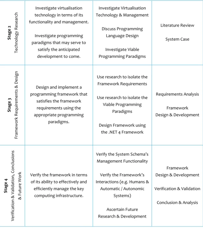
The aims of this study dictate the research and development strategy and the various stages that constitute that strategy. The objectives in turn, dictate the key tasks and the methodologies that are required to address the research and development question considered by the study. Figure 1.1 shows a research and development map identifying the stages, the corresponding objectives, the key tasks and the methodologies employed.
STAGE OBJECTIVES KEY TASKS METHODOLOGY
S tag e 1 Requ ir e me nts R e se arc h
Explore key computing infrastructure that rely heavily
on virtualisation technology.
Explore
Cloud Computing Systems
Explore Big Data Systems
. . ascertain the relationship with Virtualisation
Technology
Literature Review
Figure 1.1 - Research & Development Map
1.6.1.
Ethical Considerations
All research and development activity contained within this thesis is purely technological in nature. There is no direct or indirect handling of any individual’s personally identifying data or demographics concerning any group of individuals, vulnerable or otherwise.
S tag e 2 Tec hno lo gy R e se arc h Investigate virtualisation technology in terms of its functionality and management.
Investigate programming paradigms that may serve to
satisfy the anticipated development to come.
Investigate Virtualisation Technology & Management
Discuss Programming Language Design Investigate Viable Programming Paradigms Literature Review System Case S tag e 3 Fr am e w o rk Re qu ir e me nts & D e sig n
Design and implement a programming framework that
satisfies the framework requirements using the
appropriate programming paradigms.
Use research to isolate the Framework Requirements
Use research to isolate the Viable Programming
Paradigms
Design Framework using the .NET 4 Framework
Requirements Analysis Framework Design & Development
S tag e 4 Ve rifi cat io n & Va lid at io n, C o n clu sio ns & F u tu re W o
rk Verify the framework in terms of its ability to effectively and efficiently manage the key
computing infrastructure.
Verify the System Schema’s Management Functionality
Verify the Framework’s Interactions (e.g. Humans &
Automatic / Autonomic Systems)
Ascertain Future Research & Development
Framework Design & Development
Verification & Validation
1.7.
Thesis Structure
In terms of its chapters, the thesis’s structure follows the stages as shown in the research and development map : Requirements Research (comprising chapters 2 & 3)
Technology Research (comprising chapters 4 & 5)
Framework Requirements & Design (comprising chapters 6 & 7)
Verification, Validation, Conclusions & Future Work (comprising chapters 8 & 9)
Chapter 2 is the first of two requirements research chapters concerned with establishing the necessity of and requirements for virtualisation technology. The chapter contains an analysis of the characteristics that cloud computing systems exhibit. The chapter then continues with a discussion of the principle architecture, underlying technology and service models that existing and emerging cloud computing systems contain. As the first of two scenarios for virtualisation, it is important to determine the requirements that are expected of virtualisation technology when supporting cloud computing systems / infrastructure.
Chapter 3 is the second of two requirements research chapters concerned with establishing the necessity of and requirements for virtualisation technology. The chapter contains an analysis of the concepts and characteristics that big data systems exhibit. The chapter then continues with a discussion of the technology stack, including Online Transaction Processing (OLTP), Extract Transform & Load (ETL), Online Analytical Processing (OLAP), Data Analytics and Reporting & Virtualisation. As the second of two scenarios for virtualisation, big data systems / infrastructure have somewhat differing but no less important requirements that are expected of virtualisation technology.
Chapter 4 is the first of two technology research chapters taking a comprehensive yet concise look at virtualisation technology. The chapter examines how hypervisors actually operate as well as the existing and emerging management mechanisms. Emerging from this knowledge, are a set of well-defined services and operations (i.e. the things that hypervisors can actually do). It is this knowledge that will serve to inform the core functionality of the VMS.
Chapter 5 is the second of two technology research chapters that primarily concerns the relationship between the imperative and declarative programming language. While they strive for a differing set of characteristics, internally a declarative language can map to an imperative language. This combines the separation of concern inherent in declarative markup with the fine grain control inherent in imperative code. The chapter then continues with a discussion of two mechanisms that achieve this, object mapping and attribute oriented programming.
Chapter 6 combines the knowledge gained from the previous research chapters to identify the virtualisation management operations that the VMS will need to support. The chapter will ultimately define a concise collection of functional and non-functional requirements along with the required external interaction with both humans and automatic / autonomic systems.
Chapter 7 is the first of two chapters that explore the VMS design and development. The chapter begins by designing the physical architecture, software components, imperative (and by virtue, declarative) object model and operating principle of the VMS. This chapter then continues by exampling the object mapping declarative language in situ along with the various supporting mechanisms that allow the VMS to provide its core functionality.
Chapter 8 is the second of two chapters that explore the VMS design and development whilst concurrently verifying and validating the VMS core functionality. The chapter aims to bring the VMS to life by way of two scenarios, with each scenario demonstrating some core functionality as it attempts to solve specific problems that are typical of the VMS operating domain. The chapter then continues by demonstrating the three key areas of external interaction that the VMS supports (namely the hypervisor, the human and the automatic / autonomic plug-in) and by virtue, revealing the key findings of VMS and identifying areas of ongoing design and development that will inform any future work.
Chapter 9 presents the research and development findings of the thesis in terms of the aims & objectives accomplished, the contributions to knowledge, the research and the development constraints. The chapter then wraps up the thesis with a discussion of the possible / likely future research and development concerns, with each significant component / sub-component of the VMS containing areas that could be potentially augmented or extended.
Chapter Two ~ Cloud Computing
2.1.
Overview
The term cloud computing is a moniker for a computing model that has existed for some time but is only now evolving to the point where it is becoming commonplace. Broadly speaking, cloud computing describes a computing model in which information technology systems are accessed purely over the internet, thusly removing the requirement to setup software and servers locally [1] [2].
The internet based nature of cloud computing means that software becomes a service (actually, SaaS or “Software as a Service” is a whole subset of cloud computing [3]) that may be freely available to the public or available only to a specific group / institution. The following key characteristics are strongly representative of cloud computing :
Availability.
o The vast majority of data and processing is typically hosted server side so cloud applications can be accessed from any device connected to the internet. In addition the level of redundancy that cloud computing brings across applications, servers and data centres ensure that cloud applications are always online [3].
Scalability.
o Every cloud application can be hosted alongside numerous others in centralized servers and data centres. By automatically provisioning and sharing resources, such as processing, memory and bandwidth, a data centre’s resources can by optimized to respond to and even anticipate peak working periods [4].
Security.
o The security of user’s data is typically more elaborately protected due to the centralization of data within servers and data centres that have hive like security concerns beyond those of any individual cloud applications and of any less centralized, locally hosted applications [3].
Maintenance.
o Depending on the specific role of cloud applications, there is likely to be little or no maintenance activity expected of users. Any such maintenance activity is the responsibility of the owners of the data centre and is typically rolled in to the data centre’s service level agreement [4].
Performance.
o In much same way scalability can be achieved through optimizing a data centre’s resources, so too can the outright performance of cloud applications [4]. In addition, a data centre by its very nature will be capable of considerably more processing than any servers that host locally.
Costs.
o The costs to users may be reduced as cloud computing providers operate the entire architecture and users need only have access to said architecture via the internet [3]. Costs at most are restricted to service subscriptions, which are frequently known under the umbrella term, utility computing [5].
2.2.
Principle Architecture & Underlying Technology
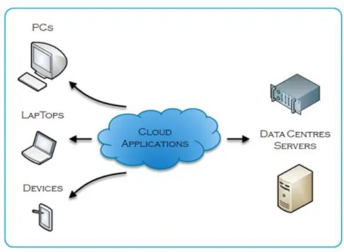
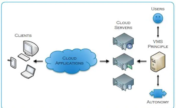
The principle architecture of cloud computing is largely unremarkable in that it works on the current internet infrastructure [1] [6]. Figure 2.1 shows this principle architecture, illustrating both the client side and server side components. From any client side perspective, the cloud applications are delivered as a service. The result is that the cloud servers that host the cloud applications are largely unseen from the client side perspective [3].
Figure 2.1 - Cloud Computing Principle Architecture
As such, the common architectural infrastructure of cloud computing can be summarised as follows :
Both the logical and physical cloud computing model is a strong instance of the long standing client server model. Well established internet technologies, such as TCP/IP and HTTP, satisfy cloud computing’s core requirements. More recently adopted internet technologies now facilitate rich application development, including :
o MVC (Model View Controller) server side web applications.
o RESTful (Representational State Transfer) web services.
o WebSockets fully duplex communications.
o JSON (JavaScript Object Notation) data modelling & storage.
The novel aspects of cloud computing revolve around scalability and include revised usage patterns concerning both the hardware and software components [6]. Every cloud application is hosted in centralized data centres that provide high performance processing, redundancy through hardware clustering and multiple backbone internet connections, high availability afforded by backup power supplies and the economic sustainability of sharing such resources and capabilities [2] [7].
Within these centralized data centres, individual servers are tasked with specific roles and responsibilities including web servers, database servers, content management servers, backup and recovery servers and the all-important management / load balancing servers. A collection of servers may also be clustered together so as to better facilitate the advantages as discussed in the previous paragraph [6].
2.3.
Service Models
There are three generalised tiers to the capability and service that cloud computing solutions may provide. They are tiered by virtue of their level of logical abstraction. At the top end we have the ready for market applications that, from the client side perspective appear as any locally hosted application would in the long standing client server model. At the bottom end we have the raw infrastructure components upon which servers, applications and services are hosted.
When these tiers are provided at costs, they are commonly called utility computing and the provision of cloud computing services becomes subscription based [5]. The utility computing approach has the advantage of a low or even zero initial setup costs and cloud applications distributed through utility computing are simply supplied on a “pay as you go” basis.
2.3.1.
SaaS
(Software as a Service)The SaaS model is the most significant subset of cloud computing and represents its most core principle, which primarily concerns the high availability of applications and services that are hosted in centralized data centres. These applications and services range from the bespoke developed variety to the commercially available and dynamically customizable variety [3].
2.3.2.
PaaS
(Platform as a Service)PaaS is an extension of the SaaS model. The PaaS model exposes a complete set of tools and controls to support the entire software development life cycle. This takes place without the need for any development tools to be present on the client side computer. Effectively the developers / authors writes applications on the server side directly and PaaS manages the entire process through well-defined workflows [8].
2.3.3.
IaaS
(Infrastructure as a Service)The IaaS model is simultaneously the simplest and also the most extreme form of cloud computing. It exposes a complete computing infrastructure, typically physical servers and networks that may support applications, data storage and virtual servers and networks [9]. The engineers have considerable autonomy in how the servers are setup and managed.
2.4.
Cloud Computing’s Positioning
There is a grey area between the long established eCommerce application and the cloud application. A cogent example might include long standing online services such as HotMail (now Outlook.com). HotMail has always been web based, data driven, available globally with 99% uptime, scalable to foreseeable usage requirements and it has always been a freely available online service. So by industry standards, does it qualify as a cloud application? Probably yes, but the genesis of HotMail’s design and development was largely solitary from other online services and only much later on was it incorporated into the wider Microsoft Live family, which can be considered a true first generation collection of cloud applications.
There is also a grey area concerning cloud computing infrastructure. What is the difference between a group of well-managed, high performance servers and a data centre specifically designed to operate cloud computing solutions? As before, the actual hardware components are typically comparable, but with the data centre simply having more hardware resources. The most significant distinction though is that cloud computing brings with it a set of service models that define and manage how users interact with cloud applications [1] [6].
It is thusly not unreasonable to determine that cloud applications are either designed from scratch to exist within a cloud computing infrastructure or are scaled up versions of existing online services that may or may not have already exhibited characteristics typical of cloud computing.
2.5.
Relationship
withVirtualisation
Virtualisation, in respect of cloud computing, primarily involves consolidation, whereby numerous, typically less capable physical servers are replaced by fewer, more capable physical servers [10]. This reduces costs as less hardware resources are required. However, it is not favourable to fully consolidate host operating systems so each must be converted to a guest operating system. In this guise, many virtual servers can execute on a single physical server.
The commercial growth in the use of virtualisation has tightly mirrored cloud computing [7]. This is not surprising as top level virtualisation requires the centralized deployment and management of systems and resources, a definition that is certainly descriptive of cloud computing [10]. The SaaS model abstracts information technology in a way comparable to the abstraction of enterprise servers and software in virtual servers [3]. Recent advances in available hypervisors have made virtualisation very attractive to industry and most if not all cloud computing architectures are now based on virtual servers rather than physical servers [11] [1].
2.5.1.
The Management Problem
By definition, the use of virtualisation as the basis of a cloud computing architecture implies a considerable number of virtual servers, typically many more than the physical servers upon which they execute [6]. This poses a system and resource management problem, especially in situations where virtual servers are constantly being instantiated, allocated work (swapping in), de-allocated work (swapping out) and then destroyed. Indeed, many operations might be performed on a cloud computing architecture, including :
Swapping In & Swapping Out.
o Generally to distribute work during any bottlenecks or peak work periods [4]. Scaling Up & Scaling Down.
o A less aggressive case of swapping which virtual servers are allocated more resources and vice versa [4].
Redundancy & Recovery.
o To provide an always online guarantee and to ensure that service and data is readily recoverable.
Typically, cloud applications themselves are not aware of these changes [1]. This is not only wise, but also common practice in many computing technologies; software should not normally care about the hardware resources on which it executes. However, there is a case to allow cloud applications to specify their preferred operating environments and to describe their own projected requirements and characteristics.
Various software vendors have developed proprietary solutions that manage cloud computing infrastructure and more specifically the virtual servers upon which they execute. The AutoPilot system was developed internally at Microsoft to manage the initial growth and operation of the aforementioned Microsoft Live family [12]. However, it is ostensible that the AutoPilot system focuses on top down management and thusly makes assumptions as to the specific preferred operating environments of its cloud applications [12]. Similarly the OpenStack AutoPilot system which is developed by Canonical alongside their flagship Ubuntu Linux operating system has seen considerable growth as an IaaS platform [13]. However, much like Microsoft’s AutoPilot system and a representative characteristic of an IaaS platform, there is still a focus on top down management.
2.6.
Summary
This chapter began by identifying some of the key characteristics that cloud computing systems exhibit, these characteristics would later on in the chapter serve to specify the operations that virtualisation would need to provision in support of cloud computing systems. This chapter has also discussed the principle architecture, underlying technology and service models that existing and emerging cloud computing systems contain and critically, these aspects have been found to closely relate to virtualisation technology.
Chapter Three ~ Big Data
3.1.
Overview
The term big data is a relatively recent moniker that refers to a set of both evolutionally and revolutionary developments in the field of data analytics. It concerns large data sets that are so substantial in size and complexity that traditional data processing mechanisms are inadequate. Indeed, the long established Relational Database Management System (RDBMS) along with similarly long established data reporting and visualisation tools perform poorly when handling big data solutions [14].
The architecture of big data solutions thusly combines both existing and emerging data mechanisms to bestow a previously unseen ability to manage huge sets of disparate data and more importantly, to derive timely analysis that facilitates both tactical and strategic decision making [14]. This is commonly achieved through massively parallel processing which in turn is achieved through distributed computing environments. The following key characteristics (colloquially known as the three V’s) are strongly representative of big data [15] :
1. Volume.
o How much data is generated and processed? 2. Velocity.
o How quickly is the data generated and how quickly must it be processed? 3. Variety.
o What is the data’s nature and its format, ranging from traditional structured data to highly un-structured data? This is perhaps the first significant departure from the long established RDBMS, which are typically designed to manage traditional structured data only.
These initial three V’s provide an insight into the problems of managing such huge sets of disparate data, but they could just as easily be applied to non big data solutions. Thusly, two additional V’s have recently been defined to help describe the hugely complex nature of big data [15] :
4. Veracity.
o How accurate is the data? Critically, the accuracy of any analysis is highly dependent on the accuracy of the original data and any resulting calculations may become totally unviable in the presence of erroneous or missing data.
5. Variability.
o In what ways does the meaning of the data change? Frequently confused with variety, variability is especially problematic when dealing with natural language as meaning changes constantly due to context (e.g. serious vs sarcastic statements).
While it may be convenient to classify big data using these characteristics, they can be frequently misleading and overly simplistic (e.g. big data solutions may involve huge volumes of traditional structured data or they may involve a tiny amount of highly un-structured data and while both are complex problems, they require quite distinct solutions) [14].
3.2.
Technology Stack
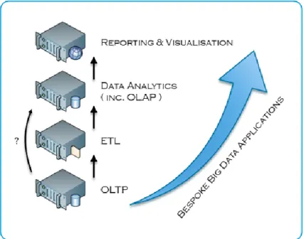
In combining both existing and emerging data mechanisms, a big data technology stack may be logically extrapolated [14]. Figure 3.1 shows the key stages in such a big data technology stack, illustrating both the relative positioning and the interactions that exist between such data mechanisms. Critically, while each stage may be employed in the sequence shown, it is not uncommon for one or more stages to be skipped. Indeed, as alluded to in Figure 3.1 there are analytical extensions to Structured Query Language (SQL) that allow for Online Analytical Processing (OLAP) style queries to be executed directly atop Online Transaction Processing (OLTP) solutions, bypassing the Extract Transform & Load (ETL) process entirely [16].
Figure 3.1 - Big Data Technology Stack
3.2.1.
OLTP
Even before the emergence of big data, long established OLTP solutions, commonly designed atop RDBMS and utilizing the entity relationship model, frequently grew to a massive scale. Entire data centres to this day, remain dedicated to their continuing operation and management. One needs only to consider the OLTP solutions supporting corporations such as Amazon and eBay. It is thusly not perverse to state that OLTP solutions require constant monitoring and management of their resource usage and that they are particularly susceptible to peak working periods [17].
Given this systemic knowledge, OLTP is a suitable case for virtualisation on its own. But, in the context of big data, OLTP represents one of the primary data sources and thusly helps form the first stage in the big data technology stack.
3.2.2.
ETL
The ETL process is the primary mechanism by which a data warehouse is initially constructed. Additionally, the process is typically re-run on a schedule such as weekly, quarterly, annually, so as to populate the data warehouse with any newly available data [18].
The process begins with the extraction of data from one or more data sources such as RDBMS, SpreadSheets, Plain Text and Comma Separated Value (CSV). Next, the transformation of data ensures that it conforms to a single structure without losing any of its underlying semantics. Finally, the loading of data into the data warehouse though an appropriate analytical data model (e.g. the multi-dimensional vs the tabular model). Critically, each of these three stages are distinct and may take considerable processing, memory and data storage, so it is common for suitably designed work flows to execute the three stages concurrently. This allows data to progress from one stage to the next as a stream without having to wait for the entire block of data to pass through the previous stage [18].
Thusly, in the context of a big data, ETL represents the transition of data from data sources to data warehouses and thusly helps form the second stage in the big data technology stack.
3.2.3.
OLAP
As with OLTP, long established OLAP solutions also pre-date big data. Based around the data warehouse and primarily utilizing the multi-dimensional model, the role of OLAP is quite distinct from OLTP. Whereas the entity relationship model is designed to minimize data redundancy and support large numbers of relatively tiny but concurrent transactions, the multi-dimensional model is designed to process large amounts of data in lengthy transactions to which only a few users have access rights [19]. These users are typically business executives who use OLAP to inform in strategy and planning decisions.
As much of the work performed by OLAP is concerned with aggregating data when the ETL process must populate the data warehouse with any newly available, it is not perverse to state that OLAP solutions experience periods of relatively low resource usage and only on a set schedule, do they suddenly require extra processing, memory and data storage [19].
3.2.4.
Data Analytics
One emerging distinction between OLAP and data analytics is the extension of access rights to users who are non-business executive. With data analytics, users who work on tactical rather than strategic decision making may leverage real-time analysis to inform business operations within their operational area. In this way, data analytics can be seen to move historically back office processing to the front office [20]. Many corporate business applications, such as Microsoft Excel, are rapidly incorporating the client side functionality necessary to interact with data analytics. In addition the field of data analytics has grown to the point where it may effectively envelop OLAP [21].
3.2.5.
Reporting & Visualisation
The developer’s interface to a database solution (be it OLTP or OLAP) is typically complex and not in any way friendly to non-technical users. To enable such users to view data in a logical and concise way, data reporting systems exist that provide simple operations, such as filtering and sorting, along with results displayed in tables and graphs. While these systems have been deployed alongside database solutions for a long time, they may also be employed in displaying results from data analytics solutions [22].
As the complexity of data grows, so too does the necessity to view data effectively. Visualisation is an emerging technology that offers a more interactive, animation oriented interface than data reporting systems. They are typically designed atop dedicated visualisation Application Programming Interfaces (APIs) or even fully established 3D APIs such as OpenGL and DirectX [23]. These APIs are of special interest as they may require an additional virtualisation technology, that of graphics virtualisation.
3.2.6.
Bespoke Big Data Applications
Using the big data technology stack as shown in Figure 3.1 we can see that bespoke big data applications are pervasive across every key stage. As an emerging technology, big data is highly dynamic and defining its scope may be unproductive. Thusly, any big data applications are likely to have been designed and developed to bespoke requirements.
Any big data solution can also be thought of as being horizontally or vertically aligned in scope when considering the big data technology stack. A horizontally aligned solution would likely focus in depth on fewer stages (e.g. taking the results from the reporting & visualisation stage). In contrast, a vertically aligned solution would likely interact with more stages but perhaps not in as much depth (e.g. taking only pertinent data from each stage).
3.3.
Relationship
withVirtualisation
Many of the key stages as shown in Figure 3.1 are implemented by the big three’s (e.g. Oracle, IBM & Microsoft) flagship enterprise servers. When taking Microsoft as an example, the SQL Server platform supports OLTP, ETL, OLAP & Reporting. The newly acquired R Server platform performs data analytics and visualisation with bespoke big data applications on the platform’s immediate road map. For years now Microsoft has closely tied their enterprise servers with their server operating system’s native capabilities, including technologies such as Always-On Failover Clustering [24]. Always-On requires multiple instances of the enterprise servers to be hosted in a distributed environment typically designed atop virtual servers. In such a scenario, enterprise servers are not only ideally suited to virtualisation technology but in fact desire it.
In much the same way that most if not all cloud computing architectures are now based on virtual servers rather than physical servers, the same can said for big data architectures. Staying with Microsoft as an example, the growth of Azure has been astonishing and every enterprise server that Microsoft offers now has some degree of Azure integration. Azure in turn, is almost entirely based on Microsoft’s own virtualisation platform, known as Hyper-V. Thusly whenever big data architectures are running atop Azure, they are by definition running atop virtual servers.
3.3.1.
The Management Problem
As discussed in Section 3.1, processing large data sets, be they structured or un-structured is inherently preferable through distributed computing environments. As such, the processing tasks of big data solutions (e.g. capture, organise, integrate, analyse & act) are typically processed independently yet in parallel [25]. MapReduce processing is a cogent example of this scenario; as the Map and Reduce processes are independent, they can allowed to compete constructively for resources depending on the processing payloads each has at any one time and the current level of contention amongst the hosting virtual servers [25]. Virtualisation technology thusly bestows big data solutions with the ability to scale dynamically to unexpected payloads no matter which tasks may trigger the payload. Despite processing occurring independently yet in parallel, there are some work flow considerations in big data architecture, including :
Scheduling.
o Be it a schedule defined by users, as is the case with the loading of data in ETL or a wholly automated schedule, as is typically the case with the optimization and aggregation in OLAP.
Prioritising.
o With such huge sets of data being processed, there are logically going to be subsets of data that must be processed first, either to support follow on data processing or to answer more urgent queries as posed by users.
3.4.
Summary
Mirroring the previous chapter, this chapter began by identifying some of the key characteristics that big data systems exhibit, these characteristics would later on in the chapter serve to specify the operations that virtualisation would need to provision in support of big data systems. This chapter has also discussed the technology stack, identifying the key stages that existing and emerging big data systems contain and critically, as with the previous chapter, these aspects have been found to closely relate to virtualisation technology.
Chapter Four ~ Virtualisation
4.1.
Overview
The previous two chapters have established the positioning of virtualisation as one of the key technologies employed in both cloud computing and big data solutions. Following a general discussion of the various types of virtualisation that are available, this chapter moves on to catalogue the history of hypervisors and explore the concepts that underpin the technology before concluding with a case study into one of the most common hypervisors in industry today along with an investigation into the existing and emerging management mechanisms.
4.2.
Types
of
Hypervisors
There are various types of virtualisation available with some representing the high level or primary layers and some representing the nested or secondary layers. While it is both undesirable and unnecessary to describe every single type, the following are representative of the primary layers :
Hardware Virtualization.
o Allows multiple operating systems to run on the same physical machine at the same time. The physical machine is logically partitioned into multiple virtual machines and any hardware resources, such as memory and processing, are shared between them. The virtual machines are thusly software representations of the physical machine, yet they are able to perform the same tasks [11] [26].
Application Virtualisation.
o Allows for an application to be encapsulated inside its own miniature operating system “bubble” and then deployed to a target operating system without any notion as to the runtime environment of that operating system. A cogent example of application virtualisation is the Wine Platform which allows Windows applications to run on Linux without necessarily being in any way aware [27]. An application virtualisation platform must thusly replace some or all of the target operating system’s runtime environment and is responsible for translating any Input/Output (I/O) requests that the encapsulated application might make [11] [26].
Storage Virtualisation.
o Serves to combine physical storage resources into a single logical storage resource. Any applications accessing the virtualised storage have no notion of how and where the data is actually stored and retrieved [26] [28]. A cogent example of storage virtualisation is the Network File System (NFS) which may encapsulate physical storage resources from disparate and even incompatible platforms (e.g. the native file systems of Windows and Linux, NTFS and EXT4 respectively).
Network Virtualisation.
o A physical network may be virtualised in much the same way a physical machine may be and in data centres, both networks and machines are typically virtualised together in one operating environment. There are two general forms of network virtualisation, external and internal. External describes a scenario in which one or more physical networks are encapsulated then partitioned into as many logical networks as are required [29]. Internal describes a scenario in which a single physical machine may host one or more wholly software driven networks, typically to create a virtualised network between the guest operating systems that are running on the host operating system [29].
4.3.
History
of
Hypervisors
Virtualisation as a computing concept has existed for a long time in high performance computing, but in common place computing it is only since the mid-noughties that hardware virtualisation has been steadily transforming both server side and client side computing architecture. The previous generations of 32-bit hardware (x86-32) were designed to run a single operating system. This scenario was perfectly acceptable for desktops / workstations. However, when considering servers, there was a strong possibility that unless the operating system was constantly busy, considerable portions of the hardware resources, such as memory and processing, would not being fully utilized. Virtualization technology was designed to run multiple operating systems (called virtual machines) on a single physical machine [11]. The virtual machines share the hardware resources of the single physical machine and each virtual machine can run any operating system that is compatible with the underlying hardware. While various virtualisation management tools were available for x86-32, most would only run as an application on top of the single operating system resulting in software mode virtualisation [10] [11].
With the release of the new generations of 64-bit hardware (x86-64), hypervisors took a decisive shift towards deeply integrated hardware virtualisation [30]. The primary benefits of which are greatly enhanced performance along with feature support that is only possible through direct access to the physical machine’s hardware resources. The principle advancements in x86-64 virtualisation concern Central Processing Unit (CPU) technologies such as Intel’s VT-x [31] and AMD-V [32].
4.4.
Hypervisor Technology
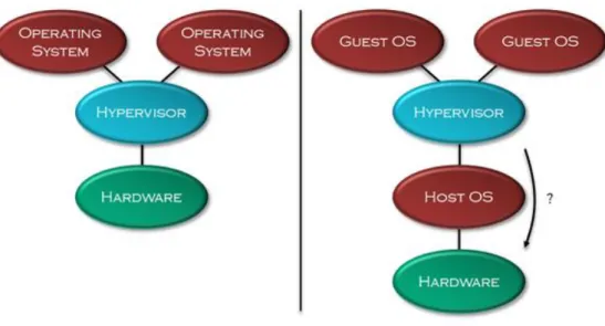
Broadly speaking, there are two categories of hypervisor technology in existence, type-one and type-two [33]. While they provide comparable functionality to users of virtualisation, they differ considerably in their underlying operating principle. Figure 4.1 shows the principle distinction between each hypervisor technology.
Figure 4.1 - Hypervisor Technology
4.4.1.
Type-One
(Native Hypervisors)The type-one hypervisor itself is the sole host operating system running on the physical machine and has exclusive access to the physical machine’s hardware resources. In type-one hypervisors the distribution of these hardware resources amongst the guest operating systems is performed solely by the hypervisor [33].
There are numerous type-one hypervisors available, two that are commonly employed are :
Microsoft Hyper-V [34]
o Proprietary 64-bit hypervisor developed by Microsoft for the Windows Server 2008 onwards.
o Hyper-V is primarily aimed at enterprise servers, ranging from the Small to Medium Enterprise (SME) to the complete data centre solution.
VMware ESXi [35]
o Proprietary 64-bit hypervisor developed by VMWare.
o ESXi is similarly aimed at enterprise servers but differs in that it doesn’t integrate with any operating system directly, instead employing its own base Linux Kernel.
4.4.2.
Type-Two
(Hosted Hypervisors)The type-two hypervisor runs on another host operating system and must share the physical machine’s hardware resources with any other applications. In type-two hypervisors the hardware resources are typically abstracted so the guest operating systems are unaware of the underlying host operating system [33].
Conversely, as alluded to in Figure 4.1 and discussed in Section 4.3 recent developments in hardware virtualisation have allowed guest operating systems in type-two hypervisors to directly access the physical machine’s hardware resources in much the same way as they would in type-one hypervisor. The distinction between the two can thusly be frequently misleading and overly simplistic [36]. In addition, para-virtualisation has also allowed type-two hypervisors to emulate the virtualisation characteristics in type-one hypervisors.
Similarly, there are numerous type-two hypervisors available, two that are commonly employed are :
Oracle VirtualBox [37]
o A 32 / 64-bit hypervisor developed by Oracle, freely licensed under the GNU General Public License. o VirtualBox targets a wide range of platforms including servers, desktops and embedded systems.
VMware WorkStation & Player [38]
o Proprietary 32 / 64-bit hypervisor developed by VMWare.
o WorkStation & Player both use the same underlying core with WMware Player being freely available.
4.5.
Operation
of
Hypervisors (Hyper-V Case Study)
Hyper-V is Microsoft’s own flagship virtualisation platform. It has been available to users through various editions of the Windows Server operating system since 2008. Significantly, a wholly internal, bespoke version of Hyper-V serves as the underlying operating system of Azure.
Hyper-V is designed using the micro-kernel architecture. This design places the proprietary device drivers in each virtual machine and the virtualization stack is housed by a unique virtual machine whose primary role is to setup, deploy and manage a Hyper-V solution. This allows for ease in isolating individual virtual machines while reducing the possible attack surface. In contrast, VMware ESXi is designed using the monolithic-kernel architecture, meaning that the proprietary device drivers and virtualization stack are placed within the hypervisor alone. This allows for ease in moving individual virtual machines while consolidating the proprietary device drivers.
When the necessary virtual machine drivers and services are installed on the guest operating system, Hyper-V delivers performance approaching that of a host operating system running on physical hardware. This is achieved through Hyper-V virtual machine client code, also known as Hyper-V enlightened I/O enabling direct access to the Hyper-V virtual machine bus, bypassing any device emulation. Both Windows Server 2008 R2 and Windows 7 onwards support Hyper-V enlightened I/O through the installation of Hyper-V Integration Services. [39]. Hyper-V Integration Services are also available for other client operating systems including several Linux distributions [40].
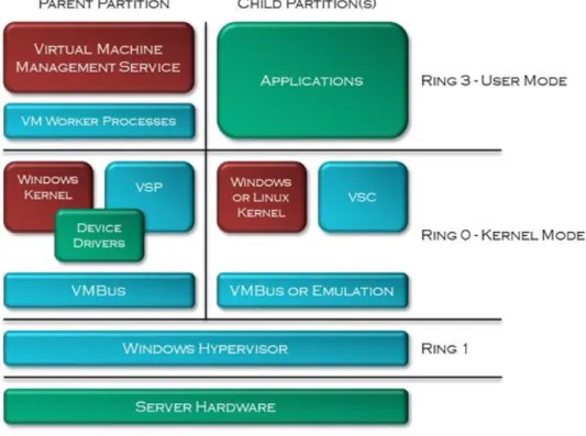
Figure 4.2 shows the key components in a typical Hyper-V deployment. Note that there would typically be more than one child partition and that each child partition may or may not host a Hyper-V enlightened I/O aware operating systems. When this is not the case, the Hyper-V virtual machine bus runs in emulation mode.
Figure 4.2 - Hyper-V Technology Stack
4.5.1.
Partitions
Hyper-V supports isolation between the guest operating systems through partitioning with each partition being a logical unit of isolation, supported by the hypervisor, in which the guest operating systems execute. A partition consists of virtual memory address space, virtual processors, worker processes and communication mechanisms. The virtual memory address space of a partition is mapped to the physical memory address space of the physical hardware. There are two types of partitions in Hyper-V, the parent partition and the child partition. Typically, a Hyper-V solution contains one parent partition and one or more child partitions [39] [41].
The parent partition is the first partition in a Hyper-V solution. Although it is technically a virtual machine, it has unique functionality. The parent partition owns all the resources not directly owned by the hypervisor and it manages the creation and operation of the child partitions. It controls access to any shared resources and defines whether they can be shared by the child partitions or restricted to a single child partition. The parent partition is in responsible for power management, devices drivers, plug-and-play and physical hardware events such as hot-swapping [39] [41].
The child partitions are software emulations of physical hardware. As such, they don’t have direct access to any physical hardware and thusly are virtual machines in the purest sense of the term. Every child partition sees see the exact same base virtual hardware, known as Virtual Devices (VDev) and extra hardware can be added to the VDev such as virtual hard disks, network cards and optical disks. As VDev do not actually exist, requests to them are directed through the VMBus to the parent partition, which facilitate the request against the physical hardware [39] [41].
4.5.2.
VSP
(Virtualization Service Providers)& VSC
(Virtualization Service Clients)The VSP are kernel-mode, software components that run on the parent partition and handle the I/O requests that support the child partitions. The VSP provides this I/O interface via the VMBus to one or more VSC. VSP also communicate directly with the physical hardware via the windows driver stack and proprietary device drivers to facilitate system wide I/O requests using an Application Programming Interface (API) called HyperCall [39] [41].
The VSC are kernel-mode, synthetic device drivers that run on the child partitions. The VSC utilize the physical hardware that has been provisioned by the corresponding VSP in the parent partition and communicate across the VMBus to the VSP to invoke the child partitions I/O requests. Critically, the entire process is unseen to the guest operating system [39] [41].
4.5.3.
VMBus
The VMBus is a kernel-mode, high speed communication mechanism facilitating point-to-point communication between child partitions and the parent partition as well as device enumeration. A single VSP can communicate with multiple VSC and each VSP provides a dedicated channel for each child partition’s VSC [39] [41].
4.5.4.
Virtual Machine Management Service
The Virtual Machine Management Service (VMMS) is a user mode, collection of software components that manage virtual machines, primarily by creating and maintaining worker processes for child partitions. The VMMS exists as a user-mode, executable service module under the windows service name Hyper-V Virtual Machine Management [39] [41].
4.5.5.
Virtual Machine Worker Process
The VMMS spawns a separate user-mode, Virtual Machine Worker Process (VMWP) for each virtual machine that is operating or being configured. The VMWP provides management services from the parent partition to the guest operating systems in the child partitions, including managing the virtual machines running state, managing any associated VDev and managing Remote Desktop Protocol (RDP) sessions [39] [41].
4.6.
Management
ofHypervisors (Hyper-V Case Study)
Within the parent partition of Hyper-V, the VMMS exposes a set of Windows Management Instrumentation (WMI) interfaces and their corresponding native Component Object Model (COM) Application Programming Interfaces (APIs) for virtual machine management. WMI interfaces consist of a WMI service hosting WMI providers serving requests by WMI clients and every characteristic concerning virtual machines can be monitored and controlled using the appropriate WMI classes for Hyper-V [42]. In the most recent version, now called Windows Management Infrastructure, the ability to communicate programmatically with WMI interfaces through the .NET 4 Framework has been fully implemented and thusly, now supports comparable functionality to the native COM APIs [43].