Firewall Analysis by Symbolic Simulation
Arno Wagner Consecom AG Zurich, Switzerland Email: [email protected] Ulrich FiedlerBern University of Applied Sciences Biel, Switzerland
Email: [email protected]
Abstract—When doing Layer 4 security analysis on a chain of firewalls, the analyst is faced with the problem of combining them into a unified representation in order to verify reachability though the chain and possibly compare it with a security policy. Doing this manually is labor-intensive and becomes infeasible if firewalls with large configurations are part of the chain. To automate the unification process, we have created the Consecom Network Analyzer that uses symbolic simulation with an interval representation to generate a unified equiv-alent firewall in a normalized, simple and flat form. We show the suitability of this approach for firewalls with large configurations by giving benchmarks based on deployed rule-sets. We also demonstrate the effects of different optimization techniques on run-time and memory footprint. The Consecom Network Analyzer has already been used successfully for security reviews.
Keywords-Firewall Analysis; Symbolic Simulation. I. Introduction
This paper describes the Consecom Network Analyzer (CNA), which is the result of a collaboration between academia and industry. The CNA is a tool-set that greatly reduces the effort, and thereby cost, for practical firewall security analysis in the presence of large firewall configu-rations.
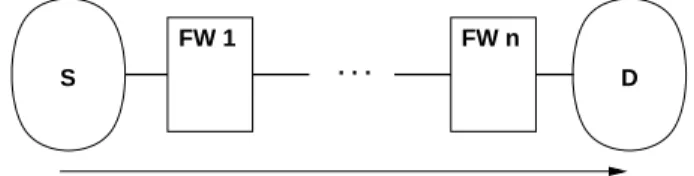
A firewall security analysis is one type of network security review. It is often done on network Layer 4, for example for TCP and UDP traffic. Figure 1 shows the basic scenario. The typical steps to be done include:
1) Normalize firewall configurations 2) Identify critical network paths
3) Identify firewalls along each critical path 4) Determine network reachability on critical paths 5) Compare reachability and security requirements 6) Identify non-compliant firewall rules
The primary motivation for creating the CNA lies in steps 4, 5 and 6. In step 4, the CNA calculates the reachability in a unified simple format that has firewall rules attached as trace information. If a formalized or easy to formalize security policy is available, it can be compared automatically to the actual network reachability. As such a security policy is often not available in practice, step 5 may still need to be done manually.
Figure 2 shows the typical application scenario. The Rule-Set Converter is not part of the core CNA system
and has to be adapted for each different firewall descrip-tion format. The CNA uses a normalized symbolic Layer 4 format internally that is based on intervals. As core contribution of this paper, we show this representation is suitable for calculating reachability even in the presence of large firewall configurations. To this end, we present benchmark calculations on deployed rule-sets. The CNA has been used successfully in firewall security reviews.
S . . . D
FW 1 FW n
Fig. 1. Unidirectional reachability along a critical network path.
The paper is organized as follows: Section II introduces our network and firewall model, and the symbolic repre-sentation used. Section III gives the operations used for single firewalls. Section IV explains how to calculate uni-directional reachability. A complexity analysis is sketched briefly in Section V. Section VI describes the implemen-tation, while Section VII states benchmark results and the effects of different optimization techniques. Section VIII explains how to extend the approach to two-sided reachability and to automated comparison with a policy. The paper finishes with a discussion of related work in Section IX and a conclusion in Section X.
raw Converter Calculation Reachability rule sets Policy Comperator Reachability Policy violations rule sets Network FW formalized Policy normalized Rule−Set
Fig. 2. Typical analysis data-flow with the CNA.
II. Approach
The reachability calculation process starts with a repre-sentation of the initial reachability (disregarding firewalls), which will often be unconstrained. This initial reachability is then successively reduced by applying firewall configu-rations. The end-result is a flat, unified representation of the firewall-chain, restricted by the initial reachability.
A. Network Model
We are primarily interested in network reachability as restricted by firewalls. Given a source networkS, sequence of firewalls FW1, . . . , FWn and a destination network
D (see also Figure 1), we say that D is reachable from S if there are network packets that can traverse FW1,
. . ., FWn without being dropped by any FWi. Note that
some attacks will needtwo-sided reachability. For example services used over TCP can usually only be attacked if response packets can traverse the firewall sequence in reverse order. See Section VIII-A for a discussion on how to check two-sided reachability.
We restrict the packet information visible for firewalls to IP addresses and ports, which results in a Layer 4 model. Each protocol is treated separately, although it is possible to mix protocols, for example by doing a forward analysis with TCP and a backward analysis with ICMP in order to determine whether an ICMP response to a TCP packet would get through. Routing is out of scope for this work, as we do not see it as a security mechanism; see Section IV-A for a brief discussion.
B. Subspaces, Boxes and Intervals
Reachability is represented by subspaces of M = src IP×src port×dst IP×dst port
We organize these subspaces into sets (lists) of axis-aligned hyperrectangles inM, also calledaxis aligned boxes[1] (or simplyboxfor short), with
A ⊆ M is represented as
A = {b1, . . . , bn} withbi∈M and bi is a box.
In this paper, boxes will always be axis-aligned. A box can be represented as a 4-tuple of intervals, which allows symbolic computations. This representation is similar to the one used in [2].
Box example:
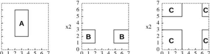
b= (10.0.0.0−10.0.0.255,1024−65535,10.1.1.1,80) We use intervals with wrap-around, where IP and port number spaces are regarded as circles. This facilitates rep-resenting complements. Figure 3 gives graphical examples of three boxes in two dimensions represented this way.
4 0 1 2 3 5 6 1 2 3 4 5 6 7 0 x2 x1 4 0 1 2 3 5 6 1 2 3 4 5 6 7 0 x2 x1 A 4 0 1 2 3 5 6 1 2 3 4 5 6 7 0 x2 x1 7 7 7 B B C C C C
Fig. 3. Example: BoxesA,BandCin two dimensions.
C. Firewall Model
The CNA uses a simple firewall model, where each firewall consists of a linear sequence of rules r that each have a box describing their applicability and one of the target actions accept or drop, with a default drop at the end of sequence. This corresponds to the ”simple” model of [3].
D. Rule Application and Set Operations
In order to apply a firewall rule r = (b, <action>) to a subspace A = {b1, . . . , bn} ⊆ M, we intersect b with
the differentbi in turn and apply the action to the result
A∩ {b}={b∩b1, . . . , b∩bn}.
The usual set operations are defined on boxes and, by extension, on subspaces of M. Some deserve additional comments. 4 0 1 2 3 5 6 1 2 3 4 5 6 7 0 x2 x1 4 0 1 3 5 6 1 2 3 4 5 6 7 0 x2 x1 2 7 7 4 0 1 2 3 5 6 1 2 3 4 5 6 7 0 x2 x1 7
Fig. 4. Box intersection, as used in rule application, shown for two dimensions.
Intersection:Intersecting two boxes inddimensions can have up to 2d
result boxes. Figure 4 illustrates this in two dimensions. For b1, b2 ∈ M, the intersection b1∩b2 may
consist of up to 16 boxes asM has 4 dimensions.
Box complement: The complement of an interval is derived by adjusting the boundaries. The complement of a box is derived by complementing each interval in turn and setting all other intervals to full range. Hence, a 4-dimensional box has four boxes as its complement. Subtraction:Calculatinga−b for boxesaand bis done by using the relationa−b=a∩¯b from set calculus.
III. Restricting Reachability by a Single Firewall
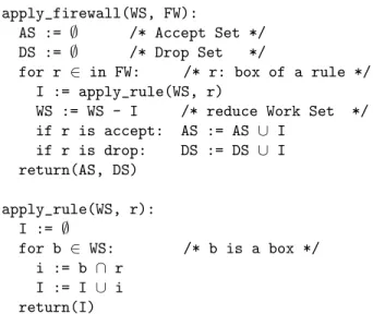
The core operations used in determining reachability through a single firewall are apply_firewall() and ap-ply_rule(), shown in Figure 5 in simplified form. The task ofapply_firewall() is to take a given reachability description, stated as a set of boxes, called here a Work Set (WS) and, using the rules of the firewall, determine both an Accept Set (AS), which is the part of the WS that can pass the firewall, and a Drop Set (DS) that is the part of the WS that cannot pass the firewall. AS and DS are represented as sets of boxes. The function apply_rule()forms the basis of apply_firewall()and implements calculation of the intersection I between the given rule and WS. The intersection I is then added to the AS for anacceptrule or to the DS for adrop rule.
Building on these two operations, more complex opera-tions can be constructed. Note thatapply_rule()may at-tach trace information to boxes, for example to document rule application. If desired, the full history of each box can be recorded in the trace. This allows to determine the specific firewall rules that are responsible for a box being in the final reachability, and represents information needed in any report about firewall configuration problems. apply_firewall(WS, FW):
AS := ∅ /* Accept Set */
DS := ∅ /* Drop Set */
for r ∈ in FW: /* r: box of a rule */
I := apply_rule(WS, r)
WS := WS - I /* reduce Work Set */
if r is accept: AS := AS ∪ I if r is drop: DS := DS ∪ I return(AS, DS) apply_rule(WS, r): I := ∅ for b ∈ WS: /* b is a box */ i := b ∩ r I := I ∪ i return(I)
Fig. 5. Pseudo-code forapply_firewall()andapply_rule() (sim-plified).
IV. Unidirectional Reachability Computation
Pseudo-code for the calculation of one-direction reacha-bility through a sequence of firewalls is given in Figure 6. We will typically choose the initial reachability as unrestricted. Starting with full, unconstrained reachability will ensure the final results only rely on the given firewall configurations. A more restricted initial reachability can still be used when appropriate. Ports are unconstrained in the initial reachability.
A. Comments on Routing
Routing can usually not be regarded as security feature in practice and is not seen as one by many customers. There are several reasons for this:
• The primary task of routing is to get packets to a specific destination, while the primary task of a fire-wall is to prevent packets reaching a specific destina-tion. Routing configuration and firewall configuration hence have diametrically opposed primary tasks and this is reflected in procedures and mind-sets.
• Due to the different primary tasks, often the teams responsible for routing and for firewalls are different. • While firewall configurations are handled securely and all updates are done with the security model in mind, routing configurations are typically changed with the network model in mind and handled in a less secure fashion. Routing is hence easier to compromise.
• Sometimes customers cannot even specify the IP ranges of S andD precisely, but have precise firewall information. This may sound surprising, but if routing delivers more to a physical target network than ex-pected, this is not necessarily a problem. For firewalls, it is a critical error.
• Routing works on Layer 3, while firewalls work on Layer 4. Mixing the two complicates things and in-creases maintenance effort.
Overall, it is far more practical to separate routing and firewalls and to require that all restrictions on reachability must be implemented by firewalls placed into the critical network paths. This is especially true for customers with complex firewall configurations.
It should be noted that with this approach, the ques-tion arises whether a specific firewall actually is on the critical network paths it is supposed to be on. Answering this question requires a network topology analysis and is outside of the scope of this work.
It should also be noted that network scanning always takes routing into account. This is a fundamental limita-tion of network scanning.
in: S, D /* Source, Destination networks */
FW1, ..., FWn /* firewalls */
out: ASn /* final reachability */
DS1,. . .,DSn /* Drop Sets */ WS1 := S × <all> × D × <all> (AS1, DS1) := apply_firewall(WS1, FW1) WS2 := AS1 (AS2, DS2) := apply_firewall(WS2, FW2) WS3 := AS2 ... (ASn, DSn) := apply_firewall(FWn−1, WSn−1)
Fig. 6. Pseudo-code for calculating unidirectional reachability with
apply_firewall()for the scenario shown in Figure 1.
V. Algorithmic Complexity
We briefly sketch the complexity analysis idea. For a worst-case scenario, start with one box and a single firewall with n drop rules. Each drop rule can split (asymptoti-cally) at most one element of the Work Set into a maxi-mum of 2d
(with dimension d= 4) non-overlapping parts that are kept in the working set. Hence, each rule increases the size of the working set by a maximum of 16, giving an overall space complexity of the result of 16∗n∈O(n). As each successive rule application has to work on 16 more boxes, time complexity is 1∗16 + 2∗16 +. . .+n∗16 = 16∗(1 + 2 +. . .+n) = 16
2n(n−1)∈O(n 2
). A very similar argument applies to accept rules and mixed rule-sets.
In comparison, in [4], the authors need worst case effort O(n4
) to build a Firewall Decision Diagram (FDD) for n firewall rules with for our firewall model. It is reasonable to
No FW / rule-set size benchmark results
FW raw nor- opt. Python input opt. trace core-loop
seq. malized baseline reduction ported to C
1 S 27 2’000 180 8min 12MB 6s 6MB 5s 6MB 0.2s 6MB
2 M 67 23’000 8300 - - 546min 84MB 222min 48MB 48s 19MB
3 L 170 27’000 3100 - - 34min 26MB 20min 18MB 4s 10MB
4 S, M 100min 32MB 294s 14MB 240s 13MB 3s 14MB
5 M, S - - 544min 81MB 336min 48MB 49s 19MB
6 M, L 5000min 187MB 660min 77MB 250min 56MB 69s 22MB
7 S, M, L 205min 58MB 370s 16MB 305s 16MB 4s 16MB
TABLE I
Benchmarks (TCP)
expect that this worst-case is extremely unlikely to happen in practice.
In [3], the authors claim a worst case complexity of O(n) for processing a firewall withnrules in their ”simple model”. However, they assume constant effort for set op-erations on their accept (A) and drop (D) sets. While the BDDs used are typically very efficient set-representations, they do not reachO(1) worst-case effort for set operations and the correctness of the given complexity analysis seems doubtful.
VI. Implementation
The CNA is implemented in Python 3 [5] with C extensions. This allows a clean and flexible OO design and facilitates targeted optimizations. IP addresses and port numbers are represented directly by Python integers. Boxes are represented as Python 8-tuples (representing 4 intervals) and encapsulated into class objects in order to allow attachment of traces, annotations and firewall rule actions. Subspaces are represented as Python lists. The pure-Python prototype is relatively slow and has high memory consumption, but can already be used for security reviews involving firewalls with small and medium-sized rule-sets.
VII. Optimizations and Benchmarks
First, note that in the absence of Network Address Translation (NAT), which is rarely deployed in security critical networks, firewalls can be arbitrarily reordered, as exactly those packets that make it throughallof them are part of the final reachability space. In particular, a good selection of the first firewall to be processed can have sig-nificant performance benefits. Benchmarks must therefore always be seen together not only with the relevant firewall configurations, but also their processing order.
A. Benchmarks
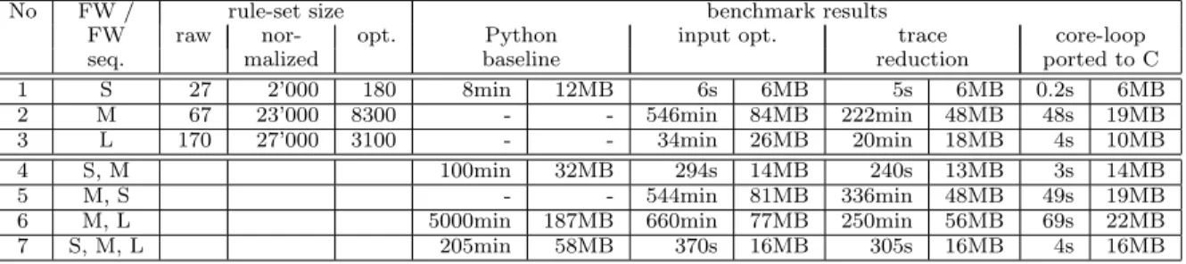
In order to determine performance and to examine the performance impact of different optimizations, we give a selection of benchmark results1
in Table I. Times are 1As with all benchmarks, it should be noted that the stated results
only give a rough idea about runtime, memory footprint and effects of different optimizations.
CPU times including input data parsing. Memory sizes are the whole process memory footprint, excluding shared areas (libraries). The calculations were done using Linux (Debian Squeeze 32bit) on an Athlon64 X2 5600+ CPU, using only one CPU at a time. Memory was set to the 4GB memory model and the machine was running kernel 2.6.38 from kernel.org without any special optimizations. Python versions used include 3.0 and 3.1 with no significant differences in performance between the two.
Lines 1,2,3 of Table I describe the firewall configura-tions used. These are firewall configuraconfigura-tions deployed in the real world. They have a flat form (no sub-chains) and a default-drop policy.
Lines 4ff. of Table I give benchmarks for different firewall combinations. The order of the firewalls is important as the first one has to be completely represented in memory, which causes effortO(|FW1|2) (where|FWk|is the number
of rules in firewall FWk). The effort for each additional
firewall in the chain isO((|WSi|+|FWi|)·|FWi|) and hence
higher in the worst case. But when starting with a firewall with small rule-set, we observed that a later combination with a firewall with a large rule-set does often not increase the WS size significantly, as most rules of the larger firewall do not apply. For that case, the complexity goes effectively down to O(|WSi| · |FWi|), which is a lot smaller than
O(|FWi| 2
) if |FWi| is is large but |WSi| is small. If the
firewall processed first has a much larger rule-set than the others, we have observed that it will often dominate the runtime.
The columns ”rule-set size” give the number of rules in the raw input in vendor format, the normalized number of rules without optimization and the optimized rule-set size. Benchmarks are given only for TCP for brevity, UDP and ICMP analysis have comparable results. We do not have benchmarks for comparison against a policy, as we do not have a sufficiently formalized policy and hence looking directly at reachability was more efficient. Comparison with a policy would incur effort comparable to adding one more firewall configuration in the size of the negated policy specification. The idea is that nothing must be able to pass though the given firewall chain andan additional firewall representing the negated policy, with the negated policy
representing all forbidden traffic.
As can be seen in Table I, each evaluated optimization step has significant impact on observed run-time. The final implementation with all optimizations included has very reasonable performance even in the presence of firewalls with large rule-sets.
B. Firewall Evaluation Sequence Optimization
The benchmarks demonstrate that the selection of the first firewall to be processed has a huge impact on per-formance. For the first firewall, the Work Set grows for each rule application, while for later firewalls only rules that have a non-empty intersection with the Work Set can increase Work Set size. Our experiences show that the most restrictive firewall configuration should be processed first. In many scenarios, this will be the smallest firewall configuration, measured in number of rules.
C. Rule-Set Representation Optimization
Firewall configuration in vendor-formats often allow more complex specifications, such as lists of multiple sources, destinations or services. Decomposing such input rules into rules using a single box each can results in a number of normalized rules that is a lot higher than needed. The reason is that many resulting rules will be overlapping or adjacent in such a way that they can be combined. The column ”opt.” under ”rule-set size” in Table I states the reduced number of rules after optimization and the column ”input opt.” gives the improved run times and memory footprints. The runtime for the input optimiza-tion itself is small, as it only works with a focus of one raw input rule at a time.
Note that global box combination would be possible, but combining boxes from different raw rules has two problems: First, if bothaccept anddroprules are present, the combination algorithm has to take rule sequence into account. And second, in this approach a box cannot be labeled with the single raw firewall rule it originated from. This makes the identification of policy-violating rules in the end-result difficult.
D. Trace Reduction
While the original prototype retained traces for all operations that changed a box, it turns out these full traces are only beneficial for debugging. In a security analysis, only accept and drop actions are relevant and hence it is enough to add trace information to a box when it is added to an Accept Set or Drop Set. It is not necessary to trace when boxes are reduced or split in the WS. Hence, traces were reduced accordingly. This also means that there can be at most one trace entry per firewall in each box contained in the result. The column ”trace reduction” in Table I states the additional performance gains. Note that trace reduction was benchmarked with input optimization applied as well.
E. Core-Loop Ported to C
In a last step, the core loop function apply_rule() was ported to C and embedded into the Python code. Contrary to Figure 5, WS, AS and DS are passed to apply_rule()and are manipulated in-place according to the rule action. This puts expensive operations, such as data-structure manipulations, into the C code. No other special optimizations were done for the C code and in particular the standard GNU libc memory allocator was used. The column ”core-loop ported to C” in Table I states final performance figures. Note that trace reduction and rule-set representation optimization was applied as well.
In addition, we performed a benchmark calculation for deployed firewall configuration ”XL”. It has a normalized rule-set size of 2.8 million rules, which reduces to 300’000 rules after input optimization. Raw rule number is 95. Representing configuration XL in memory took 20h of CPU time and resulted in a memory footprint of 900MB. This shows that firewall configurations of this size can still be processed with the CNA with reasonable effort.
VIII. Advanced Analysis
A. Computing Two-Sided Reachability
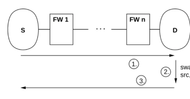
S . . . D FW 1 FW n 1. 2. 3. swap src, dst
Fig. 7. Calculating bidirectional reachability.
Two-sided Reachability allows determining whether an agent in the source network S can use a service offered in the destination network D that needs a connection, for example any service offered over TCP. It also allows limited comparison with scan results (for example from nmap [6]), which are sometimes used to verify a firewall deployment. Figure 7 gives the idea on how to obtain a two-sided reachability result.
B. Verifying Policy Compliance
Policies can be represented as an undesired reachability U, with the meaning that if anything inU ⊆M is actually reachable through the firewalls, then the policy is violated. How policies are obtained and converted into this format is outside of the scope of this work.
To test policy compliance, the actual network reacha-bilityAon each critical network path is calculated. LetV be the policy-violating reachability. ThenV =A∩U. IfV is non-empty, all elements of V represent violations. The non-compliant firewall rules can be identified by looking at the trace information attached to elements ofV, which
they inherit from A. Other compliance tests are possible and can be implemented when needed.
IX. Related Work
Reachability Analysis: One alternative to using the CNA is network scanning, for example with nmap [6]. It should be noted however that this suffers from the limitations that routing affects scanning and that normal scanning cannot find undesired unidirectional reachability. Algorithmic Firewall Analysis: It is possible to for-malize firewall functionality with a suitable logic and then use approaches from automated theorem proving to derive properties and check against violation of conditions. Work in this area includes FIREMAN [3] by Yuan, Mai, Su, Chen, Chuah and Mohapatra, which uses a BDD (Binary Decision Diagram) representation. The idea of using BDDs is developed further by Liu and Gouda [4], [7], with the introduction of Firewall Decision Diagrams (FDDs).
The query-engine of Mayer, Wool and Ziskind [8] uses a different approach. It answers questions on whether a specific packet would traverse a set of firewalls by using a rule-based simulator. This is mostly useful to determine the impact of specific firewall configuration changes. Its value in a complete firewall security analysis is limited. The Margrave Tool [9] uses a similar approach.
Commercial Tools:A commercial firewall analyzer is offered by AlgoSec [10]. This tool seems to be targeted at maintenance and administration of large numbers (up to 1000) of firewalls. Commercial firewall maintenance tools with limited audit capabilities are also offered by Tufin [11] and FireMon [12].
X. Conclusion and Future Work
We have designed and implemented the CNA (Con-secom Network Analyzer), a tool that calculates network reachability through a series of firewalls given as a Layer 4 abstraction by symbolic simulation. The primary use is for real-world security audits that examine firewalls with large rule-sets. While using set operations to model firewalls is simple, to the best of our knowledge we are the first to demonstrate that an abstraction based on intervals for reachability and firewall rules is efficient enough to calculate reachability through large deployed firewall con-figurations in practically useful time and with moderate memory footprint, while at the same time retaining the capability to annotate each result sub-set with a full trace
of the applied firewall rules. Automated result annotation is essential when analyzing firewall chains that include firewalls with a large number of rules.
One possible direction for future work is optimizing the CNA. First, the representation of the Work Set can be improved. Using ideas from geometric search, the Work Set could be organized into a data-structure that efficiently al-lows searching for all boxes that intersect a given box. This could speed up rule application significantly. A second possible optimization direction is optimization of memory management. Run-times and memory footprint could be improved by reducing traces to a fixed size format and by providing a custom allocator to the core-loop. Finally, the CNA could be adapted to handleIPv6in the future. This may need specific performance optimizations. We plan to defer IPv6 adaption until there is market demand. Acknowledgement:We thank the Swiss KTI and Con-secom AG for funding parts of this work and the anony-mous reviewers for helpful suggestions on how to improve the paper.
References
[1] “Wikipedia: Hyperrectangle,” http://en.wikipedia.org/wiki/ Hyperrectangle, last visited January 2012.
[2] P. Eronen and J. Zitting, “An expert system for analyzing firewall rules,” inProc. 6th Nordic Worksh. Secure IT Systems, 2001, pp. 100–107.
[3] L. Yuan, J. Mai, Z. Su, H. Chen, C.-N. Chuah, and P. Mo-hapatra, “FIREMAN: A Toolkit for FIREwall Modeling and ANalysis,” inIEEE Symposium on Security and Privacy, 2006, pp. 199–213.
[4] A. X. Liu and M. G. Gouda, “Diverse firewall design,” in
IEEE Transactions on Parallel and Distributed Systems, 19(8), August 2008.
[5] “Python Homepage,” http://python.org/, last visited January 2012.
[6] “Nmap Security Scanner,” http://nmap.org/, last visited Jan-uary 2012.
[7] A. X. Liu and M. G. Gouda, “Firewall policy queries,” inIEEE Transactions on Parallel and Distributed Systems, 20(6), June 2009.
[8] A. J. Mayer, A. Wool, and E. Ziskind, “Offline firewall analysis,”
Int. J. Inf. Sec., vol. 5, no. 3, pp. 125–144, 2006.
[9] T. Nelson, C. Barratt, D. J. Dougherty, K. Fisher, and S. Kr-ishnamurthi, “The Margrave Tool for Firewall Analysis,” in
USENIX Large Installation System Administration Conference (LISA), 2010.
[10] “Algosec Homepage,” http://www.algosec.com/, last visited January 2012.
[11] “tufin Homepage,” http://www.tufin.com/, last visited January 2012.
[12] “FireMon Homepage,” http://www.firemon.org/, last visited January 2012.