ARIES-RS maintenance approach for high availability
S. Malang
a,*, F. Najmabadi
b, L.M. Waganer
c, M.S. Tillack
baForschungszentrum Karlsruhe GmbH,Postfach3640,D-76021Karlsruhe,Germany bFusion Energy Research Program,Uni6ersity of California San Diego,
9500Gilman Dri6e,La Jolla,CA92093-0417,USA cMcDonnell Douglas Corporation,P.O.Box
516,St.Louis,MO63166-0516,USA
Abstract
The ARIES-RS tokamak power plant study developed a design approach which has the potential for high availability. One of the keys for high plant availability is a design that allows rapid replacement of the power core sectors. This is achieved by using large maintenance ports for each power core sector, enabling the removal of entire sectors composed of inboard and outboard blankets, neutron shields, and upper and lower divertors. Another important feature is the location of all connections to the cooling system inside the port area and outside the plasma chamber, avoiding contamination of the chamber by coolant leaks or handling operations. Any spread of radioactive particles (e.g. tritium or dust) is avoided by the use of flasks for the transfer of used sectors to the hot cells and return of new or refurbished sectors. It is estimated that the impact on availability is less than 5% for scheduled maintenance of the power core. © 1998 Elsevier Science S.A. All rights reserved.
1. Introduction
The ARIES team has selected a steady-state, reversed shear tokamak, described by Najmabadi [1] and Kessel [2], as a reference design because it promises the best combination of good economic performance and physics credibility as reported by Mau [3]. The ARIES-RS design is based on a commercial fusion power plant with a net electric-ity production of 1000 MW. The power core has a double null divertor configuration and
self-cooled lithium/vanadium blankets, segmented
toroidally into 16 sectors. A major emphasis has been placed on design features leading to high overall availability of the plant.
The availability of a power station has a large impact on the cost of electricity and, thus, on the attractiveness of the entire plant since utilities cannot accept frequent shutdowns or extended replacement periods due to the high cost of re-placement power. The availability is set by the reliability of the components (mean time to fail-ure, which sets the frequency of unscheduled maintenance), their lifetime (which sets the fre-quency of scheduled maintenance), and the time required for replacement. In particular, it is pru-dent to ensure that the maintenance scheme for scheduled maintenance can be used as much as possible for unscheduled maintenance.
Self-cooled lithium blankets with a vanadium alloy (V-4Cr-4Ti) as the structural material were selected for ARIES-RS as described by Tillack [4], in part because they provide a good basis for high * Corresponding author.
0920-3796/98/$19.00 © 1998 Elsevier Science S.A. All rights reserved.
reliability. This blanket concept enables a simple design with a small number of cooling channels and low mechanical stresses in the blanket struc-ture. This structural material shows promise for an exceptionally long lifetime since the allowable neutron fluence is probably limited by irradiation creep only and not by swelling or helium embrit-tlement, as detailed by Billone [5].
In addition, the ARIES-RS plant is configured for quick replacement of the power core compo-nents. The overall goal was a core and mainte-nance design that could achieve an overall plant availability of 90%. Allocations of availability goals for the power core, reactor plant equipment, and the balance of plant were established at 95%, 97.5%, and 97.5%, respectively, for both planned and unplanned maintenance. This ambitious power core goal can only be accomplished with replacement of many or all sectors in a very short period, with many parallel maintenance opera-tions. This scheme also minimizes the need for in-situ repair of the components. The failed com-ponents are replaced and the power plant is brought on line while the failed unit is removed to a hot cell for repairs. Such a quick replacement is not possible with a vertical replacement scheme, as reported by Sherwood [6 – 8]. Several earlier fusion reactor conceptual design studies employed horizontal maintenance for power core compo-nents. The Starfire conceptual design [9] removed individual blanket segments through 12 individual access doors. INTOR [10,11] and FED [12] also removed sectors between individual TF coils with a smaller maintenance port for the more fre-quently replaced divertor module. The JAERI DREAM [13] reactor is a contemporary reactor design that emphasizes maintenance with large sectors withdrawn between TF coils and plumbing access through the central solenoid column. Based upon these works and recent evaluations within the project, ARIES-RS has been designed for horizontal insertion and withdrawal of entire sec-tors along rails.
The major design features discussed here are power core and vacuum vessel configuration, de-sign of the removable power core sectors, connec-tion and assembly of the removable power core sectors, alignment and attachment of the power
core sectors, connections of coolant access tubes to power core sectors, and transfer of power core sectors to hot cells.
2. Power core configuration
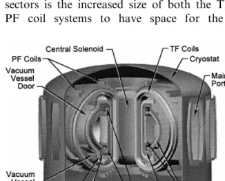
The overall layout of the ARIES-RS fusion power core is shown in Fig. 1. Each sector has its own horizontal maintenance port, allowing re-placement of the entire sector without opening the cryostat or disassembling other components such as the coil system.
Each maintenance port is sealed by two doors which enclose a separate vacuum distinct from the plasma and cryostat vacuum enclosures. The in-ner door serves as the outboard low temperature shield, while the outer door is located at the radius of the cryostat. All coolant access tube connections are made in the antechamber inside the port, avoiding any contamination of the plasma chamber by coolant leaks or particulate from the maintenance procedure. A separate vac-uum inside each port enables the use of mechani-cal seals for coolant connections as well as for the two doors, thus decreasing the time required for maintenance.
One of the most severe penalties of single-piece sectors is the increased size of both the TF and PF coil systems to have space for the large
maintenance ports between the outer legs of the TF coils. The increase in capital cost, which is estimated to be about 5%, has to be compared with the benefit of the increased availability due to the faster maintenance. This general horizontal maintenance scheme was proposed in the
ARIES-II/IV designs as reported by Najmabadi [14] and
Sharafat [15], but additional work has been done in ARIES-RS to improve the engineering feasibil-ity and desirabilfeasibil-ity.
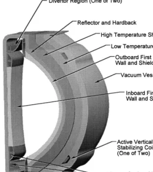
3. Design of the removable power core sectors One of the distinctive aspects of the ARIES-RS fusion power core is the integral construction of the sectors. All blanket, reflector and shielding segments of a sector are integrated with the diver-tor components into one replacement unit to min-imize time-consuming handling inside the plasma chamber. This replacement unit is attached to the bottom structure of the vacuum vessel and can be connected and disconnected by working from the port area. A hardback structure integrates all the inboard, outboard, and divertor elements into a single, removable sector module.
The elements of a 22.5° sector of the power core, which are integrated into one removable unit as shown in Fig. 2, are: (a) Inboard Region [First Wall/Blanket, Reflector/Hardback]; (b) Di-vertor Region [Upper and Lower DiDi-vertor
Struc-ture/Hardback, Divertor Plates]; and (c)
Outboard Region [First Wall/Front Zone of
Blan-ket, Reflector/Rear Zone of Blanket/Hardback,
High Temperature Shield, Low Temperature Shield].
Fig. 3 shows a plan view through the power core at the midplane with the sector being par-tially withdrawn, illustrating the main elements of a removable sector.
To maximize the useful lifetime of all elements as well as minimize the waste stream, all power core elements are subdivided into radial zones characterized by different lifetimes. No welds are used between elements of different lifetime classes, thus allowing easy disassembly in a hot cell and reuse of elements not at the end of their lifetime.
Fig. 2. Isometric of removable sector.
There are three lifetime classes: 2.5 FPY (Full Power Years), 7.5 FPY, and 45 FPY. The short-est-lifetime class is the plasma facing components: the first wall plus the inner part of the blanket and the divertor plates. Underneath those compo-nents are the elements with intermediate lifetime: the inboard reflector, the divertor structure, and the outboard reflector plus outer part of the blan-ket. These latter elements constitute an integral hardback support structure, or ‘skeleton ring’, capable of withstanding large loads caused by gravity and disruption forces. Attached to this structure at the inner side are the plasma facing
Fig. 3. Plan view through power core at midplane, removable sector being withdrawn.
components, and at the outer side of the outboard region are the high and low temperature shields which are lifetime components. The two shielding zones at the outboard region are also part of the replacement unit in order to facilitate replacement of the power core sector. All zones not at the end of their lifetime during scheduled maintenance will be separated in the hot cell and reused. High-and low-temperature shields at the inboard region as well as at the divertor region are also life-of-plant components and can remain at their normal position during the removal of a replacement unit. Another advantage of graded regions is the thermal-hydraulic decoupling of the zones. In both the blanket and divertor, the rear zone (far-thest from the plasma) is used as a superheater to maximize the coolant bulk outlet temperature. The coolant always enters in the regions of highest surface heat flux, where surface tempera-tures are difficult to maintain within their design limits, and exits in regions heated exclusively by volumetric heating. This configuration works es-pecially well with self-cooled blankets which ab-sorb volumetric heating directly in the coolant.
4. Connection and assembly of the removable power core sectors
The connections between the structural ring and the attached elements must be designed to maintain a constant distance in the radial direc-tion, but differential thermal expansion in the poloidal and toroidal direction is accommodated without large thermal stresses. These connections have to be designed to transfer disruption and gravity forces. In order to achieve the mainte-nance goals, these connections must also be con-nected and disconcon-nected in the hot cell, probably without welding. The assumption has been made that the total force acting in the horizontal direc-tion is in the order of 200 tons, which is 10 times larger than the gravity force acting on the first zone (first wall plus part of blanket). This as-sumption leads to a design of the links with a strength comparable to the stiffness of the outer walls of the segments, which are 10-mm thick. If future disruption calculations indicate larger
forces, both the outer walls of the segments as well as the connecting links will have to be strengthened.
The divertor plates are made of 5-cm thick vanadium plates with small cooling channels at the plasma facing side. The requirements to attach these plates to the support structure are: (1) plates must be precisely aligned, (2) must allow differen-tial expansion without large thermal stress, (3)
attachment must withstand large disruptive
forces, and (4) plates must be replaceable from
within the hot cell without cutting/rewelding
highly irradiated parts. These requirements can be met with threaded, hollow bolts which are flexible enough to allow for differential thermal expansion between the plates and support structure without excessive, large bending stresses. The bolts can radiate the volumetric heat to the surroundings at a temperature below the 700°C temperature limit for the vanadium alloy. The number and the location of the bolts will be determined by disrup-tion forces. The distance between the plates and support structure can be adjusted by turning the threaded bolts.
The different elements of the power core sector have to be connected in a manner which allows them to be separated in the hot cell without cutting or welding. This will allow some of the elements to be reused with minimum difficulty. Therefore no field-welded coolant connections can be inside the radiation environment. For this rea-son, each element has separate coolant access tubes which are connected inside the maintenance port. Lead-throughs (Fig. 4) are required for these coolant tubes which penetrate the vacuum vessel. The coolant tubes must be flexible to allow for differential thermal expansion.
5. Alignment and attachment of the power core sectors
Each removable sector (Fig. 2) weighs approxi-mately 170 metric tonnes. These sectors must be aligned inside the plasma chamber within a few millimeters for proper function. Since the gravity forces can be reacted directly at the base of the module, the removable sectors will be attached to
Fig. 4. Principle of the lead-throughs of the coolant access pipes through the vacuum vessel.
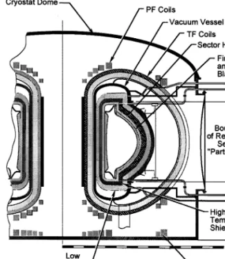
Fig. 6. Vertical cross-section of torus and a maintenance port. the bottom structure of the vacuum vessel. Each
module will expand equally in the vertical and
radial direction when heated to operating
condition.
Since rolling or sliding support elements would not survive the operating environment inside the plasma chamber, they will have to be removable. The proposed solution is to insert a hydraulic system for vertical and horizontal alignment of the sector during installation. Low friction sur-faces will be provided for ease of movement and to avoid seizing. A clearance gap in the rails allows for precise alignment. This gap will be filled with a suitable alloy that can be melted for alignment but which will solidify when cooled down to the operating condition of the power core structure. After solidification, the sector will be firmly supported in all directions. Fig. 5
illus-trates a rail system for sector removal and support.
6. Connections of coolant access tubes to power core sectors
The entire power core is cooled by liquid lithium with an inlet temperature of 330°C and an exit temperature of 610°C. For the replacement of a sector, 6 – 8 coolant access tubes have to be disconnected and reconnected to the new sector. All these connections are located outside the plasma chamber in an antechamber enclosed by the maintenance port and the outer and inner maintenance door. This is illustrated by Fig. 6, which shows a vertical cross-section of the torus.
7. Transfer of power core sectors to hot cells The maintenance approach is to transfer entire power core sectors to a hot cell when one of the elements fails (unscheduled) or is at the end of its lifetime (scheduled) rather than remove a single Fig. 5. Support and alignment rail concept.
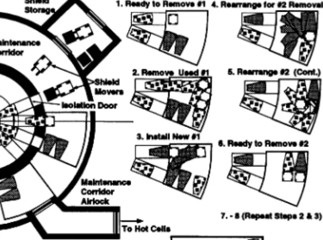
Fig. 7. General arrangement of sector maintenance with the multiple transporter concept.
There is an important choice to be made in regard to the size of the transfer flask. The smallest size accommodates a single sector but requires two docking operations to the port for the removal of the used sector and the installation of a new one. One docking operation can be accomplished if the flask is enlarged to simulta-neously handle both a used and a new sector. The removal of two neighboring sectors with one docking operation is possible if the flask is further enlarged to accommodate two new sectors and old sectors. An example of this multiple-port flask is shown in Fig. 7 along with the steps to ex-change sectors within the flask. The optimum choice between the individual and multiple flask concepts depends on the time required for dock-ing as well as on the number of sectors to be replaced during a reactor shut-down.
The overall goal is to maximize the availability of the power station. This requires a suitable strategy for the scheduled replacement of the power core sectors. An attempt should be made to combine sector replacement with other general maintenance operations into one shut-down pe-riod, even if this would result in a yearly replace-ment of part of the power core.
Unfortunately, it is not possible at this stage to obtain validated estimates for the required shut-down time to replace power core sectors. Esti-mates range from 4 to 16 days if parallel handling of all sectors to be replaced is assumed. The time estimate for the repetitive tasks if sectors are replaced in series ranges from 1.5 to 12 days.
These estimates are not precise enough to select the transporter concept (single or multiple sector flasks) or to decide on the number of sectors to be replaced during a shut-down period. However, they already give some confidence that a reason-able availability can be achieved with the selected maintenance approach.
8. Conclusions
The ARIES-RS tokamak design provides a sep-arate maintenance port for each power core sec-tor. This enables efficient replacement of entire sectors, which is a key feature for rapid mainte-internal element from inside the torus. This
trans-fer will require protection from the radioactive particles such as tritium or activated dust and perhaps from high-level gammas, depending on the design of the building’s shield. Any connec-tion between the plasma chamber or the sectors to be removed and the building atmosphere has to be avoided to prevent the spread of radioactive materials. After operation, hands-on maintenance is not possible; hence, all handling of the power core must be performed with remote control.
The proposed solution is to employ large trans-fer flasks for the transport of power core sectors to the hot cell. After a bioshield door is removed and temporarily stored, the flasks are attached to the outer flange of a maintenance port prior to opening the doors of the port. In this way, the radioactive materials from the plasma chamber (e.g. tritium or dust) are contained. After attach-ment, both doors will be opened and the equip-ment, including the rail system for the removal of the sector, will be moved from the flask into the maintenance port. All coolant access tubes can be disconnected prior to opening the inner door of the port. The rail system is installed to support the power core sector, which is then detached from the bottom structure by melting the metal in the gaps of the rails. The used power core sector can then be moved into the flask.
nance. The selected maintenance approach is to attach the sector to the bottom structure inside the vacuum vessel with the help of a solidifying liquid metal. All connections to the cooling sys-tem are located in an antechamber inside the port, which has a separate vacuum enclosed by two maintenance doors. This avoids any handling op-eration inside the plasma chamber, which would be very time consuming and could lead to con-tamination of the chamber. Any spread of ra-dioactive material to the reactor hall is avoided by the use of a flask for transferring used power core sectors to the hot cells. As a result of all these measures, it has been estimated that the impact on availability can be kept below 5% for scheduled power core maintenance. This maintenance ap-proach will increase the total capital cost about 5% as compared to a design with TF-coils closely fitting the outboard blankets.
References
[1] F. Najmabadi, et al., The ARIES-RS power plant, Fusion Eng. Des. 41 (1998) 365 – 370.
[2] C.E. Kessel, J. Manickham, G. Rewoldt, W.M. Tang, Improved plasma performance in tokamaks with negative magnetic shear, Phys. Rev. Lett. 72 (8) (1994) 1212. [3] T.K. Mau, D.A. Ehst, S.C. Jardin, C.E. Kessel, B.J. Lee,
and the ARIES Team, Plasma system requirements and performance database for the Starlite/Demo fusion power
plant, 16th EKE Symp. Fusion Eng., September 30 – Oc-tober 5, 1995, Champaign, IL.
[4] M.S. Tillack, Engineering design of the ARIES-RS power plant Fusion Eng. Des. 41 (1998) 491 – 499.
[5] M.C. Billone, Database and design criteria for V-4Cr-4Ti as a fusion reactor structural material, ISFNT-4, Univer-sity of Tokyo, Tokyo, Japan, April 6 – 11, 1997. [6] D.V. Sherwood, J. Pearcey, Maintenance of a fusion
reactor for high availability and its implications for safety, NNC rep. FR/E/004399A, June 1993.
[7] D.V. Sherwood, R.W. Seddon, R. Hancox, J.-C. Sublet, Evaluation of maintenance concepts suitable for fusion power reactors, Fusion Eng. Des. 22 (1993) 367 – 378. [8] D.V. Sherwood, J. Pearcey, H.M. Thompson, J.-C.
Sub-let, N.P. Taylor, Maintenance of a commercial fusion power station and its implications for safety, Fusion Eng. Des. 31 (1996) 29 – 39.
[9] C.C. Baker, et al., Starfire: A Commercial Tokamak Fusion Power Plant Study, Argonne National Laboratory Report ANL/FPP-80-1, 1980.
[10] W.M. Stacey, Jr., et al., The US contribution to the international tokamak reactor workshop. Phase I, USA INTOR/80-1, June 1980.
[11] W.M. Stacey, Jr., et al., US FED-INTOR activity and US contribution to the international tokamak reactor work-shop. Phase IIa, USA FED-INTOR/82-1, October 1982. [12] P.H. Sager, et al., FED baseline engineering studies
re-port, ORNL/FEDC-82-2, April 1983.
[13] S. Nishio, et al., Improved tokamak concept focussing on easy maintenance, Fusion Eng. Des. 41 (1998) 357 – 364. [14] The ARIES Team, F. Najmabadi, R.W. Conn, The ARIES II and ARIES IV second stability reactors, Fu-sion Technol. 21 (1992) 1721 – 1728.
[15] S. Sharafat, et al., Design and layout and maintenance of the ARIES IV tokamak fusion plant, 15th IEEE/NPSS Symp. Fusion Eng., October 11 – 15, 1993.
.