LinkWare
TMCable Test Management Software
Getting Started Guide
October 2002, Rev. 6 5/06
© 2002-2006 Fluke Corporation. All rights reserved.
Table of Contents
Title Page
Introduction ... 1
Contacting Fluke Networks ... 2
Mimimum PC Recommendations... 3
Localizing the LinkWare Window... 3
Using the Online Help ... 3
Connecting the Tester to a PC... 3
Connecting the Memory Card Reader to a PC... 4
Importing Test Records... 4
Using the Import Wizard... 5
Opening CableManager Files ... 7
Working with a LinkWare Database ... 8
Looking at Test Results... 9
Organizing Your Database ... 10
Adding and Editing Database Information... 16
Customizing Your Report’s Appearance... 19
Printing Your Reports ... 19
Previewing Reports and Summaries... 19
Printing Reports and Summaries ... 19
Making PDF Files for Delivering Reports Electronically ... 23
Saving Your Database... 24
Creating Cable ID Lists ... 25
Creating Cable ID Lists for a DTX Tester ... 25
Creating Cable ID Lists for a DSP-4300... 26
Creating Circuit ID Lists for an OMNIScanner Tester ... 28
Creating Fiber ID Lists for an OptiFiber Tester... 29
Getting Started with LinkWare
Cable Test Management Software
Introduction
LinkWare Cable Test Management Software is a Windows program that
helps you organize, customize, print, and save copper and fiber cable test records from the following Fluke Networks testers:
• DTX Series CableAnalyzer • DSP Series CableAnalyzer • OMNIScanner • PentaScanner • OF-500 OptiFiber Certifying OTDR • CertiFiber • SimpliFiber • FM150 Fiber Meter
LinkWare includes support for the ANSI/TIA/EIA-606-A Administration Standard for Commercial Telecommunications Infrastructure. You can add 606-A
administration information to your LinkWare database and print administration records in addition to cable test reports.
This guide helps you get started importing test records and creating test reports with LinkWare software. For additional information, see the LinkWare online help.
Contacting Fluke Networks
Notes
If you contact Fluke Networks about your tester, have the tester's software and hardware version numbers available if possible.
If you contact Fluke Networks about this software, have the software’s version number available, along with the type and version number of the operating system on the PC. This
information is available by clicking Help > About… on the
software’s menu. www.flukenetworks.com [email protected] +1-425-446-4519 • Australia: 61 (2) 8850-3333 or 61 (3) 9329-0244 • Beijing: 86 (10) 6512-3435 • Brazil: 11 3044 1277 • Canada: 1-800-363-5853 • Europe: +44-(0)1923 281 300 • Hong Kong: 852 2721-3228 • Japan: 03-3434-0510 • Korea: 82 2 539-6311 • Singapore: 65-6799-5566 • Taiwan: (886) 2-227-83199 • USA: 1-800-283-5853
Visit our website for a complete list of phone numbers.
To reach us by mail
Fluke Networks PO Box 777
Everett, WA 98206-0777 USA
Mimimum PC Recommendations
Mimimum PC Recommendations
• 200 MHz Pentiummicroprocessor system
• 64 MB of RAM
• Windows 98 or later operating system.
• PC monitor with minimum 800 x 600 resolution
Note
You need administrator rights on the PC to install LinkWare software.
Localizing the LinkWare Window
To change the language for LinkWare and for printed reports
Select Options > Language.
To change the length units and the date, time, and number formats
Select Options > Display.
Using the Online Help
The LinkWare online help provides detailed information on LinkWare features.
To get help for the current LinkWare window
Press F1.
To see the online help contents or search the help for a specific topic
Select Help on the LinkWare menu; then select Contents or Search.
Connecting the Tester to a PC
Connect the tester to a serial (RS-232) or USB port (DTX, OMNIScanner, and OptiFiber testers) on the PC using the serial or USB cable that came with the tester.
Details on the serial and USB connections, including descriptions of the interface cables, are provided in the LinkWare online help.
To connect a tester to a serial port (RS-232) 1 Connect the tester to a serial port on the PC.
-continued-2 Select Options > Serial Port in the LinkWare window.
3 In the Serial Port Options dialog, set the COM number under Serial Port
to match the port number on the PC.
4 Click Test Connection.
Note
The Test Connection function does not support the FM150 Fiber Meter.
To connect a tester to a USB port
Connect the tester to a USB port on the PC while Windows is running and the tester is on.
Connecting the Memory Card Reader to a PC
Some testers can store test records on a memory card, and come with a USB memory card reader for uploading the records to a PC. Older DSP testers included a parallel memory card reader.
To connect a USB memory card reader to a USB port
Plug the reader into a USB port on the PC while Windows is running.
For details on connecting the parallel memory card reader, select “parallel memory card reader” in the LinkWare online help index.
Importing Test Records
Note
If you don’t have any test data, but want to practice using LinkWare, you can use the sample file included with LinkWare software. The sample “.flw” file is copied to your LinkWare directory during installation.
You can import records from a Fluke Networks cable tester, a memory card, or from Scanlink or Data-LINK files.
If the cable IDs for the records include characters that represent infrastructure elements, such as patch panels and telecommunications spaces, you may want to use the LinkWare Import Wizard to automatically organize your database. See “Using the Import Wizard” on page 5 for details.
Using the Import Wizard
To import test records into a LinkWare database
Import
button
1 Click the Import button.
2 Select the source for the records from the dropdown list.
If LinkWare cannot connect to the tester or reports errors during data transfer, see “Connection Problems” in the LinkWare online help for troubleshooting information.
Using the Import Wizard
When you import records, the LinkWare Import Wizard can automatically build or add to a database structure and place the records at the correct levels based on characters in the cable IDs. For example, if your cable IDs contain characters that represent patch panels, telecommunications rooms, and floors the Wizard can add these icons to the database structure; then place the records at the correct levels in the structure.
To use the Import Wizard
1 If you are importing records from a tester, connect the tester to the PC.
2 Open a new or existing LinkWare database.
3 Click the Import button; then select Import Wizard.
4 Click Next. Follow the instructions in the next two dialog boxes to select a
source for the records. Click Next after you have made your selection in
each box.
5 Select an option for organizing the test records:
• Use the tester’s organization
This option organizes the records as they are organized in the tester:
¾ DSP records are organized by the site names used in the tester.
¾ OMNIScanner and PentaScanner records are organized by the
project names used in the tester.
¾ DTX and OptiFiber records are organized by the folder names used
in the tester. Folder names are assigned to project icons in the database structure.
¾ CertiFiber records are organized by the job names used in the
tester. Job names are assigned to project icons in the database structure.
¾ SimpliFiber and FM150 records are organized by the project name
• Use the level currently selected in the database structure pane
This option places all the imported records at the currently-selected level or at a lower level if one is defined by the tester’s organization. This option is not available if a level is not currently selected.
• Define the fields used in the cable IDs
This option lets you tell the Import Wizard which cable ID characters were used to represent the elements in the cabling installation.
If you select this option, click Define cable ID fields to define the fields.
This option gives you the following choices:
Use the following delimiter to separate the cable ID fields
Choose this option if the cable ID fields are separated by dashes,
slashes, periods, or any other delimiter (for example C.A5.23). Enter the delimiter in the box. If the IDs use more than one type of delimiter, use the other option.
After you enter the delimiter, use the Field Number boxes to define
which ID field represents which element in the installation. You do not need to define fields for all the elements listed.
Click OK when you are finished.
Define location of the characters for each field in the cable ID
Choose this option if the cable ID fields are not separated by a
delimiter (for example, CA523), or if the IDs use more than one type of delimiter (for example, C/A5-23).
Use the Position of First Character and Number of Characters boxes to
define the positions and lengths of cable ID fields. You do not need to define fields for all the elements listed.
Opening CableManager Files For example, for the cable ID C/A5-23, where “C” is the room, “A5” is
the rack, and “23” is the patch, you would set the character positions as follows: Room C ABCDEFGHIJKLMNOPQRSTUVWXYZ Rack A5 ABCDEFGHIJKLMNOPQRSTUVWXYZ Patch 23 ABCDEFGHIJKLMNOPQRSTUVWXYZ
Click OK when you are finished.
6 Click Next, then click Finish to import the records.
Opening CableManager Files
To open a Fluke CableManager (.fcm) file
Click the Open button, then set Files of type: to .fcm in the Open dialog box;
Working with a LinkWare Database
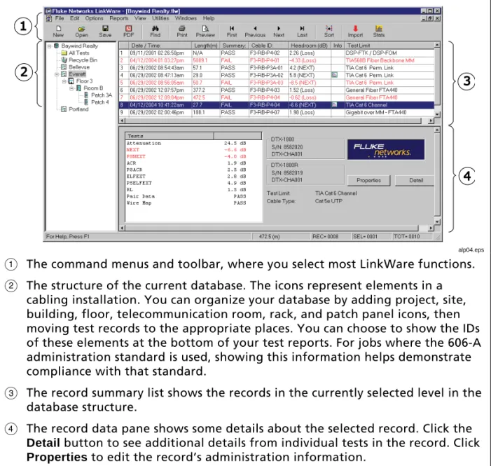
The main LinkWare window shows the structure of the database and lets you view summaries of the records in the database, as shown in Figure 1,
alp04.eps
A The command menus and toolbar, where you select most LinkWare functions.
B The structure of the current database. The icons represent elements in a
cabling installation. You can organize your database by adding project, site, building, floor, telecommunication room, rack, and patch panel icons, then moving test records to the appropriate places. You can choose to show the IDs of these elements at the bottom of your test reports. For jobs where the 606-A administration standard is used, showing this information helps demonstrate compliance with that standard.
C The record summary list shows the records in the currently selected level in the
database structure.
D The record data pane shows some details about the selected record. Click the
Detail button to see additional details from individual tests in the record. Click
Properties to edit the record’s administration information.
Working with a LinkWare Database
Looking at Test Results
Plot icon
Note icon
To see the results in a record
Click on the record in the list. If a copper test record includes
plot data, the plot icon appears in the Info column.
If a note has been entered in the record’s report properties, the
note icon appears in the Info column.
To see detailed test results for the highlighted record
Click the Detail button near the lower-right corner of the main LinkWare window,
or double-click on a record. This brings up the results pop-up window, as shown in Figure 2.
To see the additional details about the test
Click the Detail button on the Summary tab in the detail pop-up window.
To see the plot for a test
Click the test's tab in the results pop-up window; then click a Plot button.
link0014.bmp
Print Preview
button
To see what a printed report or summary will look like
Select File > Print Preview. You can quickly preview reports by clicking
the Print Preview button.
Organizing Your Database
You can organize your database by changing the database structure and by moving and sorting the records.
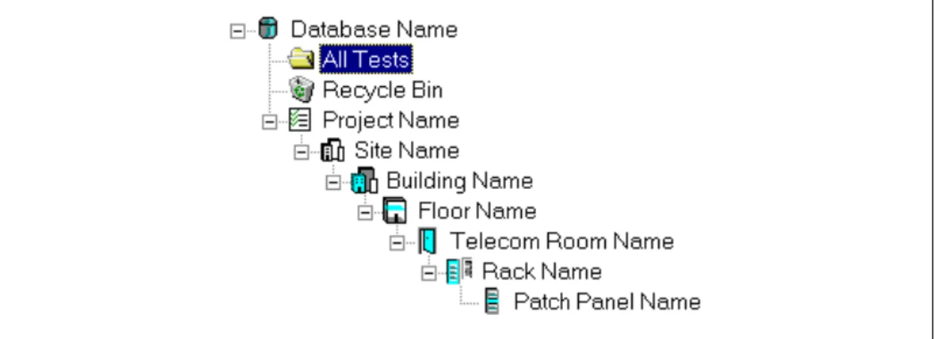
Structuring Your Database
The database structure at the left side of the main LinkWare window lets you structure your database to match the layout of the cabling installation. Figure 3 shows an example of a database structure with icons added to represent elements in the installation. Table 1 describes the icons in the LinkWare database structure.
In the Printing Options dialog, you can choose to show the IDs of the
installation elements at the bottom of printed reports. For jobs where the 606-A administration standard is used, showing this information helps demonstrate compliance with that standard.
link0033.bmp
Working with a LinkWare Database
Table 1. Database Icons
Icon Description
LinkWare database: This icon shows the name of the LinkWare database.
All Tests folder: This folder contains all the test records in the database.
Recycle Bin: The bin contains any tests you have deleted.
Project: A customer name, work order, or other project identifier. If you import records from an OMNIScanner, PentaScanner or CertiFiber tester, LinkWare creates a Project icon for each project or job name used in the tester. For SimpliFiber or FM150 records, LinkWare creates a Project icon with the project name you entered during the import process.
If you import records from a DTX or OptiFiber tester, LinkWare creates a Project icon for each folder name used in the tester.
Site: A job site.
If you import records from a DSP tester, LinkWare creates a Site icon for each site name used in the tester.
Building: A building at a job site.
Floor: A floor in a building.
Telecom room: A telecommunications room on a floor.
Rack:A rack of patch panels in a telecommunications room.
Patch panel: A patch panel, punch-down block, or group of panels or blocks with sequentially numbered ports.
To add levels to the database structure
Right-click on an existing icon that is one level up from the level you want to
add. Select Add new from the popup menu, then select an icon to represent
the level you want to add.
To edit an icon’s properties, which include 606-A information for some icons
Right-click on the icon; then select Properties.
To see all the records at the levels below a level in the database structure
Right-click anywhere in the structure; then select Include lower-level records
from the popup menu.
To rename an icon
Right-click on the icon's label. Select Rename from the popup menu; then
enter a new name in the label box. Press ENTER or click on a different icon when you are finished.
To rename the database icon
Select File > Save As to save the database with a different name.
To move an icon in the database structure
Use the mouse to drag the icon and drop it in a new location.
To delete an icon from the database structure
Right-click on an icon; then select Delete from the popup menu. Deleting an
icon also deletes all lower-level icons and all records stored at and below the deleted icon.
To restore deleted icons and their associated records
Select the records in the recycle bin, right-click on the selected records; then
Working with a LinkWare Database
Moving Records
After you import records into a LinkWare file and build a database structure, you can organize the records by moving them to the appropriate locations in the database structure. You can also move records to another database.
To move records between levels in the database structure
1 Click on the name in the database structure where the records are located.
Note
If Include lower-level records is checked, moving records out of any location also moves them from all lower locations.
2 Select the records you want to move.
3 Using the mouse, drag the records and drop them in the desired location.
To move records to another LinkWare database
1 Open the source and destination databases.
2 If the structure of the destination database does not include an icon at the
Project level or below, create one now.
3 Select Windows > Tile fromthe LinkWare menu.
4 Select the records you want to move; then drag and drop them on an icon
or record list at the Project level or below in the destination database.
Copying and Pasting Records
To copy records within the current LinkWare database or to another LinkWare database
1 Select the records in the record list.
2 Select Edit > Copy or type Ctrl +C.
3 In the database structure, click on the destination for the records.
Note
You can paste records only to icons at or below the Project
level in the database structure. If an icon does not exist at or
below the Project level, create one as the destination for the
records you will paste.
Deleting and Restoring Records
You can delete a record from any location in the database structure. Deleting a record removes the record from all levels in the database. For example, if a
record is stored in a patch panel icon, and Include lower-level records is
selected, you could delete the record from the patch panel icon or from any icon above it.
You can also delete duplicate records that were mistakenly imported twice or copied and pasted within the same database. This function finds duplicate records by comparing cable IDs and timestamps. Deleting duplicate records deletes all duplicates at the level you select and below.
Deleted records go into the LinkWare Recycle Bin, where they remain until you empty the bin, move the records, or restore the records.
To delete records
Select the records; then press Delete on the keyboard.
To delete duplicate records
Click on the database icon where you want duplicate records deleted; then
select Utilities > Delete Duplicate Records.
To delete a database icon and all the records stored in that icon
Right-click on the icon; then select Delete from the popup menu.
To restore deleted records and their associated icons to the database structure
Select the records in the recycle bin, right-click on the selected records; then
Working with a LinkWare Database
Sorting Records
You can sort records in ascending or descending order based on cable identification, date and time, site, operator, test summary result, length, or headroom items. LinkWare displays and prints records in the order you specify. Sorting records at any level in the database structure applies the same sorting order to all levels of the database structure.
Column heading in the records list
To sort records by one item
Click on a column heading in the records list. Clicking on the same heading again sorts the records in the opposite order.
You can also use Quick Sort to sort by one item in ascending order.
To use Quick Sort
Select Reports > Quick Sort.
The Advanced Sort function on the Reports menu lets you sort records by multiple items. For example, you could sort the records in ascending
alphabetical order by site name; then you could sort the records for each site in descending order by cable identification.
Sorting with all fields set to None sorts the records in the order they were
saved in the tester.
Advanced Sort uses theSite names used in the site icon labels in the database
structure. Operator names are taken from the records' administration
information.
To use Advanced Sort
Adding and Editing Database Information
You can add administration information to create administration reports. You can also edit some of the information imported with the test records.
Note
You cannot edit test results in LinkWare.
Creating 606-A Administration Reports
LinkWare lets you document a cabling installation to meet the
Telecommunications Industry Association's 606-A administration standard. Even if you are not required to meet this standard, you may find some or all of the required documentation useful to you or your customers.
Note
Telecommunications Industry Association standards are subject to changes and amendments. Contact the TIA for detailed information on standards.
Table 2 lists the records defined by the 606-A standard and the paths to the dialog boxes where you can enter information for the records.
For details on 606-A information, press F1 from a record’s or icon’s Properties
Working with a LinkWare Database
Table 2. Administration Records
Record How to Enter Information
Horizontal link record Backbone cable record
Right-click on a test record; then select Report
Properties. Select Horizontal Record or Backbone Record in the Report Properties dialog box.
To enter this information for a group of test records, highlight the group, right-click on the group; then
select Report Properties.
To enter patch panel information for these records, right-click on a patch panel icon in the database
structure; then select Properties.
Telecommunications space record
Telecommunications grounding busbar record (TGB record)
Firestopping record
Right-click on a telecommunications room icon in the database structure; then select
Properties.
Building record
Telecommunications main grounding busbar record (TMGB record)
Right-click on a building icon in the database
structure; then select Properties.
Site record Right-click on a site icon in the database
Editing ID Information Imported from the Tester
Note
LinkWare will not search for or modify test results in records. The message “Unable to find” or “Unable to find or modify this text” appears if you try to search for or modify results.
Test records may include the following ID information imported from the tester:
• Cable or circuit ID
• Custom header (such as your company's name)
• Operator name
• Cable type
To edit the cable or circuit ID, custom header, operator name, or cable type for one record
Highlight the record; then click the Properties button.
To edit the custom header, operator name, or cable type for multiple records
Highlight the records; then select Report Properties from the Edit menu.
To edit the project or site name for one or more records
Right-click on the project or site name in the database structure; then select
Rename from the popup menu. Enter a new name in the label box. Press ENTER or click on a different icon when you are finished.
To search for and replace ID information
Customizing Your Report’s Appearance
Customizing Your Report’s Appearance
Select Options > Printing to choose what will be shown on printed reports.
You can choose to do the following:
• Place your own logo on reports.
• Show 606-A information at the bottom of reports.
• Print summaries every time you print reports.
• Select and arrange the plots that appear on copper cable reports.
• Add FiberInspector images to OptiFiber reports.
Press F1 in the Printing Options dialog box for more information on these
options.
Printing Your Reports
You can print cable test reports and summaries and 606-A administration reports.
Previewing Reports and Summaries
To preview reports and summaries before you print them
Select File > Print Preview.
Printing Reports and Summaries
Figures 4 through 6 show examples of copper and fiber test reports. Report features may vary slightly, depending on which version of LinkWare you have. You can also print 606-A administration reports. Information for these reports comes from the properties you enter for the reports and the icons in the database structure.
To always print a summary list whenever you print Autotest reports
Select Options > Printing; then select Automatic Summary Print on the
Summary tab.
To print Autotest reports, summaries, or administration reports
1 In the database structure, click on the level that contains the records you
want to print.
2 In the record list, select the records you want to print.
Cable ID: LINK 004 Test Summary: PASS Date / Time: 04/12/2004 02:44:43pm
Headroom: 2.8 dB (NEXT 36-45) Test Limit: EN50173 PL Class F Cable Type: Cat 7 SSTP
Operator: Robert Software Version: 0.6000 NVP: 76.0% Model: DTX-1800 Main S/N: 8582020 Remote S/N: 8582019 Main Adapter: DTX-PLA011 Remote Adapter: DTX-PLA011
Project: DTX Record Examples Telecom Room: 2B Site: Fluke Networks Rack: A Building: Fluke Park Patch: B
0 30 60 90 0 600 NEXT dB Frequency (MHz) 0 30 60 90 0 600 NEXT @ Remote dB Frequency (MHz) 0 30 60 90 0 600 ELFEXT dB Frequency (MHz) 0 30 60 90 0 600 ELFEXT @ Remote dB Frequency (MHz) 0 30 60 90 0 600 ACR dB Frequency (MHz) 0 30 60 90 0 600 ACR @ Remote dB Frequency (MHz) 0 60 15 30 45 0 600 RL dB Frequency (MHz) 0 60 15 30 45 0 600 RL @ Remote dB Frequency (MHz) 0 60 15 30 45 0 600 RL dB Frequency (MHz) 0 60 15 30 45 0 600 RL @ Remote dB Frequency (MHz) Wire Map (T568B) PASS 1 | 1 2 | 2 3 | 3 4 | 4 5 | 5 6 | 6 7 | 7 8 | 8 S | S Length (m) [Pair 36] 87.9 Prop. Delay (ns), Limit 498 [Pair 78] 397 Delay Skew (ns), Limit 44 [Pair 78] 11 Resistance (ohms) [Pair 12] 10.2
Attenuation (dB) [Pair 36] 8.6 Frequency (MHz) [Pair 36] 597.0 Limit (dB) [Pair 36] 46.4
Worst Case Margin Worst Case Value
PASS MAIN SR MAIN SR
Worst Pair 36-45 36-45 12-45 36-78 NEXT (dB) 2.8 4.8 6.9 8.1 Freq. (MHz) 169.5 169.5 599.0 564.0 Limit (dB) 62.9 62.9 54.7 55.1 Worst Pair 45 45 45 78 PSNEXT (dB) 3.3 7.1 7.4 8.0 Freq. (MHz) 169.5 169.5 600.0 548.0 Limit (dB) 59.9 59.9 51.7 52.3
PASS MAIN SR MAIN SR
Worst Pair 36-45 45-36 36-45 45-36 ELFEXT (dB) 16.1 16.7 16.1 17.8 Freq. (MHz) 526.0 430.0 526.0 599.0 Limit (dB) 33.6 35.1 33.6 32.6 Worst Pair 45 36 45 36 PSELFEXT (dB) 18.5 18.3 18.5 18.3 Freq. (MHz) 591.0 526.0 591.0 526.0 Limit (dB) 29.7 30.6 29.7 30.6
PASS MAIN SR MAIN SR
Worst Pair 36-45 36-45 12-45 12-45 ACR (dB) 6.6 8.6 16.4 17.9 Freq. (MHz) 169.5 169.5 599.0 592.0 Limit (dB) 39.5 39.5 8.2 8.6 Worst Pair 45 45 45 45 PSACR (dB) 7.1 10.9 17.0 18.5 Freq. (MHz) 169.5 169.5 600.0 593.0 Limit (dB) 36.5 36.5 5.1 5.5
PASS MAIN SR MAIN SR
Worst Pair 45 78 45 78
RL (dB) 4.1 5.0 4.1 5.0
Freq. (MHz) 526.0 581.0 526.0 581.0 Limit (dB) 10.0 10.0 10.0
Printing Your Reports
alp02.eps
Cable ID: FIBER 8 Test Summary: FAIL Date / Time: 06/24/2004 09:07:44am
Headroom: -2.06 dB (Loss)
Cable Type: 3M Volition, 50
End1: DATA CENTER End2: CLOSET
Model: OptiFiber
Project: OptiFiber Record Examples Telecom Room: 2B Site: Fluke Networks Rack: B Building: Fluke Park Patch: D
Floor: 2 FNet.flw
ChannelMap
Date / Time: 06/24/2004 07:59:40am Tester: OptiFiber (9999923 V1.7.221) Module: OFTM-5612 (9999918 V1.7.221) Operator: PETER STUART
Fiber Length: 1102 m
End1 End2
DATA CENTER CLOSET
104 m 997 m 1 m
Loss/Length End2-1 FAIL
Date / Time: 06/24/2004 07:55:37am Test Limit: ISO 11801:2002 Chan Cable Type: 3M Volition, 50 Number of Adapters: N/A Number of Splices: N/A
Tester: OptiFiber (9999923 V1.7.221) Module: OFTM-5612 (9999918 V1.7.221) Operator: PETER STUART
Patch Length1 (m): 2.0 Patch Length2 (m): 2.0 Patch Length3 (m): 0.3
Loss Loss Length Prop. Delay Result Value Limit Margin Reference (Method B) 850 nm FAIL 5.97 dB 4.00 dB -1.97 dB -19.10 dBm 1300 nm FAIL 4.25 dB 4.00 dB -0.25 dB -20.14 dBm n=1.4860 PASS 997.6 m 2000.0 m 1002.4 m N/A 4944.4 ns
Reference Date: 06/23/2004 10:27:03am
Loss/Length End1-2 FAIL
Date / Time: 06/24/2004 07:55:03am Test Limit: ISO 11801:2002 Chan Cable Type: 3M Volition, 50 Number of Adapters: N/A Number of Splices: N/A
Tester: DTX-1800R (HM03R v1.0004) Module: DTX-MFM (8582005 v1.0004) Operator: PETER STUART
Patch Length3 (m): 0.3
Loss Loss Length Prop. Delay Result Value Limit Margin Reference (Method B) 850 nm FAIL 6.06 dB 4.00 dB -2.06 dB -16.34 dBm 1300 nm FAIL 5.23 dB 4.00 dB -1.23 dB -18.44 dBm n=1.4860 PASS 997.6 m 2000.0 m 1002.4 m N/A 4944.4 ns
Making PDF Files for Delivering Reports Electronically
Making PDF Files for Delivering Reports Electronically
Saving reports in PDF format lets you deliver them on diskette, CD, by email, and by other electronic methods. PDF files can be viewed and printed without
LinkWare by opening them with the widely-used Adobe Acrobat Reader
software. This software is included on the LinkWare CD and can also be downloaded from the Adobe website.
Note
LinkWare cannot open PDF files.
If you save multiple reports in a PDF file, LinkWare saves them in one PDF file where each report is on a separate page.
To save test reports as a PDF file
1 If you want to save only some of the records from the database, select
them now.
2 Click the PDF button on the LinkWare toolbar.
3 Select an option in the Export to File dialog box; then click OK.
4 In the Save as PDF dialog box, enter a file name for your reports. The .pdf
file extension is automatically added to the file name.
5 Select a directory for saving the file; then click OK.
To save 606-A administration reports as a PDF file
1 If you want to save horizontal link or backbone cable reports for only some
of the records in the database, select the records now.
2 Select File > PDF > Administration Reports; then choose the type of report
you want.
3 In the Save as PDF dialog box, enter a file name for your reports. The .pdf
file extension is automatically added to the file name.
4 Select a directory for saving the file; then click OK.
To combine PDF files
Adobe Acrobat Exchange software lets you combine multiple PDF files into
Saving Your Database
Saving your database as a Fluke LinkWare (.flw) file saves all the records in one file that you or your customer can reopen and modify with LinkWare.
You can also export records to text (.txt) or comma-separated value (.csv) files for use with other applications. See the LinkWare online help for details.
To save a database as a LinkWare (.flw) file
Save button
1 Click the Save button. To save a previously saved file under a new
name, choose Save As from the File menu.
Note
The Save button and the Save selection on the
File menu are available only if you have made
changes to the database since it was last saved.
2 In the Save Database As dialog box, enter a file name for your
database. The .flw file extension is automatically added to your database file.
Creating Cable ID Lists
Creating Cable ID Lists
Note
For information on industry standards for cable IDs, search for
cable ID standards in the online help index in LinkWare.
The Create ID List utility lets you create lists of fiber IDs and save them in the tester's internal memory. You can also save the lists on the PC to download to the tester later.
Creating Cable ID Lists for a DTX Tester
1 Select Utilities > DTX Utilities > Create ID List from the LinkWare menu.
2 Note the guidelines for IDs given near the top of the Create Custom ID List
dialog box.
Enter IDs as follows:
Note
LinkWare changes all letters to upper case to match the letters available in the tester.
To add individual IDs to the list
Enter an ID in the editing box next to the Enter ID button. Click Enter ID to
add the ID to the list.
To create a sequence of IDs
Click Build Sequence. LinkWare builds an ID list by incrementing the
characters in your start ID from right to left until the end ID is reached.
To copy an ID from the list to the editing box
Click on the ID in the list.
To sort the ID list in alphanumeric order
Click the Sortcheck box.
To add IDs from another list file
Click Open ID List. Locate an .ids or .txt list file; then click Open. LinkWare
edits list entries that do not meet the ID guidelines.
To delete an ID from the list
To save the ID list on the PC for downloading to the tester later
Click Save ID List.
To download the list to the tester
1 Connect the tester to the PC and turn on the tester.
2 Click To DTX.
To use the ID list in the DTX tester
Select List as the Cable ID Source; then select the name of the list you
downloaded.
Creating Cable ID Lists for a DSP-4300
The Create ID List utility lets you create lists of cable IDs and save them on a memory card for use in a DSP-4300. You can also save the lists on the PC to move to a memory card later.
To create an ID list for a DSP-4300 tester
1 Connect the memory card reader to a PC and insert a memory card into the
reader.
2 Select Utilities > DSP-4x00 Utilities > Create ID List from the LinkWare
menu.
3 Note the guidelines for cable IDs given near the top of the Create Custom
ID List dialog box. Enter IDs as follows:
Note
LinkWare changes all letters to upper case to match the letters available in the tester.
To add individual IDs to the list
Enter a cable ID in the editing box next to the Enter ID button. Click Enter
ID to add the ID to the list.
To create a list of sequential IDs
Click Build Sequence. LinkWare builds an ID list by incrementing the
Creating Cable ID Lists
To sort the ID list in alphanumeric order
Click the Sortcheck box.
To add IDs from another list file
Click Open ID List. Locate an .ids or .txt list file; then click Open. LinkWare
edits list entries that do not meet the ID guidelines.
To delete an ID from the list
Click on the ID; then click Delete ID.
4 To save the ID list to the memory card, click Save ID List. Locate the
memory card reader in the Save As dialog box; then click Save.
You can also save the list on another PC drive; then move it to a memory card later.
To use the ID list in the DSP tester
Select the list under the auto increment feature in the tester’s setup mode. Notes
LinkWare can open .ids files or text (.txt) files, but saves list files only as .ids files.
The DSP-4300 accesses only the first eight ID list files (sorted alphanumerically) saved on a memory card.
LinkWare truncates ID list filenames longer than 20 characters to meet DSP-4300 file requirements.
Creating Circuit ID Lists for an OMNIScanner Tester
The OMNIScanner Configuration utility lets you create circuit ID lists as part of an OMNIScanner project.
To create an ID list for an OMNIScanner Tester
1 Select Utilities > OMNIScanner Utilities > Configuration on
the LinkWare toolbar.
Edit Project Library button
2 Click the Edit Project Library button; then click Create.
3 In the subsequent dialog boxes, enter a name for the
project and make appropriate choices for the Autotests and cables required for the project.
4 In the Circuit ID Dialog box, enter values for the First
Circuit ID and the Last Circuit ID. Click OK when your are finished
Create a New Configuration
button
5 Click OK until you return to the OMNIScanner
Configuration window.
6 To add your project to a configuration you can download to
the tester, click the Create a New Configuration button.
7 In the subsequent dialog boxes, enter a name for the
configuration, add the project you created, and select other options as necessary.
See the online help in the Configuration utility for details on downloading configurations to the tester.
Creating Cable ID Lists
Creating Fiber ID Lists for an OptiFiber Tester
The Create ID List utility lets you create lists of fiber IDs and save them in the tester’s internal memory. You can also save the lists on the PC to download to the tester later.
OptiFiber associates fiber ID lists with folders on the memory card, but the lists are stored in the tester’s internal memory. You can access the list on the tester only if the tester’s current folder name matches the name selected when the list was downloaded from LinkWare.
To create an ID list for an OptiFiber tester
1 Put a memory card into the tester. If the folder you want to associate with
the list is not present on the card, create it now.
2 Select Utilities > OptiFiber Utilities > Create ID List from the LinkWare
menu.
3 Note the guidelines for cable IDs given near the top of the Create Custom
ID List dialog box. Enter IDs as follows:
Note
LinkWare changes all letters to upper case to match the letters available in the tester.
To add individual IDs to the list
Enter an ID in the editing box next to the Enter ID button. Click Enter ID to
add the ID to the list.
To create a sequence of IDs
Click Build Sequence. LinkWare builds an ID list by incrementing the
characters in your start ID from right to left until the end ID is reached.
To copy an ID from the list to the editing box
Click on the ID in the list.
To sort the ID list in alphanumeric order
Click the Sortcheck box.
To add IDs from another list file
Click Open ID List. Locate an .ids or .txt list file; then click Open. LinkWare
To delete an ID from the list
Click on the ID; then click Delete ID.
4 To save the ID list on the PC for downloading to the tester later, click Save
ID List.
To save the ID list in the tester’s internal memory, click Write to OptiFiber;
then select a folder to associate with the list.
See the OptiFiber users manual or online help for details on using cable ID lists.
Notes
LinkWare can open .ids files or text (.txt) files, but saves list files only as .ids files.
LinkWare truncates ID list filenames longer than 25 characters to meet OptiFiber file requirements.
About LinkWare Stats
LinkWare includes a demo version of the LinkWare Stats statistical report option. LinkWare Stats provides statistical analysis of cable test reports and generates browsable, graphical reports.
LinkWare Stats reports show key statistics from twisted pair and fiber cable test records exported from a LinkWare database. These statistics help you do the following:
• Quickly determine the overall quality of cabling installation.
• Identify link performance consistency, trends, and the best and worst links.
• Review the capability of the cabling infrastructure.
• Monitor the usage of your test equipment and spot trends in equipment
and operator performance.
• Document an installation to get a manufacturer’s extended cabling system
warranty.
• Compare the capabilities of different cabling systems.
• Add value to your installation services by providing comprehensive
About LinkWare Stats
To use LinkWare Stats
Notes
The demo version of LinkWare Stats processes a maximum of 20 records. To purchase the full version, contact Fluke
Networks or a Fluke Networks distributor.
A purchased version of LinkWare Stats requires a keycode to fully enable the program. The purchased version runs for a trial period of 10 calendar days, then reverts to demo mode until you enter your keycode. See the LinkWare or LinkWare Stats online help or the LinkWare Getting Started Guide for details on getting your keycode.
Stats button
1 Open any LinkWare database.