Suite 64
Integrated
Communications
Exchange
PCS
digital
Advanced Features
Competitive Pricing
Proven Performance
The information contained in this document is proprietary and is subject to all relevant
copyright, patent and other laws protecting intellectual property, as well as any specific
agreement protecting PCS digital, LLC. (herein referred to as the “Manufacturer”) rights in the
aforesaid information. Neither this document nor the information contained herein may be
published, reproduced or disclosed to third parties, in whole or in part, without the express,
prior, written permission of the Manufacturer. In addition, any use of this document or the
information contained herein for any purposes other than those for which it was disclosed is
strictly forbidden.
The Manufacturer reserves the right, without prior notice or liability, to make changes in
equipment design or specifications.
Information supplied by the Manufacturer is believed to be accurate and reliable. However, no
responsibility is assumed by the Manufacturer for the use there of nor for the rights of third
parties which may be affected in any way by the use thereof.
Any representation(s) in this document concerning performance of the Manufacturerʹs product(s) are for informational purposes only and are not warranties of future performance
either express or implied. The Manufacturerʹs standard limited warranty, stated in its sales
contract or order confirmation form, is the only warranty offered by the Manufacturer in
relation thereto.
This document may contain flaws, omissions or typesetting errors; no warranty is granted nor
liability assumed in relation thereto unless specifically undertaken in the Manufacturerʹs sales
contract or order confirmation. Information contained herein is periodically updated and
changes will be incorporated into subsequent editions. If you have encountered an error, please notify the Manufacturer. All specifications are subject to change without prior notice.
Record of Revisions
Revision Date of Issue Supercedes Major Changes - Brief Description
General Information and Disclaimers
NOTICE
While this manual contains current Suite 64 HD Voice Mail System information, its contents are subject to change without notice. While every effort has been made to insure the accuracy of any information provided, Tadiran Telecom, Inc. disclaims all liability for any difficulties that arise from the application or interpretation of any information provided in this document.
ELECTRO-STATIC DISCHARGE WARNING
The Simplicity system circuit boards contain static sensitive components. Please handle the circuit board by the edges only and keep the card in the provided anti‐static bag until it is ready for installation in the PBX. Do not subject any component parts on the card to static discharge or physical mishandling. When handling the circuit board, it is advisable to use an anti‐static wrist strap and cover the work surface with the anti‐static bag used to ship the board. Static charges should be discharged from the body before touching the board or component by touching the grounded metal case of the system power supply unit or cold water ground connection if available. The product warranty for this equipment does not cover damage caused by such described static discharges or mishandling. Any modules or components determined to be damaged in such a manner will only be replaced at dealer cost.
HAZARDOUS VOLTAGE WARNINGS
The final equipment purchaser is responsible for protecting the installed equipment from hazardous voltages. The Suite 64 HD Voice Mail System card was submitted to a Nationally Recognized Testing Laboratory (NRTL) for safety approvals. Before installing the equipment, check local electrical codes that apply to the installation of telephone and electronic equipment. The following safety guidelines are taken from UL document 1459, Issue 2, which is a product
safety specification governing telephone equipment.
LITHIUM BATTERY USAGE WARNING
The Suite 64 HD Voice Mail System card contains a battery backup circuit that prevents loss of setup data if the main system power fails. This battery is a user‐replaceable lithium power cell that installs into a permanently mounted receptacle on the Suite 64 HD Voice Mail System card. The following
information should be carefully read and understood by all servicing personnel. This information is also on a label applied to the card.
CAUTION
EXTERNAL CONNECTIONS
The Suite 64 HD Voice Mail System card has connector ports located on the front panel for external equipment such as:
• Serial communication devices
• Parallel port devices
• 10BaseT network connection
The Suite 64 HD Voice Mail System card has been assessed as TNV‐3. All front panel ports shall be connected to like circuits only or an approved line isolation unit must be used.
GENERAL SAFETY GUIDELINES
When installing and using telephone equipment, the basic safety precautions described below should always be followed to reduce the risk of fire and/or electrical shock.
• Be sure to read and understand all instructions.
• Follow all warnings and instructions that are marked on the product.
• Do not use this product near any sources of water or in a wet environ‐
ment.FCC REGULATIONS
This equipment has been tested by an independent testing lab and found to comply with the limits for a Class A digital device, pursuant to part 15 of the FCC Rules as reproduced below: These limits are designed to provide
reasonable protection against harmful interference when the equipment is operated in a commercial environment. This equipment generates, uses and can radiate radio frequency energy and, if not installed and used in accordance with the instruction manual, may cause harmful interference to radio
communications. Operation of this equipment in a residential area is likely to cause harmful interference in which case the user will be required to correct the interference at his own expense. FCC rulings state that the owner of the system to be installed give the local telephone company sufficient advance notice of intention to use privately owned telephone equipment. The owner must also furnish information as to the identification of the particular lines to be
modified without written approval of the manufacturer. Failure to gain
permission for any modification will void the warranty. If a system malfunction is suspected, the connectors terminating the equipment to the CO lines should be disconnected.
REPAIRS
In the unlikely event that trouble is experienced with the Suite 64 HD Voice Mail System system, please contact PCS digital, LLC, technical support at 480‐222‐1159 for repair, return authorization or warranty information. A return authorization number must be obtained from PCS digital before any products may be returned.
LIMITED WARRANTY
PCS digital provides original purchases with a limited warranty against defects in material and workmanship on this product for one (1) year from date of
purchase. This limited warranty is extended only to original purchasers.
THIS WARRANTY SPECIFICALLY EXCLUDES THE IMPLIED WARRANTIES
OF MERCHANTABILITY AND FITNESS FOR ANY PARTICULAR PURPOSE.
THIS LIMITED WARRANTY IS IN LIEU OF AND EXCLUDES ANY CLAIMS BY
THE PURCHASER FOR CONSEQUENTIAL OR INCIDENTAL DAMAGES.
EXCLUSIONS
This warranty does not apply to defects or malfunctions caused by abuse,
accident, modification, negligence or any other damage not resulting from defects in the original materials or workmanship or for reasons beyond the control of PCS digital, LLC. Some states do not allow for the exclusion of consequential or incidental damages, in which case the foregoing exclusions may not apply to you. This warranty gives you specific legal rights that vary from state to state.
WARRANTY REPAIRS
In accordance with the Federal Communications Commission regulations,
1 Introduction ... 1‐1
1.1 About Suite 64 HD Voicemail . . . 1‐1 1.2 About this Manual . . . 1‐3 1.3 Document Conventions . . . 1‐5 1.4 Related Documents . . . 1‐6
2 Installation Procedures ... 2‐1 2.1 Before You Start . . . 2‐1 2.2 Installing Suite 64 HD Voicemail . . . 2‐2 2.3 Suite 64 PBX Programming . . . 2‐4 2.4 Shutting Down the System . . . 2‐5
3 System Programming ... 3‐1 3.1 Programming Navigation . . . 3‐1 3.2 Main Status Screen . . . 3‐3 3.3 Password Entry Screen . . . 3‐6 3.4 Site Administration Screen . . . 3‐7 3.5 Holiday Dates Administration Screen . . . 3‐12 3.6 Mailbox Linking Screen . . . 3‐14
4 Mailbox Programming ... 4‐1 4.1 Mailbox Administration . . . 4‐1
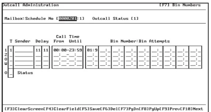
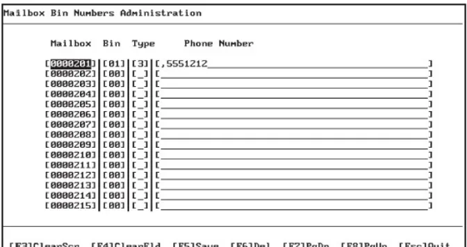
5 Outcall Administration... 5‐1 5.1 Outcall Administration Screen . . . 5‐1 5.2 Mailbox Bin Number Administration Screen . . . 5‐3
6 Voice Menu Programming... 6‐1 6.1 Voice Menu Boxes . . . 6‐1 6.2 Voice Menu Operation Overview . . . 6‐2 6.3 Voice Menu Box Routing Issues . . . 6‐4 6.4 DTMF Key Assignments . . . 6‐6 6.5 Special Auto‐Attendant Rules . . . 6‐8 6.6 Linking Voice Menu Boxes for Complex Menu Systems . . . 6‐9 6.7 Recording Voice Menu Greetings . . . 6‐10
7 Class of Service Administration ... 7‐1 7.1 Mailbox Class of Service Administration Screen . . . 7‐1
8 System Administrator Mailboxes ... 8‐1 8.1 Introduction . . . 8‐1 8.2 Mailbox Administration . . . 8‐6 8.3 System Group Lists . . . 8‐11 8.4 Utility . . . 8‐13 8.5 Operating Modes. . . 8‐14 8.6 Company Name. . . 8‐15 8.7 Network Administration . . . 8‐15
TC
9 System Features...9‐1 9.1 Answering Machine Emulation . . . 9‐1 9.2 Audio Text Response. . . 9‐1 9.3 Auto Attendant . . . 9‐2 9.4 Silent Record. . . 9‐2 9.5 Group Lists . . . 9‐3 9.6 Mailbox Linking . . . 9‐3 9.7 Message Reminder. . . 9‐3 9.8 Multi‐Extension Mailbox . . . 9‐4 9.9 Non‐Receipt Notification . . . 9‐5 9.10 Pager Notification . . . 9‐5 9.11 Secretary Mailbox Access . . . 9‐5 9.12 Time Sensitive Custom Greetings . . . 9‐6 9.13 Question and Answer Mailboxes . . . 9‐6 9.14 UCD Auto Attendant Overflow (Future Enhancement) . . . 9‐7 9.15 UCD Overflow Announcements . . . 9‐8 9.16 Intercom Paging . . . 9‐9
10 Special Keys & Screens...10‐1
11 Mailbox Group Administration...11‐1 11.1 Mailbox Group List Administration . . . 11‐1 11.2 Defining Group Lists . . . 11‐1 11.3 System Group Lists . . . 11‐2 11.4 Creating A System Group List . . . 11‐3 11.5 Personal Group Lists . . . 11‐6
12 System Reports...12‐1 12.1 General Information . . . 12‐1 12.2 Detailed Reports. . . 12‐2 12.3 Mailbox Directory Report . . . 12‐3 12.4 Mailbox Directory Uninitialized Report. . . 12‐4 12.5 Mailbox Summary Report . . . 12‐5 12.6 Mailbox Daily Detail Summary Report . . . 12‐6 12.7 Mailbox Daily Detail Report. . . 12‐7 12.8 Mailbox Report by Box . . . 12‐8 12.9 Survey Mailboxes. . . 12‐9 12.10 Port Statistics By Port. . . 12‐10 12.11 System Port Statistics. . . 12‐11 12.12 Hourly Port Statistics Report . . . 12‐12 12.13 Outcalling Detailed Report. . . 12‐13 12.14 Detailed Group List Reports . . . 12‐14 12.15 Personal Group List Report . . . 12‐15 12.16 Digit Grabber . . . 12‐16
13.5 Network Master Mailbox Directory . . . 13‐11
13.6 Network Monitoring. . . 13‐13 13.7 AMIS Job Reports . . . 13‐15 13.8 Testing The Network and Training Users . . . 13‐17
14 Remote Modem Programming ... 14‐1 14.1 Required Equipment . . . 14‐1 14.2 Modem Setup. . . 14‐2 14.3 Programming the Special Modem Commands. . . 14‐3 14.4 Restoring the Modem to Factory Default Settings Section . . . 14‐4
15 PC Terminal Setup ... 15‐1
16 Backup & Restore Procedures ... 16‐1 16.1 Overview . . . 16‐1 16.2 Supported Hardware . . . 16‐1 16.3 Backup Procedures . . . 16‐2 16.4 Iomega Zip or Jazz Drive . . . 16‐2 16.5 Backpack CD‐R . . . 16‐3 16.6 Imation Superdisk LS‐120 . . . 16‐4
In
tr
oduc
tion
1
1
Introduction
Suite 64 HD Voicemail is a sophisticated voice application generator using
state‐of‐the‐art hardware and software. All voice processing is handled by digital voice processing components on the card for the utmost in voice clarity and reliability. The software is a task‐oriented system that connects directly to the digital signaling bus in the Tadiran Suite 64 telephone system, allowing for extremely precise integration.
All programming is done through a series of easy‐to‐follow menus. Function key help menus are available on all screens.
Suite 64 HD Voicemail System Information And Capacity
Suite 64 HD Voicemail is a standalone unit which plugs directly into the Suite 64 PBX backplane for integration. Suite 64 HD Voicemail supports both large and small system applications. Suite 64 HD Voicemail offers virtually limitless mailbox
capacity through its flexible numbering plans.
Hardware Summary
• Common components:
• 486 compatible CPU
• latest DSP technology
• SMT component technology for maximum reliability
• Minimum 2.0GB hard drive
• 200 hours storage capacity
• power is supplied through the KSU backplane connector
• 4 megabytes of RAM
• 200 hours of voice storage capacity
In
tr
oduc
tion
1
Software Summary
• MS‐DOS 6.22 operating system
• Dialogic™ API‐compliant voice drivers
• Simplicity Voice Mail software
System Features
Suite 64 HD Voicemail systems come with a large set of standard and advanced Features as Outlined in Section 9 of this Manual.
Programming Equipment Required
Suite 64 HD Voicemail systems are shipped ready for immediate use using a default software configuration. This default configuration can be modified or completely reprogrammed to satisfy specific customer requirements.
Programming or maintaining the Suite 64 HD Voicemail configuration requires the
following equipment:
• An IBM‐compatible desktop or laptop computer with an available serial port • A communications software package capable of TVI950 terminal emulation ‐
Procomm Plus for Windows has been thoroughly tested and is recom‐ mended
Specific terminal software settings will need to be modified and some Function keys will need to be re-mapped - see Addendum 2 -Terminal Setup • 9‐pin male‐female straight‐thru serial cable
One of the following devices is required for Suite 64 HD Voicemail field‐installed software upgrades and data backups:
• 1.44MB MicroSolutions Backpack drive
• 120MB Imation SuperDisk drive
In
tr
oduc
tion
1
Reports
The Suite 64 HD Voicemail software can report on data for the previous 30 day period. The system contains a number of built‐in reports. These reports offer the technician or system administrator the ability to view various types of system information and data. Such information may be useful for troubleshooting and system analysis purposes. Please see Section 10 ‐ System Reports for additional information.
The purpose of this installation manual is to provide the information you need to bring a new Suite 64 HD Voicemail installation on‐line in the fastest time possible. Once you have the system up and running, the rest of this installation manual will provide all the details required for more sophisticated application questions.
The Suite 64 HD Voicemail Installation & Maintenance manual is divided into the following sections:
• Section 1 ‐ Introduction ‐ this section provides a general description of the
system, a description of this manual and the conventions used throughout. • Section 2 ‐ Installation Procedures‐ This section provides suggestions for the
preparations before installing the card and the actual installation of the card on the Suite 64 system.
• Section 3 ‐ System Programming ‐ This section provides descriptions of all of the programming screens with accompanying field descriptions.
• Section 4 ‐ Mailbox Programming‐ This section provides descriptions of all of the Mailbox programming screens and their use.
• Section 5 ‐ Outcall Administration‐ This section provides descriptions of all fo the Outcall Administration programming screens and their use.
• Section 6 ‐ Voice Menu Programming‐ This section provides descriptions of all of the Voice Menu box programming screens and their use.
• Section 7 ‐ Class of Service Administration‐ This section provides descrip‐ tions of all of the Class of Service programming screens and their use. • Section 8 ‐ System Administrator Mailboxes‐ This section provides descrip‐
tions of the programming screens and mailbox options available to the Sys‐
tem Administrator.
• Section 9 ‐ System Features‐ This section provides descriptions of the various features of the system.
• Section 10 ‐ Special Keys & Screens‐ This section provides descriptions of the use of special keys and “hidden” screens that are invariably used in pro‐ gramming.
• Section 11 ‐ Mailbox Group Administration‐This section provides descrip‐ tions of how the System Administrator establishes and maintains system and
In
tr
oduc
tion
1
• Section 12 ‐ System Reports‐ This section provides descriptions of the vari‐ ous reports that can be generated for management reporting.
• Section 13 ‐ Remote Modem Programming ‐ This section provides instruc‐ tions for using the Suite 64 HD Voicemail with a modem.
• Section 14 ‐ PC Terminal Setup‐ This section provides the parameters to setup Suite 64 HD Voicemail with Procomm.
• Section 15 ‐ Backup and Restore Procedures ‐ This section provides descrip‐ tions of backup and restoring data using various supported hardware. • Section 16 ‐ Special Applications ‐ This section provides descriptions of the
In
tr
oduc
tion
1
The following conventions are used throughout this manual.
Table 1-1 Conventions
1.3
Document Conventions
Convention Description
Normal Used in body text throughout this manual.
Normal, Italic Used in referencing sections, telephone features
and voice recordings or prompts.
Bold, Italic Used in describing the fields in PC screens and other form names or items.
Normal, Bold Used to describe filenames, device names and specific areas of PC screens.
Press Means to press a specific key. (e.g. press ESC
means to press and release the Escape key.)
Enter Means to type or push a button on the
telephone keypad.
123
(TelephoneKeys)
Indicates the keystrokes that are required to be entered on a telephone.
PC Keyboard Keys Indicated to show keystrokes required to be
In
tr
oduc
tion
1
The following documents should be used in conjunction with this manual:
• Suite 64 Deluxe Model Telephone User Guide (PN 72447010146) • Suite 64 Standard Model Telephone User Guide (PN 72447010147) • Suite 64 Flash Voicemail Installation & Maintenance Manual
• Suite 64 HD Voicemail Installation & Maintenance Manual
In
stallation
Pr
ocedur
es
2
2
Installation Procedures
Proper preparation is the cornerstone of a successful installation and will result in improved customer satisfaction. Taking a few moments now to secure the
necessary equipment, programming information and manpower requirements will
save you many hours of frustration during the course of the installation, as well as enhancing the customer’s perception of how the new system will work for them. In order to properly set up the system, you should make sure the following items are available BEFORE starting the initial setup:
• A system Voice Menu design plan that has been discussed with and approved by the end user.
• A well‐spoken person available to do the necessary recordings for the system greetings.
• A technician who is capable of doing any required PBX system program‐ ming.
• All required documentation for the PBX options programming.
You should plan to start the installation early enough in the day to allow sufficient time for customer changes, integration issues, etc. A good estimate is to allow 1‐2 hours for a complete installation, excluding the necessary time for training the end users.
Make sure to review this installation manual BEFORE the day of installation.
In
stallation
Pr
ocedur
es
2
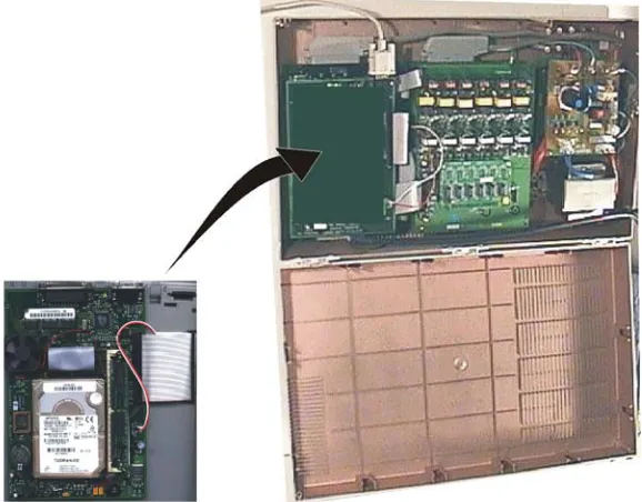
Install the Suite 64 HD Voicemail Voice Mail System card into the Suite 64 system as follows. Figure 2-1: Installation of Suite 64 HD Voicemail System Card can be used for reference.
Figure 2-1 Installation of the HD Voicemail System Card
2.2
Installing Suite 64 HD Voicemail
In
stallation
Pr
ocedur
es
2
1. Remove the 4 mounting screws from the CCB card and replace with the 4 standoffs supplied with the voicemail system card. Set the 4 mounting screws aside.
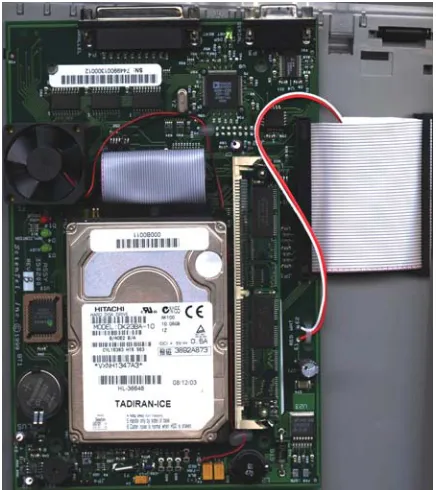
2. While holding the card close to the Suite 64 cabinet connect the ribbon cable with the receptacle on the CCB card and connect the red/white power line connector with the receptacle on the 610‐2 board.
3. Line up the 4 mounting holes on Voice Mail System card with the 4 stand offs on the CCB card. Firmly, secure the card to the CCB card with the 4 mounting screws previously set aside.
4. Power up the system and verify that the Voice Mail card green System Status LED’s at the top of the card is blinking.
5. Connect a 9‐pin serial cable male‐end to the female receptacle on the Voice Mail System card.
6. Connect the other end of the serial cable with the desired serial port on a laptop or PC.
The Voicemail System is now installed, synchronized and ready for programming on a laptop or PC. The card automatically starts up once it is inserted and receives power from the Suite 64 bus.
As the Voicemail boots up, you will see a series of screens open and close as the various drivers and programs load. Finally the port status screen will appear. The
Voicemail system is now installed and running.
All that is left is to program the user mailboxes and voice menu options. Refer to Sections 3 through 7 for detailed instructions on Voicemail system programming.
The figure below shows the various ports and indicator lights located on the Suite
In
stallation
Pr
ocedur
es
2
Figure 2-2 Suite 64 HD Voicemail Card-Front View
Suite 64 HD Voicemail requires no additional programming. The system
automatically configurs itself to operate with Suite 64 system when the card is installed and the system is turned on.
In
stallation
Pr
ocedur
es
2
Perform the following sequence of actions to properly shutdown the Suite 64 HD
Voicemail system:
1. Connect your programming PC system.
a. At the main status screen, press the
1
key and enter the system password(default is 1234).b. When the system menu appears, press 7 to shutdown the system.
c. A pop‐up screen appears and gives you the choice of an immediate or
friendly shutdown.
d. The friendly shutdown (
1
‐continue) waits until an in‐use port hangs up and then disables it. After all ports become disabled, the system then shuts down and exits to DOS.e. The immediate shutdown(
0
‐ Immediate) option, when selected,hangs up all ports immediately and exits to DOS.
In
stallation
Pr
ocedur
es
System
Pr
ogramming
3
3
System Programming
Suite 64 HD Voicemail is usually programmed via terminal emulation by using a computer connected through the DB‐9 connector on the Suite 64 HD Voicemail unit. The system administrator can also perform some programming functions through the System Administrator’s mailbox. Information on how to program Suite 64 HD
Voicemail using the System Administrator’s mailbox and keyset can be found in Section 3: System Administrator Mailboxes.
When moving about in the programming screens it is important to know how the navigational keys will work. All keys on the keyboard are active except for the Control (
C
) and (A
) keys. TheC
key is not used by the software. To press anA
‐key selection likeA
‐A
, press the!
key followed by theA
key.Different keys may be available for different screens. Always reference the bottom line of the screen for currently valid choices.
The following keystrokes may be used when navigating a screen:
t
. . . moves the cursor up one line at a timeb
. . . moves the cursor down one line at a timer
. . . moves the cursor to the next field or position in the field or linel
. . . . acts as a destructive backspace if the cursor is in a fieldI
. . . moves back one screenD
. . . moves back one screene
.. . . moves back one screenE
. . . returns to the previous menu screenT
. . . moves forward through each fieldR
. . moves forward through each fieldSystem
Pr
ogramming
3
3
. . . clears the screen and prepares a blank data entry record4
. . . clears the field where the cursor is currently placed5
. . . updates or saves information on the screen6
. . . deletes the current record on the screen after confirmation7
. . . moves to a sub‐window as described in the upper left corner8
. . . moves backward one screen after pressing7
9
. . . move to the previous data record0
. . . move to the next data record!
. . . performs a refresh of the screen displaySystem
Pr
ogramming
3
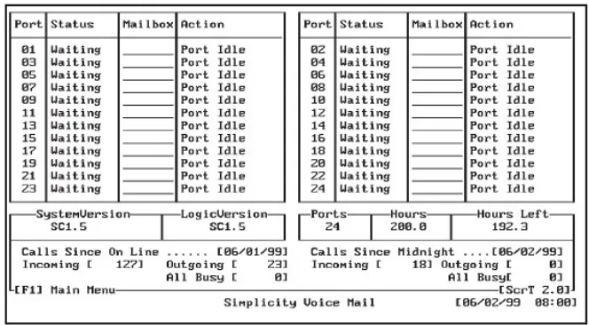
The Main Status Screen displays the current status of the active system ports, allows entrance to the system programming menus and allows the running of the clean up routine manually.
The lower section of the screen displays current statistical information about Suite
64 HD Voicemail.
Figure 3-1 Main Status Screen
Keystrokes Available from the Main Status Screen
The following function keys may be used at the Main Status Screen:
1
. . . . brings up the Enter Password window. (The default password of 0000may be changed.)
2
. . . . toggles the screen saver on and off3
. . . manually starts the Disk Cleanup process9
. . . prompts for a “Channel Number to Start”0
. . . . . prompts for a “Channel Number to Stop”System
Pr
ogramming
3
9
/
0
Key Notes
If a port, or ports, needs to be stopped or started Suite 64 HD Voicemail offers that ability. For example, if the disconnect codes have not been properly programmed, the ports will continue processing for an indefinite period of time, depending on what function Suite 64 HD Voicemail was performing when the hangup occurred. To stop this behavior, Press
0
and Suite 64 HD Voicemail will prompt for a “Channel Number to Stop.” Enter the port number that is off‐hook and pressR
. To stop or start all ports, enter 99 as the port number and then pressR
.Field Descriptions
The fields listed below are not programmable, however display important information about the current configuration of the system. This information may aid in troubleshooting a system fault.
Ports Status Section
Port ‐ This field indicates the voice mail port number (01 to 08). Ports 01 ‐08 will be active for a Suite 64 HD Voicemail system, depending on the ports ordered.
Status ‐ This information field displays the current activity for the specific port. Some of the functions that may be seen include Idle, Off‐hook, On‐hook, Playing, Get T.T. (Touch Tone).
Mailbox ‐ This field displays the mailbox number that is currently being accessed by the port. This entry could be either a subscriber mailbox or a voice menu mailbox. If no mailbox is in use, the field is empty.
Action ‐ This field displays the task/menu code that Suite 64 HD Voicemail is currently executing.
System Information Section
System Version ‐ Displays the currently installed version number of the
system software.
Logic Version ‐ Displays the currently installed version of the Task/Menu control files.
Ports ‐ Displays the number of voice mail ports that are available.
Hours ‐ Displays the total message storage capacity of the Suite 64 HD
Voicemail hard drive.
Hours Left ‐ Displays the amount of storage space currently available on the Suite 64 HD Voicemail hard drive.
Calls Since On Line Section ‐ These fields show information that is related to the last time the system was activated as shown in the Calls Since On Line
System
Pr
ogramming
3
Calls Since On Line . . . . . [DATE] ‐ This field and the following three fields contain the date the system was last powered on and statistics regarding the number of calls handled since that date.
Incoming ‐ Displays the total number of incoming calls that Suite 64 HD
Voicemail has received since being installed and the power turned on.
Outgoing ‐ Displays the total number of outgoing calls that Suite 64 HD
Voicemail has processed since being installed and the power turned on. i.e.
Pager outdials
All Busy ‐Displays the number of times that all ports were in use simultaneously since being installed and the power turned on.
Calls Since Midnight . . . . . [DATE] ‐ This field and the following three fields contain the current date of the system and statistics regarding the number of calls handled since midnight of that date.
Incoming ‐ Displays the total number of incoming calls that Suite 64 HD
Voicemail has received that day since midnight.
Outgoing ‐ Displays the total number of outgoing calls that Suite 64 HD
Voicemail has processed that day since midnight. i.e. Pager outdials
System
Pr
ogramming
3
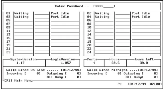
From the Main Status Menu press
1
and a password entry area will appear at the top of the Main Status Menu. Enter your password to access programming on this screen. (The default password is 1234). The password matches the SystemAdministrator’s mailbox password.
Figure 3-2 Main Status Screen-Password Entry
When the correct password is entered, the bottom portion of the Main Status Menu screen displays a group of programming menu choices.
Press the number next to the category you wish to program. When finished press 0 to return to the Main Status Menu window or press 7 to shutdown Suite 64
HD Voicemail. For more information, refer to Section 2: Shutting Down the System.
If Disk Clean Up is enabled on the Site Administration screen and Suite 64 HD Voicemail still has programming screens displayed, then Suite 64 HD Voicemail will not run the Disk Clean Up. The following error message will appear at the bottom of the screen: “Press any key to exit and run Clean Up.”
Suite 64 Voicemail will then run the clean up routine. Always remember to
exit the programming screens.
System
Pr
ogramming
3
Screen Saver
The system has a screen saver that engages when a screen is being displayed and no action is taken for five minutes. It is recommended that the
2
,t
, orb
keys be used when exiting the screen saver.Field Descriptions
Refer to the field desciptions on page 3-4.
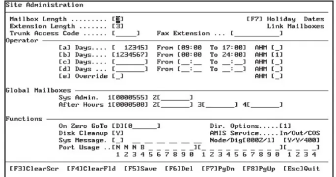
The Site Administration Screen, as shown below, sets a number of default parameters that the system will use. In the top half of the screen, you can set the number of digits for the mailbox numbers, telephone extension numbers, and
password minimum and maximum lengths.
Figure 3-3 Site Administration Screen
Field Descriptions
The following are fields on the Site Administration Screen:
Mailbox Length ‐ This value is the number of digits in a mailbox number. Default for Suite 64 HD Voicemail is three digits. All mailboxes in the system will normally have the same number of digits. Valid entries are two, three, four and five. Exceptions are the system control boxes as described later.
System
Pr
ogramming
3
Extension Length ‐ This is the maximum length of the extension numbers that will be dialed when a mailbox number is dialed from the Automated
Attendant function. This length should not be set to less than 2 digits and will normally match the Mailbox Length field.
Trunk Access Code ‐ This value tells Suite 64 HD Voicemail which trunk line to access in order to perform outbound dialing for system outcall operations. Valid entries may be individual trunk lines, or trunk group/route numbers including Least Cost Routing and overflow dialing groups. If this field is left blank, Suite 64 HD Voicemail places the digit ‘9’ in front of the telephone number and will access the next available trunk line.
Fax Extension ‐ Enter the extension number that is connected to the Fax machine that will be used to receive Fax calls routed through the Automated Attendant. When the Auto Attendant recognizes incoming Fax tones, it will transfer the call to this extension. Enter the characters &, followed by the
extension number.
For example: if the system Fax extension is 325 ‐ enter &, 325 in this field
Operator Schedule Section
When a caller dials Zero (0) to be transferred to an operator, the system determines the destination of this transfer based on three items:
1 ‐ where the caller is in the voice mail system
2 ‐ the current day of the week
3 ‐ the current time of day
If the caller is in a Voice Menu or in a subscriber mailbox (type 1‐5) with an “On Zero GoTo” entry filled in and dials 0, the system will send the caller to the programmed destination. If neither of these first two options have a valid destination, or the caller presses 0 from anywhere else in the voice mail, the system will check and use the Operator entry fields on this screen to
determine the destination of the request for the Operator.
To make this decision, the system first looks at the Override field:
1. Override field is set to “Y” ‐ The system checks the AHM (After Hours Mailbox) field on that line. If the AHM field is empty, the system will transfer the caller to the destination specified in the “On Zero GoTo” entry in the Functions area.
System
Pr
ogramming
3
2. Override field is set to “N” or is blank ‐ The system compares the day of week and time of day to the entry line entries [a] through [d], starting at [a] and moving down, checking on each line until a match is found. When a match is found, the system looks at the corresponding AHM field to determine the actual destination of the transfer. If the AHM field is blank, the system will transfer the caller to the destination specified in the “On Zero GoTo” entry in the Functions area.
If the AHM field is programmed with a number from 1 through 4, the system will transfer the caller to the mailbox destination specified in the appropriate After Hours Mailbox as programmed in the Global Mailboxes area.
Lines a‐d determine the schedule of Operator assignments. Each line has three component fields that make up the schedule line:
Days ‐ Valid entries in the Days fields are blank or any combination of the digits 1‐7, which represent Sunday(1) through Saturday(7).
From and To ‐ These are the times that this line is considered to be active. The From and To entries are both entered in 24 hour format. Blank is a valid entry.
AHM ‐ Enter the desired AHM mailbox number to be used for this time period. Valid entries are from 1 ‐ 4. These assignments are made in the Global
Mailboxes Section.
Global Mailboxes Section
Sys Admin. ‐ Suite 64 HD Voicemail allows the programming of two different system administrator mailboxes. The second administrator mailbox is
convenient when there may be a secondary administrator who needs access to system programming in the absence of the primary System Administrator. Sys Admin. 1 is the default mailbox used by the system administrator to access the system and is set in default programming as Mailbox 555. See the System Administrator section and guide for more information on setting up the
System Administrator mailbox.
After Hours ‐ These fields provide the destinations for any After Hour Mailbox(AHM) assignments that have been made in the Operator Schedule Section. Valid entries are existing mailboxes on the system.
Functions Section
On Zero GoTo ‐ This field is utilized by the operator schedule when the AHM entry is left empty. There are two sections. The first section may contain a D for dialing a telephone system extension or an M for sending the caller to a mailbox. The second section contains either the extension or mailbox
System
Pr
ogramming
3
Disk Cleanup ‐ Suite 64 HD Voicemail can be programmed to automatically perform a disk cleanup on the hard drive subsystem every day. In default programming, this option is set to “Y” which enables disk clean up. If this field is left empty or set to “N” then this feature is disabled. The cleanup routine is set from the factory to run at 2:00 A.M. every day.
The disk clean up routine performs several functions:
• The system checks all mailboxes for messages and then resets all Message Waiting Indicators to the correct mode, either ON if there are still new unheard messages or OFF if there are no new messages and/or only saved messages in the mailbox
• The storage date of all messages is then checked to see if any messages have reached the maximum number of days allowed according to the mailbox’s Class of Service. For all mailboxes with messages that have reached the maximum number of days allowed, an auto erase alert message is sent to the Subscriber.
• Suite 64 HD Voicemail then automatically performs a system shutdown and exits to DOS.
• The Disk Cleanup routine then runs the SCANDISK utility on the Suite 64
HD Voicemail hard drive and corrects any problems that might be found.
• The Disk Cleanup routine then runs the DEFRAG utility on the Suite 64 HD
Voicemail hard drive and compacts the message storage area. This keeps the
system running quickly.
• Suite 64 HD Voicemail is then automatically restarted and comes on‐line
Depending on the size of the hard drive, the number of messages stored on it and any possible disk problems that may be found, a normal Disk Cleanup routine can take anywhere from 3 minutes up to approximately 30 minutes.
System Message ‐ This is an informational field that lets the System
Administrator know if there is a system wide broadcast message in effect. No entries need to be made in these fields for a broadcast message to be sent to all mailbox subscribers.
However, if a PLUS is displayed signifying a broadcast message is in effect, then changing it to MINUSwill disable the broadcast message notification in the subscribers’ mailboxes. The broadcast message, however, will not be deleted when the field is changed to MINUS. Message notification to
System
Pr
ogramming
3
A broadcast message is only deleted when a new broadcast message is recorded by the System Administrator, or the System Administrator manually deletes it. This is helpful when the same broadcast message needs to be sent at various times during the year. The message does not have to be re‐recorded, just re‐activated Port Usage ‐ This field determines how a port is used for outcalls, message waiting indicator(MWI) notification or neither function. Entries are only required for installed equipment ports (1‐24).
The four valid field entries are:
N ‐ indicates that this port will not be used for Outcalls or Message Waiting
O ‐ indicates that the port will be used for Outcalls only
M ‐ indicates that it will be used for Message Waiting only
B ‐ indicates that the port will be used for both Message Waiting and Outcalls
Directory Opt. ‐ This field determines whether the first or last name prompt is used with the Dial By Name Directory feature.
If the field is empty (the default) or contains a “1,” the system uses the last name for directory searches.
System
Pr
ogramming
3
The Holiday Dates Administration Screen is reached by pressing
7
while in theSite Administration Screen.
Holiday Dates allows for the programming of recurring dates that require special greetings to be played to the caller. Each date can have its own greeting and menu structure or all dates can use the same greeting and menu structure. It is
recommended that Holiday Dates table that contain traditional holidays such as July 4 or December 25 be re‐programmed each year.
To access the Holiday Dates screen, use the
7
key while in the SiteAdministration Screen.
Figure 3-4 Holiday Dates Administration Screen
FIeld Descriptions
The following are fields on the Holiday Dates Administration Screen:
Table No ‐ This field contains the port number and the table number assigned to the port(s). Port numbers can be assigned in two ways. A single port may be designated i.e. 01, or 99 can be entered to designate that all ports will use the same table.
System
Pr
ogramming
3
Enter the port number or 99 for all ports. After the colon enter the table number.
Multiple pages of tables are accessed by scrolling with the
7
and8
keys.Start Date – Time ‐ Enter the date and the time that this holiday schedule is to begin.
Until Date – Time ‐ Enter the date and the time that this holiday schedule is to end.
Action ‐ This field tells Suite 64 HD Voicemail what to do when the schedule is activated. The action can be sending a caller to a pre‐recorded Voice Menu (C) or the caller can be sent directly to a designated mailbox (M). For example C‐81, 1 sends the caller to Voice Menu 81, greeting 1 where the caller may make menu choices; M‐0000200 sends the caller to mailbox 200 to take a message.
Comments ‐ This field allows a description of the action that Suite 64 HD
Voicemail is to perform. This is for programming information only and has no effect on operation of the holiday schedules.
Recommendations
The Start Time should be the time when your company closes for the holiday and the Until Time would be when your company re‐opens for regular business.
System
Pr
ogramming
3
Suite 64 HD Voicemail features the ability to allow a variety of message transfers
between mailboxes.
There are four Link Types available to serve different applications.
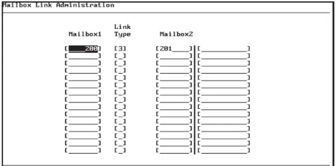
Each individual link is one way and goes from one mailbox to another mailbox or from one mailbox to a system group list. The mailbox specified in Mailbox 1 will hear a standard prompt informing the subscriber that their mailbox is linked to another mailbox/group. This prompt is played for Mailbox 1 no matter what link type is active. To delete an entire mailbox link, position the cursor anywhere on the line and press the
6
(Delete) key.Figure 3-5 Mailbox Link Administration Screen
System
Pr
ogramming
3
When programming mailbox links be careful not to create a “loop” that causes Suite 64 HD Voicemail to appear locked up. For example: Create a link between Mailbox 201 and Mailbox 202 using a type 3 link. Create a link between Mailbox 202 and Mailbox 201 using a type 3 link. Now leave a message for either 201 or 202. Because of the incorrect link programming, each time a message is saved in one of the mailboxes, it is copied to the linked mailbox, which triggers the link back to the original mailbox. The system will now be stuck in a loop and attempt to leave the same message infinite times. Suite 64 HD Voicemail will no longer respond to programming commands and it will not answer other ports. Always check links carefully to insure this scenario does not happen.
When modifying a mailbox link delete (
6
) the original entry. If the original entry is not deleted, then there will be two entries - the original entry and the modified entry.Field Descriptions
The following are fields on the Mailbox Link Administration Screen:
Mailbox 1 ‐ Enter the mailbox number that will link to another mailbox/group.
Link Type ‐ Enter the type of link (1 ‐ 4) as defined below:
Link Type 1: Direct Mailbox ‐ A Direct Mailbox links one mailbox to another and directs all messages to the second mailbox of the link. The two mailboxes utilize mailbox 2’s greeting and messages are stored and retrieved from mailbox 2. The Message Waiting Indicator (MWI) associated with Mailbox 2 will light. Subscribers who enter mailbox 1 hear a prompt informing them that it is linked to Mailbox 2.
When the subscriber enters mailbox 1 the Suite 64 HD Voicemail announces: “Messages being sent to your mailbox are automatically copied to . . . (the system plays the linked-to mailbox subscriber’s name).”
System
Pr
ogramming
3
When the subscriber enters mailbox 1 the Suite 64 HD Voicemail announces: “Messages being sent to your mailbox are automatically copied to . . . (the system plays the linked-to mailbox subscriber’s name).”
Link Type 3: Supervisor’s Link ‐ This type links one mailbox to another and directs a copy of all messages sent to the first mailbox on to the second mailbox and lights the MWI for both mailboxes. When outside callers dial mailbox 1, they will hear the name and greeting for mailbox 1. And when a message is left, the message will go to mailbox 1, with a copy directed without comments to mailbox 2. The Message Waiting Indicator (MWI) associated with both mailboxes will light. If mailbox 1’s subscriber deletes the message in mailbox 1, there will still be a new message waiting to be heard in mailbox 2.
When the subscriber enters mailbox 1 the Suite 64 HD Voicemail announces: “Messages being sent to your mailbox are automatically copied to . . . [the system plays the linked-to mailbox subscriber’s name].”
Link Type 4: Overflow Link ‐ This type links one mailbox to another so that when the first mailbox becomes full, new messages go the second mailbox.
It is important to know that the maximum number of messages in any mailbox is the total number of new messages and future delivery messages. This total is the result of combining the Max No Of Messages field and the Max Future Messages field on the Class of Service Screen for the mailbox. When outside callers dial mailbox 1, they will hear the name and greeting for mailbox 1. If mailbox 1 is not full (as defined by the Max Number Of
Messages in the Class of Service) and a message is sent, the message will go to mailbox 1 and the Message Waiting Indicator (MWI) associated with mailbox 1 will light. If mailbox 1 is full and a message is sent, the message will go to mailbox 2 and the Message Waiting Indicator (MWI) associated with mailbox 2 will light. When callers dial mailbox 2, they will hear the name and greeting for mailbox 2. And when a message is sent, the message will go to mailbox 2 and the Message Waiting Indicator (MWI) associated with mailbox 2 will light.
Mailbox
Pr
ogramming
4
4
Mailbox Programming
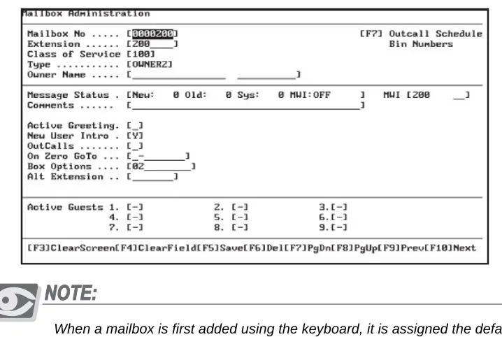
The Mailbox Administration Screen is used to add, modify or delete individual subscribers’ mailboxes. The screen has fields to assign a mailbox’s Type, Class of
Service and the Owner Name of the mailbox subscriber. The Owner Name is used by the Dial by Name directory feature. Both of the System Administrator
Mailboxes are also set up using this screen.
Figure 4-1 Mailbox Administration Screen
When a mailbox is first added using the keyboard, it is assigned the default password of 0000.
This default password is needed to access the mailbox for the first time. When Subscribers access their mailbox for the first time, the system takes them through a setup tutorial. During this tutorial, the mailbox subscriber is required to enter a new, different password. If the mailbox subscriber forgets the new password, the system administrator can reset the password using the System Administrator’s mailbox functions.
Mailbox
Pr
ogramming
4
Default Mailbox Programming
There are several mailboxes that have been pre‐programmed into the system at the factory. They are:
500 General Delivery Mailbox
555 System Administrator Mailbox
900‐906 System Control Mailboxes ‐ DO NOT DELETE OR MODIFY
Adding Subscriber Mailboxes
It is always a good idea to coordinate with the customer and design the system plan before attempting to program the Suite 64 HD Voicemail system. The following information should be gathered from the customer before beginning to add mailboxes:
1. Determine the digit lengths for both the Mailbox and Extension numbers and make sure they are entered correctly in the Site Administration screen. These are usually the same length, but may be different.
2. List the Class of Service and Mailbox type that will be assigned to each
subscriber mailbox.
3. List mailboxes where Multiple Message Waiting Indicators will need to be assigned.
4. List mailboxes where Outcall dialing will be required and the numbers that need to be dialed. Also check if they are home or beeper numbers.
5. List mailboxes that will require a dedicated “Dial Zero” option and record
the destination number.
6. Decide which programmable options will be required for each mailbox.
7. Make a list of any special mailboxes that will be required; i.e. Question & Answer, Bulletin, Status, etc.
Mailbox
Pr
ogramming
4
Field Descriptions
The following are fields on the Mailbox Administration Screen:
Mailbox No ‐ This is the number the system will use to access this mailbox. The length of the mailbox number can be up to seven digits. Default length for the Suite 64 HD Voicemail system is three digits.
Existing mailbox numbers cannot be edited. The data for any mailbox, however, can be edited (see note above concerning mailboxes 900‐905).
To add a new mailbox, press the
3
key and enter “Y” when prompted “Clear Screen?” Enter the new mailbox number. If it has not yet beenprogrammed, Suite 64 HD Voicemail will prompt “Information Not Found. F1
for Closest. Enter To Continue.” Press
R
to accept the new mailbox number and continue programming the mailbox. If you press1
, you will be sent to the closet mailbox to the number you entered.Mailbox Range Programming:
To add a range of mailboxes, add the first new mailbox number of the range needed as above. After saving, press the key combination
@
+A. Suite 64 HDVoicemail will prompt:
Input Range of Mailbox, [ICExxxxxxx‐xxxxxxx]
Type ICE followed by the starting mailbox number, a dash (‐), the ending mailbox number and then press the
R
key. Be sure not to add any spaces in the information being typed.For example: enter [ICE000200‐000299] to add mailboxes 200 through 299
The system will prompt you if you would like the program to allow you to add the mailbox names as they are added. Select Y if you wish to enter names now or N to enter them later.
Extension ‐ This is the physical extension number associated with a specific mailbox that is dialed by the system when using the Automated Attendant transfer. If this mailbox is going to be assigned to take messages ONLY and there will be no physical extension, place a MINUS in this field. Do this with ALL Voice Menu mailboxes, Bulletin Board mailboxes and any other that will not transfer to a physical extension.
Class of Service ‐The number of the Class of Service that has been assigned to this mailbox. The Class of Service determines the individualized features and settings that a given mailbox will use. Suite 64 HD Voicemail comes with default COS 100, 400 and 700. COS 100 is for general subscriber mailboxes; COS 400 is for AMIS type mailboxes and COS 700 is for the system
Mailbox
Pr
ogramming
4
Type ‐ This field contains the mailbox type definition that has been assigned to this mailbox. The type definition determines how a mailbox will function and the task it is to perform.
The mailboxes in Suite 64 HD Voicemail can perform a myriad of special functions in addition to the routine tasks of transferring callers and taking messages. The following list describes each of the available mailbox types and how to set them up in system programming. Any special requirements are noted.
Example: A Question and Answer mailbox’s function is to play pre‐programmed questions and record callers answers.
The following table lists the available mailbox types with a brief description of the
functionality provided:
Mailbox
Type Description
1 This is a subscriber mailbox that uses all normal system prompts 2 This is a subscriber mailbox that does not play system prompts, it
just provides the tone to begin recording a message.
3 This is a subscriber mailbox that uses all normal system prompts and plays the recorded Company Name before the mailbox greeting.
4 This is a subscriber mailbox that plays the recorded Company Name followed by the mailbox greeting, but no system prompts are played, it just provides the tone to begin recording a message. 5 This is a subscriber mailbox that plays the mailbox greeting and
the caller is given a choice of dialing one (1) to leave a message or zero (0) to reach the operator. If nothing is dialed, the caller automatically transfers to the operator as defined by the Mailbox
ON ZERO GOTO field or if there is no entry there, the ON
ZERO GOTO field in the Site Administration screen.
6 This is a mailbox where there are no greetings when accessed. All the caller will hear is a beep to begin recording.
11 Question and Answer mailbox that confirms a caller’s answers by repeating the recorded answer capabilities. You may record up to 99 questions to be answered. See Notes 1 & 2 below.
12 Question and Answer mailbox that confirms a caller’s answers without repeating the recorded answers. You may record up to 99 questions to be answered. See Notes 1 & 2 below.
13 Question and Answer mailbox that just present questions, records the callers’ answers and then hangs up. You may record up to 99 questions to be answered. See Notes 1 & 2 below.
14 This mailbox plays a special greeting *** IN DEVELOPMENT