PREDICTION OF ENGINEERING
CONSTNATS OF CARBON T300/ EPOXY
COMPOSITE USING SOFT COMPUTING
Syed Altaf Hussain
1, Pandurangadu.V
2, Amba Prasad Rao .G
3Professor, School of Mechanical Engineering, RGM College of Engineering & Technology, Nandyal-518501, A.P,1 Professor, Department of Mechanical Engineering, JNTUA College of Engineering, Anantapur-515002, A.P, India 2 Professor, Department of Mechanical Engineering, National Institute of Technology, Warangal-506004, A.P, India 3
Abstract: The present work deals with the micromechanical analysis of carbon (T300) fiber reinforced in epoxy resin whose fiber volume fraction vary from 20%70%. A three- dimensional model with necessary boundary conditions has been developed from the unit cell of square pattern of the composite to predict the engineering constants like longitudinal young’s modulus (E1) , Transverse modulus (E2), major poisson’s ration 12 and In-plane shear modulus
(G12). The problem was modelled using ANSYS software and the results obtained from FE model was validated with
the bench mark results. In this work an attempt has also been made to develop the fuzzy logic rule based model to predict the engineering constants of carbon (T300) fiber reinforced epoxy composite. From the results it was concluded that fuzzy logic model can be effectively used to predict the engineering constants of fiber reinforced composites.
Keywords: : Cabon fiberT300, Fuzzy logic, FEM, Micromechanics.
I. INTRODUCTION
In recent years, fiber reinforced plastics (FRPs) are continuously replacing traditional engineering materials because of their superior advantage over other engineering materials. The advantages include high strength to weight ratio, high fracture toughness, and excellent corrosion and thermal resistance. The fiber reinforced plastic (FRP) composites are being extensively used in various fields like Aerospace, Automobile, Chemical industries, Off shore power plants, Refinery, Oil and Gas, Pulp and paper, Waste and waste water etc,. Fiber reinforced composites are basically inhomogeneous and anisentropic in nature due to this reason their analysis is more complex than that of conventional materials [1]. The mechanical properties of long fibre composites, such as stiffness, can be predicted using several prediction schemes such as the “Rule of Mixtures” and the Halpin-Tsai equations [2, 3]. Reference Works, Comprehensive Composite Materials, Elsevier 2000.A great number of micromechanical models have been proposed in the literature [4-5] for predicting various mechanical properties of composite materials. Hussain et.al [6] have made investigation on unidirectional continuous fiber lamina at different fiber volume fractions to predict engineering constants of FRP composite using the finite element method. Robertson et al [7] has presented the formulation of a new 3-dimensional micromechanical model for fiber reinforced composite material. Krishna Vihari[8] adopted micromechanical approach to predict the stresses at the fiber-matrix interface of Boron/S-G/E-G fiber and Epoxy matrix composites due to temperature gradient across the lamina. Dragan, [9] has studied the stresses in the unidirectional carbon/epoxy composite material using Finite Element Method (FEM), can be used in order to predict stress distribution on the model. Anifantis [10] has predicted the micro mechanical stress state developed within fibrous composites that contain a heterogeneous inter phase region by applying finite element method to square and hexagonal arrays of fibers.
In this paper finite element method is adopted for predicting engineering constants of Carbon (T300)/ Epoxy composite viz,. E1, E2, 12, and G12 and the results are compared with the results obtained from the rule of mixture and
unit cell is adopted for the analysis. The measure of the volume of fiber relative to the total volume of the composite is taken from the cross sectional areas of the fiber relative to the total cross sectional area of the unit cell. This fraction is considered as an important parameter in composite materials and is called fiber volume fraction (Vf). Fig.2 shows an
isolated unit cell.
Fig. 1Concept of Unit Cell
Fig. 2 Isolated unit cell of square packed array A. Finite Element Model
Fig. 3One-fourth portion of unit cell Fig. 4Finite Element mesh
The radius of the fiber is varied corresponding to the fiber volume fraction. For example, the radius of the fiber is calculated as 61.8units, for fiber volume fraction 30%.
B. Analytical solution
The mechanical properties of the lamina are calculated using the following expressions of Theory of elasticity approach and Halphin - Tsai’s formulae.
Young’s Modulus in the fiber direction and transverse direction E
1 = σ1/ε1
E
2 = σ2/ε2
Major Poison’s ratio ν
12 = - ε2/ε1
where σ
1 = Stress in x-direction ε1 = Strain in x-direction
σ
2 = Stress in y-direction ε2 = Strain in y-direction
C. Rule of mixtures
The Engineering constants of fiber reinforced composites can be determined using the following expressions. Longitudinal modulus: E1= Ef.Vf + Em. Vm
Transverse modulus 1/E2 = Vf/Ef + Vm/ Em
Major Poisson’s ration ν
12= νf VF + νm Vm
In-plane shear modulud 1/G12 = Vf/Gf + Vm/ Gm
D. Halphin-Tsai
The values obtained for transverse young’s modulus and in-plane shear modulus through equations (6) and (8) do not agree with the experimental results. This establishes the need for better Modeling techniques, which include finite element method, finite difference method and boundary element methods. Unfortunately, these models are available for complicated equations. Due to this, semi-empirical models have been developed for the design purposes. The most useful of these semi-empirical models includes those of Halphin and Tsai, since they can be used over a wide range of elastic properties and fiber volume fractions. Halphin and Tsai developed their models as simple equations by curve fitting to results that are based on elasticity. The equations are semi-empirical in nature since involved parameters in the curve fitting carry physical meaning.
Longitudinal Young’s Modulus (E1)
The Halphin-Tsai equation for the longitudinal Young’s modulus is the same as that obtained through the strength of materials approach, that is,
E
1 = Ef Vf + Em Vm
The transverse Young’s modulus, E
2, is given by
E
2/Em = (1+ξηVf)/ (1-ηVf)
Where η = ((E
f/Em)-1)/ ((Ef/Em) +ξ)
The term “ξ”is called the reinforcing factor and depends on the following;
Fiber geometry
Packing geometry
G
12/Gm=(1+ξηVf)/(1-ηVf)
where η = ((G
f/Gm)-1)/((Gf/Gm) + ξ
The value of reinforcing factor ξ depends on fibre geometry, packing geometry and loading conditions E. Fuzzy rule based modelling
Fuzzy logic has rapidly become one of the most successful of today's technologies for developing sophisticated control systems. Fuzzy logic (FL) has been used in many practical engineering situations because of its capability in dealing with imprecise and inexact information. The powerful aspect of fuzzy logic is that, it mimics the human decision making with an ability to generate precise solutions from certain or approximate information. The combination of incomplete, imprecise information and the imprecise nature of the decision-making process make fuzzy logic very effective in modeling complex engineering, business, finance and management systems which are otherwise difficult to model. Fuzzy systems make its decisions on inputs and outputs in the form of linguistic variables. The variables are tested with IF-THEN rules, which produce one or more responses depending on which rules they are asserted. The response of each rule is weighed according to the degree of membership of its inputs and the centroid of the responses is calculated to generate the appropriate output [11&12]. Figure 5 shows the fuzzy inference system, it is also known as fuzzy rule based system. Basically it consists of four functional blocks. Fuzzifier maps the input and output numbers into corresponding fuzzy memberships. Fuzzifier takes the input and determines the degree to which they belong to each of the fuzzy sets via membership functions. Inference engine is used for fuzzy reasoning and to generate fuzzy values. The defuzzifier converts the fuzzy sets in to crisp numbers. The rule base contains linguistic rules that are provided by expert. It is also possible to extract rules form the numeric data.
Fig. 5 Fuzzy Inference system
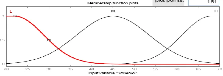
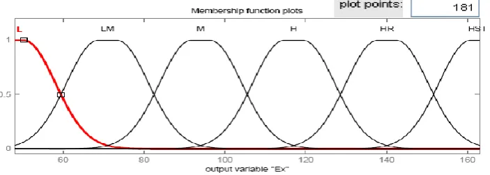
For fuzzy modelling, all numeric values were replaced with linguistic values. The meaningful linguistic statements are selected for the variable and expressed by appropriate fuzzy sets such as “low”, “Medium” and “high” for the fiber volume fraction. The numbers of member ship functions used for the output response are six, such as “ Low, “Low -medium”, “Medium”, “ High’, “Higher” and “Highest”. More precise results can be obtained by using more number of membership functions and hence, six membership functions were selected for the present investigation. In this investigation gauss2 membership function was considered..
Fig. 7 Membership function of longitudinal modulus (E1)
Fig. 8 Fuzzy rule viewer for longitudinal modulus (E1)
Figure 6 shows the membership function for the input variable i.e, fiber volume fraction, figure 7 shows the membership function for the output response longitudinal modulus (E1) and the figure 8 shows the fuzzy rule viewer.
To validate the developed fuzzy model, the predicted values are compared with the values determined using FEM.
III.RESULTSANDDISCUSSIONS
In this investigation the longitudinal modulus (E1) of carbon T300/ Epoxy composite was validated with the results
obtained from the rule of mixture. It was found that, there is very close agreement. Later on finite element method was applied to evaluate the other engineering constants like Transverse modulus (E2), Major-Poisson’s ratio (ν12) and
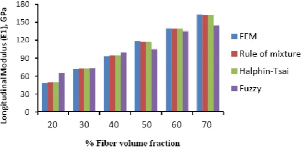
Fig. 9 Comparison of Longitudinal modulus (E1)
Fig. 10 Comparison of Transverse modulus (E2)
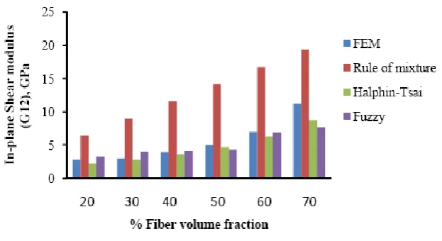
Fig. 12 Comparison of In-plane shear modulus A. Analysis of CarbonT300/ Epoxy composite
The variation of different engineering constants of a uni-directional Carbon T300/Epoxy composite with respect to the different fiber volume fractions are shown from Fig.13~16.
Fig. 13 Variation of E1 with the fiber volume fraction
0 40 80 120 160 200
0 10 20 30 40 50 60 70 80
E1
(GP
a)
% Fiber volume fraction
FEM
Rule of mixture
Haphin-Tsai
Fuzzy
0 10 20 30 40
0 10 20 30 40 50 60 70 80
E2
(G
P
a
)
% Fiber volume fraction
FEM
Fig. 15 Variation of ν
12 with the fiber volume fraction
Fig. 16 Variation of G
12 with the fiber volume fraction
B. Analysis of Results
Figures 13-16 show the variation of various engineering constants with respect to the fiber volume fraction. The observations are made from the plot are:
1. The longitudinal young’s modulus and (E1) and the Transverse modulus (E2) increases linearly with
increase in fiber volume fraction.
2. The Major Poisson’s ratio (12) decreases slightly with increase in the fiber volume fraction.
3. The In-Plane shear modulus (G12) increases linearly with increase in the fiber volume fraction 0f 50%,
there after it increases rapidly.
From the above results it was inferred that, Fuzzy predicted values are very close to the values determined by three-dimensional FEM model.
IV.CONCLUSIONS
The Micromechanical analysis of uni-directional CarbonT300 fiber reinforced epoxy composite has been performed using three-dimensional FEM model. The Engineering constants like Longitudinal young’s modulus (E1), Transverse
young’s modulus (E2), Major poisson’s ratio(12) and In-Plane shear modulus (G12) are predicted for different fiber
volume fractions. Fuzzy rule based model has been developed to predict the engineering constants. Based on the observed results it has been concluded that the fuzzy logic rule based model can be effectively used to predict the engineering of fiber reinforced composites.
0 0.05 0.1 0.15 0.2 0.25 0.3 0.35
0 10 20 30 40 50 60 70 80
12Fiber volume fraction %
FEM
Rule of Mixture Halphin -Tsai Fuzzy 0 5 10 15 20 25
0 10 20 30 40 50 60 70 80
G12
(GPa
)
Fiber folume fraction %
FEM
ACKNOWLEDGMENT
The author would like to thank School of mechanical engineering for extending the facilities for the research work.
REFERENCES
[1] Issac M. Daniel and Ori Ishai.. Engineering Mechanics of Composite Materials. Oxford university press. 1994.
[2] D. Hull, T.W. Clyne “An Introduction to Composite Materials”, Cambridge University Press, Cambridge, (second edition).
[3] M.W. Hyer, A.M. Waas “Micromechanics of Linear Elastic Continuous Fiber Composites”,
[4] Mc Cullough R.L. Micromodels for Composite Materials ¾ Continuous Fibre Composites. In: Delaware Composite Design
Encyclopaedia. Vol.2, Technomic Publishing Company. 1990.
[5] J C Halpin J C. Primer on Composites Materials Analysis. 2
nd
Edition. Lancaster: Technomic. pp.153-192. 1992.
[6] Syed Altaf Hussain, B. Sidda Reddy and V. Nageswara Reddy, “Prediction of elastic properties of FRP composite lamina for
longitudinal loading”, Asian Research Publishing Network (ARPN), vol. 3(6), pp. 70-75, 2008.
[7] Robertson, D. D. and Mall, S., “Fiber-Matrix Interphase Effects upon Transverse Behavior in metal-Matrix Composites”, Journal of
Composites Technology & Research, JCTRER, vol.14 (1), pp. 3-11, 1992.
[8] Krishna Vihari. N, Phani Prasanthi.P and. Bala Krishna Murthy. V, “Micromechanical Analysis of FRP Composites Subjected to
Thermal Loading‖ International Journal of Mechanics and Solids, Vol. 6, Number 3 pp. 167-174, 2011.
[9] Dragan D. Kreculj, “Stress Analysis in a Unidirectional Carbon/Epoxy Composite Material”, FME Transactions, Vol. 36 (3), pp.
127-132, 2008,
[10] Anfantis NK, Composite Science Technology,vol. 47, pp.289-301, 1993.
[11] Zadeh L., “Fuzzy sets”, International Journal of Information and Control, Vol. 8, pp. 338-353, 1965,
[12] Oguzhan Yilmaz, Omer Eyercioglu and Nabil N.Z. Gindy, “A user-friendly fuzzy-based system for the selection of electro discharge
machining process parameters”, Journal of Materials Processing Technology, Vol. 172, pp. 363-371, 2006.