Run Control Software for the Upgrade of the
ATLAS Muon to Central Trigger Processor
Interface (MUCTPI)
Ralf Spiwoks1,*, Aaron Armbruster1, German Carrillo-Montoya1, Magda Chelstowska1, Patrick Czodrowski1, Pier-Olivier Deviveiros1, Till Eifert1, Nick Ellis1, Philippe Farthouat1, Gorm Galster1,2, Stefan Haas1, Louis Helary1, Predrag Kuzmanovic1, Orestis Lagkas Nikolos1, Antoine Marzin1, Thilo Pauly1, Vladimir Ryjov1, Kristof Schmieden1, Marcos Silva Oliveira1, Joerg Stelzer1, Paschalis Vichoudis1, Thorsten Wengler1
1CERN, Switzerland 2NBI Copenhagen, Denmark
Abstract. The Muon to Central Trigger Processor Interface (MUCTPI) of the ATLAS experiment at the Large Hadron Collider (LHC) at CERN is being upgraded for the next run of the LHC in order to use optical inputs and to provide full-precision information for muon candidates to the topological trigger processor (L1TOPO) of the Level-1 trigger system. The new MUCTPI is implemented as a single ATCA blade with high-end processing FPGAs which eliminate double counting of muon candidates in overlapping regions, send muon candidates to L1TOPO, and muon multiplicities to the Central Trigger Processor (CTP), as well as readout data to the data acquisition system of the experiment. A Xilinx Zynq System-on-Chip (SoC) with a programmable logic part and a processor part is used for the communication to the processing FPGAs and the run control system. The processor part, based on ARM processor cores, is running embedded Linux prepared using the framework of the Linux Foundation's Yocto project. The ATLAS run control software was ported to the processor part and a run control application was developed which receives, at configuration, all data necessary for the overlap handling and candidate counting of the processing FPGAs. During running, the application provides ample monitoring of the physics data and of the operation of the hardware. *
1 The ATLAS Experiment at the LHC
The ATLAS experiment is a general-purpose experiment at the Large Hadron Collider (LHC) at CERN [1]. It observes proton-proton collisions at an energy of 13 TeV. With about 39 interactions in every bunch crossing (BC) every 25 ns, there are more than 109
interactions per second. The trigger system selects those events which are interesting to
* Corresponding author: [email protected]
physics and which can be recorded to permanent storage at a reasonable rate. The ATLAS trigger system consists of a Level-1 trigger based on custom electronics, which reduces the event rate to a maximum of 100 kHz, and a high-level trigger system based on commercial computers, which reduces the event rate to around 1 kHz on average.
2 The Level-1 Trigger System
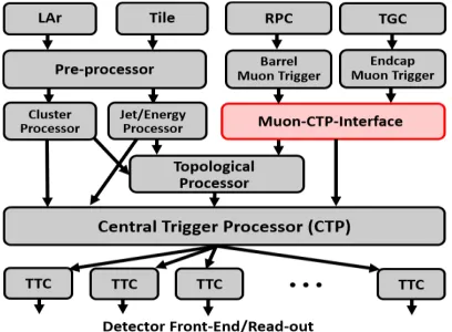
The first-level trigger of the ATLAS experiment uses reduced-granularity information from the calorimeters and dedicated muon trigger detectors, see Figure 1. The trigger information is based on multiplicities and topologies of trigger candidate objects. The muon trigger is based on Resistive Plate Chambers (RPC) in the barrel region and Thin-Gap Chambers (TGC) in the end-cap region. The Muon to Central Trigger Processor Interface (MUCTPI) combines the muon candidate counts from the RPC and TGC, taking into account double counting of single muons that are detected by more than one chamber due to geometrical overlap of the muon chambers and the trajectory of the muon in the magnetic field. The MUCTPI sends the muon candidate information to the Topological Processor and the muon counts to the Central Trigger Processor (CTP), which combines the trigger information from the calorimeter trigger, the MUCTPI, and the Topological Processor in order to make the final Level-1 decision.
Figure 1. The Level-1 Trigger System showing the path of trigger data to and from the MUCTPI.
3 The Upgrade of the MUCTPI
physics and which can be recorded to permanent storage at a reasonable rate. The ATLAS trigger system consists of a Level-1 trigger based on custom electronics, which reduces the event rate to a maximum of 100 kHz, and a high-level trigger system based on commercial computers, which reduces the event rate to around 1 kHz on average.
2 The Level-1 Trigger System
The first-level trigger of the ATLAS experiment uses reduced-granularity information from the calorimeters and dedicated muon trigger detectors, see Figure 1. The trigger information is based on multiplicities and topologies of trigger candidate objects. The muon trigger is based on Resistive Plate Chambers (RPC) in the barrel region and Thin-Gap Chambers (TGC) in the end-cap region. The Muon to Central Trigger Processor Interface (MUCTPI) combines the muon candidate counts from the RPC and TGC, taking into account double counting of single muons that are detected by more than one chamber due to geometrical overlap of the muon chambers and the trajectory of the muon in the magnetic field. The MUCTPI sends the muon candidate information to the Topological Processor and the muon counts to the Central Trigger Processor (CTP), which combines the trigger information from the calorimeter trigger, the MUCTPI, and the Topological Processor in order to make the final Level-1 decision.
Figure 1. The Level-1 Trigger System showing the path of trigger data to and from the MUCTPI.
3 The Upgrade of the MUCTPI
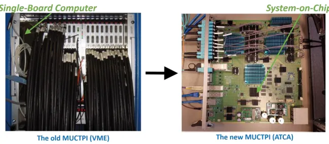
The upgrade of the MUCTPI to be installed for Run 3 is part of the overall upgrade of ATLAS on the road to High-Luminosity LHC [2]. The new MUCTPI will use optical links to replace bulky electrical cables. Those links will allow the muon trigger detectors to send more muon candidates with more precise information. The new module will provide improved overlap handling and full-precision information to the Topological Processor. It will be built as a single ATCA blade, see Figure 2. It will receive 208 optical links and will use two FPGAs for the overlap handling, counting of muon candidates, and sending candidates to the Topological Processor. A third FPGA will provide the total count of muon candidates to the CTP and read out data to the data acquisition system. A System-on-Chip (SoC) will provide hardware control of the new MUCTPI and integrate it into the ATLAS run control system.
Figure 2. The Upgrade of the MUCTPI from a VME-based crate to a single ATCA blade.
4 The ATLAS Run Control on a System-on-Chip
The run control system [3] of the ATLAS experiment provides a framework for the control of the MUCTPI, e.g. start and stop commands, loading of configuration data, e.g. overlap lookup table (LUT) data, and collection of monitoring data, e.g. counter values. Due to the new technology (ATCA) new ways of communication between the MUCTPI and the run control system had to be investigated. With the old MUCTPI that communication was achieved using a single-board computer. An SoC, Xilinx Zynq 7Z030 [4], with a programmable logic part and a processor part will be used for the communication with the run control system and the processing FPGAs of the MUCTPI, see Figure 3. The programmable logic provides the communication with the processing FPGAs using Chip-2-Chip links, the configuration of the FPGAs using the Slave Serial protocol, and the configuration and monitoring of the MUCTPI hardware with its power, clock and optical modules using serial buses like I2C and SPI. The processor system runs embedded Linux and an ATLAS run control application, which uses low-level user application software developed for the access of all the hardware and processing FPGAs of the MCTPI.
Figure 3. Run Control of the MUCTPI using a System-on-Chip, showing the place of the SoC as part of the hardware of the MUCTPI and as part of the the Run Control system of ATLAS.
4.1 Build Linux with Yocto
developed, in order to fetch, configure, and compile the software, and create all images necessary to boot and run the processor system.
4.2 Cross Compile Run Control
Yocto is used to provide a Software Development Kit (SDK), consisting of the cross compiler and all system libraries, see Figure 4. These are used together with a toolchain file for cross compilation with CMake [6] in order to build the ATLAS TDAQ software [7] including external software packages it depends on, e.g. the ROOT software [8]. The executables and libraries are installed in a directory which is mounted on the processor system using NFS.
Figure 4. Run Control Software Build Flow, showing Yocto for the build of the kernel and a root file system, and the cross-compilation of the TDAQ software.
4.3 Operate Run Control on the SoC
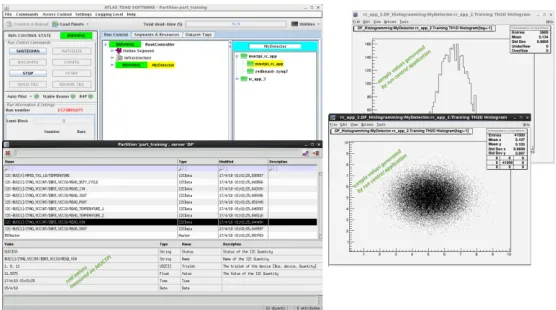
An ATLAS run control application runs on the SoC. It responds to state transition commands, receives configuration data, accesses the hardware of the MUCTPI, and produces monitoring information. The GUI to interact with this application is shown in Figure 5, including examples of ROOT histograms produced for monitoring.
Figure 5. ATLAS Run Control GUI and Monitoring Data from a standalone test of the MUCTPI, showing some run control windows and histograms from a dummy run control application.
5 Summary
developed, in order to fetch, configure, and compile the software, and create all images necessary to boot and run the processor system.
4.2 Cross Compile Run Control
Yocto is used to provide a Software Development Kit (SDK), consisting of the cross compiler and all system libraries, see Figure 4. These are used together with a toolchain file for cross compilation with CMake [6] in order to build the ATLAS TDAQ software [7] including external software packages it depends on, e.g. the ROOT software [8]. The executables and libraries are installed in a directory which is mounted on the processor system using NFS.
Figure 4. Run Control Software Build Flow, showing Yocto for the build of the kernel and a root file system, and the cross-compilation of the TDAQ software.
4.3 Operate Run Control on the SoC
An ATLAS run control application runs on the SoC. It responds to state transition commands, receives configuration data, accesses the hardware of the MUCTPI, and produces monitoring information. The GUI to interact with this application is shown in Figure 5, including examples of ROOT histograms produced for monitoring.
Figure 5. ATLAS Run Control GUI and Monitoring Data from a standalone test of the MUCTPI, showing some run control windows and histograms from a dummy run control application.
5 Summary
A System-on-Chip is successfully used to provide communication between the ATLAS run control system and the new MUCTPI. The Linux kernel and the root file system are built
using the Yocto framework. That framework had to be extended in order to compile the user application software for access of the MUCTPI hardware. Because building the ATLAS run control software also in the same framework proved to be impractical, the software development kit provided by Yocto was used together with a toolchain file to cross compile the ATLAS run control software in its own build environment. Finally, a run control application was developed which runs on the SoC, controls and configures the MUCTPI, and reads monitoring information, including ROOT histograms, from it. In the future it will be investigated if it is possible to improve the building and maintenance of the software further by making use of a common Linux distribution like CERN CentOS. But it has already been shown that a SoC can replace the single-board computers of the previous VME-based system in order to run a run control application on the new ATCA-based systems.
References
1. ATLAS Collaboration, JINST 3 S08003 (2008).
2. M. Silva Oliveira et al., Proc. TWEPP 2018 (in preparation).
3. ATLAS Collaboration, CERN/LHCC/2003-22 (2003).
4. Xilinx Inc., https://www.xilinx.com/products/silicon-devices/soc/zynq-7000.html.
5. The Yocto Project, https://www.yoctoproject.org.
6. The CMake Software, https://cmake.org.
7. ATLAS TDAQ Software, https://gitlab.cern.ch/atlas-tdaq-software.