Copyright to IJAREEIE www.ijareeie.com 10617
DOI: 10.15662/ijareeie.2014.0307048
Design and Implementation of PWM Stepper
Motor Control Based On 32 Bit Arm Cortex
Processor
Reenu George
1, Manoj G
2, S. Kanthalakshmi
3Assistant Professor, Department of Electrical and Electronics Engineering, Mar Athanasius College of Engineering,
Kothamangalam, India 1
Scientist, National Physical and Oceanographic Laboratory, DRDO, Kochi, India2
Associate Professor, Department of Instrumentation and Control Engineering, PSG College of Technology,
Coimbatore, Tamilnadu, India3
ABSTRACT:This paper describes the design and implementation of microstepper motor drive and a control system for two-phase hybrid stepper motor. Based on LM3S6965 arm processor, this paper proposes an approach to subdivide the step to microstep with required number of steps for stepper motor to improve positioning accuracy. Sine/cosine microstepping method is used to adjust the current in each winding of the stepper motor. This paper describes the running of motor at different speeds by changing the number of samples per rotation and position control by number of samples. The experiment showed that the system for controlling stepper motor can be used stably and reliably.
KEYWORDS:Stepper motor, microstepping, arm processor, control system, LM3S6965.
I.INTRODUCTION
Stepper motors are electromechanical devices that convert electrical pulses into discrete mechanical movements. Owing to their precision, robustness and reliability, they have a wide range of application in robotics and computer peripherals.The precision and performance criteria of stepper motors can be enhanced using segmentation technology [1]. In microstepping drive, one full step is broken into many discrete steps by continuously varying the current in the winding. The audible noise due to discontinuous stepping and resonance effect can be reduced by microstepping. Increase in rotor position resolution can be achieved by microstepping. All stepping modes are derived from the sinusoidal mode by adjusting the granularity of the driving sine wave [2]. Full step and half step consist of 90 degree and 45 degree of one sine wave period respectively. In microstepping, the motor basic steps (1.8 degree) are divided into number of steps by pulse width modulation (PWM) technique. Many microcontrollers can be used to control a stepper motor, such as 80C196MC, AT89C51, and PIC microcontrollers. However, depending on the complexity of the control algorithm (i.e., microstepper and current limiting), it can be advantageous to choose a microcontroller with selected peripherals that will take care of most of the stepper motors overhead [3]. The arm cortex processor provides a high performance, low-cost platform that meets the system requirements of minimal memory implementation, reduced pin count, and low power consumption, while delivering outstanding computational performance and exceptional
system response to interrupts. The LM3S6965arm processor is targeted for industrial applications, including remote
II.MICROSTEPPING DRIVE
Microstepping is a stepper motor technology that controls the current in the motor winding, where the number of steps can be increased by manipulating the current that the controller sends to the motor during each step and the resonance problem can be reduced using microstepping at a low step rate. Microstepping mode, which consists of sine and cosine wave forms, is used to drive the hybrid stepper motor instead of discrete pulses [5]. Sine and cosine equivalent pulse width modulation (PWM) pulses are generated using LM3S6965 to enable the drivers. In this scheme, sine cosine waves are applied to two-phase bipolar stepper motor windings. Sine/cosine waves are derived by varying the duty cycle in percentage of sine and cosine values. The pulse width of PWM pulses is proportional to the sine and cosine values. In the proposed scheme, sine values for 1440 samples with 0.25 degree increment is stored in an array and it is scaled by a factor of PWM period. These sine values are used to set the pulse width of the PWM signal. Four PWM signals of sine, inverted sine, cosine, and inverted cosine are generated with samples as follows
Sine sample=scaling factor*(1+sin (pi/180*degree)) (1)
Inverted Sine sample= scaling factor*(1-sin (pi/180*degree)) (2)
Cosine sample=scaling factor*(1+cos (pi/180*degree)) (3)
Inverted cosine sample= scaling factor*(1-cos (pi/180*degree)) (4)
PWM signals are inverted and through driver given to H-bridge, sine and inverted sine given to one arm of the motor and to other arm cosine and inverted cosine are given. Figure 1 shows generated PWM drive enable signal.
Copyright to IJAREEIE www.ijareeie.com 10619
III. HARDWARE DESIGN
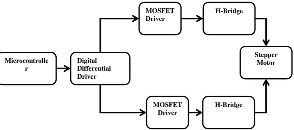
The block diagram of microstepper driver with LM3S6965 is shown in figure 2.
Fig 2. Block diagram of microstepper driver with LM3S6965
The LM3S6965 controller-based driver includes two phase bipolar stepper motor STP-MTR-23055(D), 26LS31 differential line driver, IR2110 MOSFET driver, and dual H-bridge. The PWM signals generated are complemented using 26LS31 quad high speed differential line driver. The control signals from differential line driver is fed to IR2110 high and low side MOSFET driver and IR2110 drives the power MOSFET to control the current in the winding. H-bridge circuit contains four MOSFET for each phase of the motor [6]. H-H-bridge is used for switching the current in the phase of the motor. The driver circuit for the stepper motor for one phase is shown in figure 3.
D4 BY V26E PH
D5 BY V26E PH
O/P PWM1 INV
U3 IR2110 LO 1 HO 7 HIN 10 SHDN 11 LIN 12 VSS 13 COM 2 VB 6 VCC 3 VDD 9 VS 5 O/P PWM1 AGND +15V C4 1uF D6 BY V26E PH C3 1uF +5V R3 10R R4 10R MOTOR PHA2 MOTOR PHA2 O/P PWM0
O/P PWM0 INV
U2 IR2110 LO 1 HO 7 HIN 10 SHDN 11 LIN 12 VSS 13 COM 2 VB 6 VCC 3 VDD 9 VS 5 AGND +5V +15V C2 1uF D3 BY V26E PH C1 1uF R1 10R R2 10R D S G Q1 IXFK48N/TO D S G Q2 IXFK48N/TO D S G Q3 IXFK48N/TO D S G Q4 IXFK48N/TO AGND +28V MOTOR PHA1 AGND C947uF D1 BY V26E PH
D2 BY V26E PH
Fig 3. Schematic diagram of full bridge driving circuit.
The experimental set up for driving the two-phase stepper motor using LM3S6965 is shown in figure 4.
Fig 4. Experimental set up
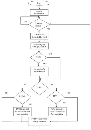
IV.POSITION AND SPEED CONTROL LOGIC
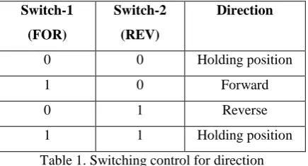
Stepper motor is controlled by PWM signal. PWM signal can drive the motor to rotate a fixed angle in accordance with the set direction and control the amount of angular displacement by controlling the number of pulses [7]. Number of rotations is proportional to the number of pulses and speed is proportional to the pulse frequency. In the proposed control scheme, three switches, one for speed control and two for direction control are used, which are read by the microcontroller. The forward and reverse directions are achieved by interchanging the PWM signals given to the phase. Constant PWM signal is given to hold the motor. Table 1 shows the switching control for direction.
Switch-1 (FOR)
Switch-2 (REV)
Direction
0 0 Holding position
1 0 Forward
0 1 Reverse
1 1 Holding position
Table 1. Switching control for direction
Different speeds are achieved by changing the pulse frequency. In the scheme, the speed is varied by the number of samples taken in one cycle to generate PWM signal. The larger the number of samples, the lesser will be the speed. Sample increment will be different for different speeds, which is controlled by the speed switch. Motor is rotated for a fixed number of rotations in both forward and reverse directions. The number of pulses for one rotation for different speeds is calculated using the following equation.
Number of pulses for one rotation = Basic steps per rotation /sample increment x 360 (5)
Copyright to IJAREEIE www.ijareeie.com 10621 Fig 5. Main program flowchart
V. CONCLUSION
REFERENCES
[1] S Rongrong and L Jing, “Stepper motor drive control based on MCU”, in Proc. IEEE International Conference on Control, Automation, and Systems Engineering (CASE), Singapore, 2011, pp.1-3.
[2] A Karthi, S R Paranjothi and S Solaimanohar S, “Implementation of digital micro-step driver for five-phase hybrid stepper motor using digital signal controller”, inProc. IEEE International Conference on Information, Communication and Embedded Systems (ICICES), Chennai, 2013, pp. 929-932.
[3] Z Wen, W Chen, Z Xu and Wang, J, “Analysis of two-phase stepper motor driver based on FPGA”, inProc. IEEE International Conference on Industrial Informatics, Singapore, 2006, pp. 821-826.
[4] A Bhargava and R S Ochawar, “Biometric access control implementation using 32 bit arm cortex processor”, in Proc IEEE International Conference on Electronic systems, Signal Processing and Computing Technologies (ICESC), Nagpur, 2014, pp. 40-46.
[5] S Angadi, V Saikumar and B Satyanarayana Kumari, “A novel digital controller for microstepping stepper motor drive using FPGA for solar array drive assembly in satellites – a comparison with alternative schemes”, in Proc. IEEE International Conference on Advances in Computing, Communications and Informatics (ICACCI), Mysore, 2013, pp. 1724-1729.
[6] N Greenough and C C Kung, “A new high efficiency stepper motor driver for old technology stepper motors”, in Proc. IEEE 25th Symposium on Fusion Engineering (SOFE), San Francisco, CA, 2013, pp. 1-4
[7] F Qi, X Jing, and S Zhao, “Design of stepping motor control system based on AT89C51 microcontroller”, International Conference on Advanced in Control Engineering and Information Science (CEIS 2011), China, 2011, pp. 2276-2280.
BIOGRAPHY
.
REENU GEORGE received B Tech in Electrical and Electronics Engineering from Kannur University in 2003. She joined as a lecturer in the Department of Electrical and Electronics Engineering, Mar Athanasius College of Engineering, Kothamangalam in 2005, where she is presently working as an assistant Professor. She has presented papers in national conferences. Her area of research includes stepper motor controls and microcontroller based applications
MANOJ G received M.Sc degree in Electronics from Kerala University Campus, Karyavattom in 2001. Subsequently, he worked as a Lecturer at an Engineering College. He joined DRDO as a Scientist on 2005 at Instruments Research and Development Establishment (IRDE), Dehradun. There he works in the field of Optical Design for various optical systems like Day vision system, Night Vision System, and Thermal imagers. He is currently working as a Scientist at Naval Physical and Oceanographic Laboratory (NPOL), Cochin. His current research interests include, design and development of Front end hardware and Telemetry development for Airborne Sonar, measurement systems – NACS, Stepper motor controls, audio cards and other microcontroller based designs like anemometer, SD card data logging, zigbee data communication, GSM data communication. He has published papers related to Challenges in Airborne Sonars, Sigma Delta Audio Cards, etc…