Implementation of Fragmentation of Long
Controller Area Network (Can) Messages
Utilizing CANTP
Sapna Shetty 1, Sriram K Kattimani 2, K.V.Prasad 3
PG Student [DEC], Dept. of ECE, Bangalore Institute of Technology, Bengaluru, Karnataka, India1
Senior Software Engineer, Robert Bosch Engineering and Business Solution, Bangalore, India2
Professor & Head, Dept. of ECE, Bangalore Institute of Technology, Bengaluru, Karnataka, India3
ABSTRACT: In this paper a productive CAN (Controller Area Network) diagnostic protocol is exhibited. The diagnostic choice assumes a critical part to recognize and find the reasons for disappointments. The "Information edge" of the CAN frame can bolster a size of 8 bytes which implies the transmitting hub can't transmit information over the measure of 8 bytes and getting hub can't get information over the extent of 8 bytes. This applies to application CAN messages, however the diagnostic messages/data can have a size of more than 8 bytes .The reason for this anticipate is to characterize a structure for the transmission of long information past the extent of 8 bytes in CAN organize. The convention utilized is CAN TP (CAN Transport Protocol).
KEYWORDS:AUTOSAR, CAN, CANTP, ECU, PDU
I
.
INTRODUCTIONThe present day vehicle relies upon many parts to work effectively. To hold those parts under the eye of a driver will make us feel more secure. In any case, by what method would we be able to screen these modules in the meantime as we drive in activity? As we as a whole know, all vehicles are outfitted with an instrument board which shows some data (turn on a red light, for instance) when something isn't right. That is vehicle diagnostic. With the assistance from inherent sensors, self-analysed ECUs and programming, the vehicle can screen its urgent capacities and demonstrate issues to the driver through the instrument board to stay away from threats. At the outset when everything was crisp it was challenging and fun undertaking to make those projects. In any case, as time cruises by, it feels that it is significant to accumulate them into one standard, both for better time and cost effectiveness and for less demanding adaption into future undertakings. Until today it is still so sloppy in the car world that each time another rendition of trucks turns out, the current system must be intensely changed or now and again new programming must be composed. Since there is no broad standard for the engineering, all the car fabricates are confronting bigger and bigger expense for their product improvement; and still, at the end of the day they are gambling more bugs in their new delivered vehicles. That is the explanation behind the makers to assemble and attempt to make another standard design, to abbreviate advancement time and lessen the expense in future.
Measured quality, adaptability, transferability and re-ease of use are the watchwords of AUTOSAR (Automotive Open System Architecture). These are made conceivable by characterizing a full capacity institutionalized interface for every module. By modularizing the product components, a producer can without much of a stretch pick the capacity modules as indicated by the necessity from the client: simply put the modules with the coveted capacities into the product and it is prepared to utilize, no compelling reason to stress how it will influence different parts of the framework.
With adaptability the blend of existing programming modules in various stages get to be conceivable on the grounds that AUTOSAR just characterizes the interface, the intricacy of the capacities is adaptable in light of the necessities of every vehicle sort. Transferability implies that you can put the module where it is required and where it will utilize the minimum framework assets. This will guarantee the improvement of asset utilization all through the vehicle.
Environment) to the equipment autonomous programming layer. So one producer can pick diverse suppliers for their ECU stages and they will even now participate as though they are made by one, along these lines minimizing the expense for programming.
In this paper, the technique to fragment long CAN messages utilizing CANTP compatible with AUTOSAR is displayed. The vehicle convention utilized here will be utilized to transport both diagnostic (e.g. OBD and UDS conventions) and AUTOSAR communication messages.
II
.
RELATEDWORKThe vehicles today have numerous parts which have to work effectively. Vehicle diagnostics is a very important feaure. Every time a new vehicle was introduced a lot of changes had to be done in the software of the vehicle which only added to the expense. Hence a standard design had to formed which is AUTOSAR (Automotive Open System Architecture) [1]. Every time there is a problem with the vehicle it gets stored as Diagnostic Trouble Code (DTC) in the PC memory. These DTC’s have to be read in order to identify the error in the vehicle system. CAN (Controller Area Network) protocol is used to read these DTCs . Each CAN frame has seven fields, which are Start of Frame, Arbitration Field, Control Field which comprises IDE (Identifier Extension) bit, reserved bits and the remaining four bits is the DLC (Data Length Code) , Data Field, CRC Field, Acknowledge Field and End of Frame. The CAN protocol supports Data Field of size 8 bytes[2]. DTCs are of size greater than 8 bytes. Hence the data has to be segmented to a size of 8 bytes to transport the data to the tester from the ECU (Electronics Controller Unit) as and when requested by the tester.
The transfer of data has to happen whenever the tester requests data that is the transfer is event triggered. The tester requests the data from the ECU by the using a service ID and the press of a button. Once the button is pressed the data is sent by the ECU based on the service ID[3]. CANoe is the tool best suited to view the data with regard to AUTOSAR. Flaws are physically designed and actuated at run-time utilizing a CANoe control-panel[4].
III. PROPOSED METHODOLOGY
Transport Protocol for CAN. CAN is a show, differential serial transport standard for interfacing ECUs (Electronic Control Units). In this system each hub (ECU) can get and send messages at various times. Every message frame contains a header (29 bits or 11 bits relying upon addressing format) and a message body (8 bytes). A message that is longer must be part into edges and for this situation timing between every framing is critical for the transmission to be effective.
A CAN diagnostic request produced in the application layer is sent through the DCM (Diagnose Communication Manager) and diverted by PDUR (Protocol Data Unit Router) to the CANTP module. CanTP is the module between the PDUR and the CAN Interface module as shown in Fig.1. The PDU Router conveys AUTOSAR COM (AUTOSAR Communication) and DCM PDUs onto diverse communication protocol. The routing through a system framework sort (e.g. CAN, LIN and FlexRay) relies on upon the PDU identifier. The PDU Router likewise figures out whether a vehicle protocol must be utilized or not. In conclusion, this module does gateway usefulness, when there is no rate change.
CAN Interface (CanIf) gives measure up to systems to get to a CAN bus channel paying little mind to its area (μC
inside/outer). From the area of CAN controllers (on chip/locally available), it extricates the ECU equipment format and the quantity of CAN drivers. Since CanTP just handles transport convention outlines (i.e. SF (Single Frame), FF (First Frame), CF (Consecutive Frame) and FC (Flow Control) PDUs), contingent upon the PDU ID, the CAN Interface needs to forward a PDU to CanTP or PduR. The main functions of CanTP are Segmentation of data, which do not fit into a single CAN frame, in transmit direction, Reassembling of data in receive direction, Control of data flow and Detection of errors in segmentation sessions. AUTOSAR CAN Transport Layer specification depends on the worldwide standard ISO 15765, which is the most utilized standard as a part of the automotive area.
CAN Interface (CanIf) provides equal mechanisms to access a CAN bus channel regardless of its location (μC
a single CAN frame, in transmit direction, reassembling of data in receive direction, control of data flow and detection of errors in fragmentation sessions.
Fig. 1.Position of CANTP in AUTOSAR
IV. IMPLEMENTATION
TABLE I.4 TYPES OF PROTOCOL DATA UNIT DEFINED BY ISO15765
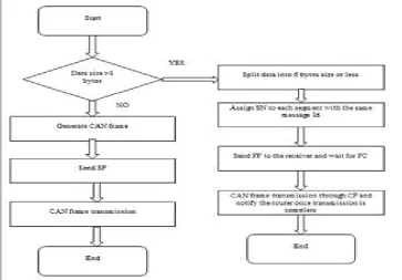
Fragmentation
CAN frame is a sort of short frame and bytes in its information field must be less or equivalent to 8, so four types of Network Protocol Data Unit (N_PDU) are characterized in the network layer protocol to transmit longer messages. Table 1 demonstrates the four sorts of N_PDU. Transmission of messages up to six information bytes is performed by means of transmission of Single Frame. Transmission of longer messages is performed by means of division of the message and transmissions of numerous N_PDUs which are First Frame and Consecutive Frames. N_Bs and N_Cr are the clocks that permit recognition of transmission errors. N_Bs implies time until gathering of the following Flow Control and N_Cr implies time until gathering of the following Consecutive Frame. Subsequent to sending the First Frame, N_Bs timeout clock, if ECU does not react before N_Bs lapses, error discovery will be shown to diagnostic instrument and all the left Consecutive Frames will be disposed of. The FS in the got Flow Control will choose how to continue the message transmission. On the off chance that FS=0, then Consecutive Frames are sent whose amount relies on upon the parameter BS, the transmission is halted when BS is reached and sit tight for another Flow Control; if FS=1, sit tight for another Flow Control and restart N_Bs clock; if FS=2, the transmission of divided message.
V. RESULTSANDANALYSIS
After developing the code the product is gathered and constructed utilizing SharCC tool. This code is then flashed on the ECU (Electronic Control Unit) utilizing Xflash instrument. TkWinx programming is utilized as the diagnostic instrument.
Fragmentation
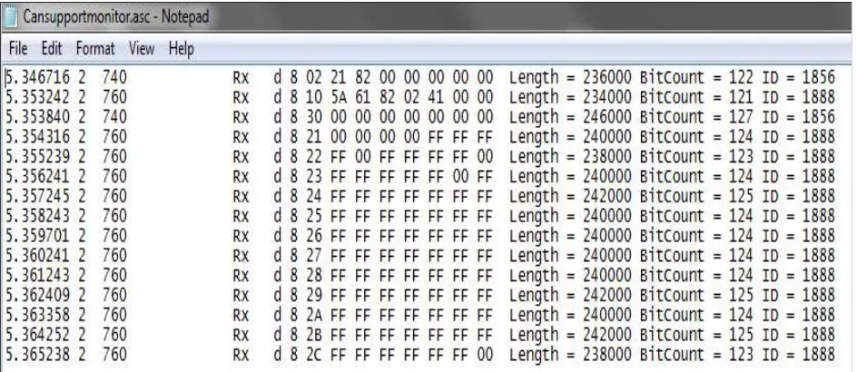
In Fig.3. Information size is more than 8 bytes. The service ID 21 82 is sent to ECU by tester whose ID is 740. This administration ID has a positive reaction hence 40 is added to the service ID and FF is sent to the tester by ECU whose ID is 760 alongside the data of aggregate number bytes to be transmitted. The sender then sends the FC to ECU and the ECU reacts with the CF. (compare with
TABLE I
)Fig. 3. Trace window when date size greater than 8 bytes is transmitted
Fig.4. For data measure lesser than or equivalent to 8 bytes the information is sent in the SF.
Fig. 4. Trace window when date size lesser than 8 bytes is transmitted
VI. CONCLUSION
ACKNOWLEDGEMENT
I express my gratitude to Dr.A.G.Nataraj, Principal of BIT, Bangalore for providing me an opportunity to take up this work. With immense pleasure I express my heartfelt thanks to my guide Dr.K.V.Prasad, Head of the Department, Dept of ECE, BIT, Bangalore for his motivation and valuable suggestions that helped in successful completion of this work. I extend my gratitude to Mr.Sriram K Kattimani, Senior Software Engineer, Robert Bosch Engineering and Business Solution, Bangalore for his timely support and help. Finally I am grateful to my family and friends for their encouragement during the course of my studies.
REFERENCES
[1] G. K. Hanssen, “A longitudinal case study of an emerging software ecosystem: Implications for practice and theory,” Journal of Systems and Software, vol. 85, no. 7, pp. 1455–1466, 2012.
[2] Hasnaoui, S. Kallel, O. Kbaier, R.Ahmed, S.B., "An implementation of a proposed modification of CAN protocol on CAN fieldbus controller component for supporting a dynamic priority policy", Industry Applications Conference, 2003. 38th IAS Annual Meeting. Conference, Vol 1, pp 23-3 1, Oct 2003
[3] Albert A. and Bosch R., "Comparison of Event-Triggered and TimeTriggered Concepts with Regard to Distributed Control Systems," Proceedings of Embedded World 2004, pp. 235-252.
[4] J. Arlat et al. Fault injection for dependability validation: A methodology and some applications. IEEE Transactions on Software Engineering, 16(2):166-182, Feb 1990.
[5] Leen and D. Heffernan, “Time-triggered controller area network”, COMPUTING & CONTROL ENGINEERING JOURNAL, DECEMBER 2001
[6] CAN Specification 2.0, Robert Bosch GmbH, 1991
[7] H. Jie, Y. Fuwu, T. Jing, W. Pan, C. Kai, “Developing PC-Based Automobile Diagnostic System Based on OBD System”, Power and Energy Engineering Conference (APPEEC), 2010 Asia-Pacific
[8] Chang-Min Shin, “Transmission method of long messages in CAN Network”, International Symposium on Embedded Technology, May 23-24, 2013.
[9] Fang Zhou, Shuqin Li, Xia Hou, “Development Method of Simulation and Test System forVehicle Body CAN Bus Based on CANoe”, Proceedings of the 7thWorld Congress on Intelligent Control and Automation, June 25 - 27, 2008, Chongqing, China.
[10] K.G. Shin, ªReal-Time Communications in a Computer-Controlled Workcell, º IEEE Trans. Robotics and Automation, vol. 7, no. 1, pp. 105-113, Feb. 1991.
[11] K.M. Zuberi and K.G. Shin, ªNon-Preemptive Scheduling of Messages on Controller Area Network for Real-Time Control Applications,º Proc. Real- Time Technology and Applications Symp., pp. 240-249, May 1995.
[12] K.M. Zuberi and K.G. Shin, ªScheduling Messages on Controller Area Network for Real-Time CIM Applications,º IEEE Trans. Robotics and Automation, vol. 13, no. 2, pp. 310-314, Apr. 1997.
BIOGRAPHY
1. Ms. Sapna Shetty is pursuing Masters Degree in Digital Electronics and Communication from Bangalore Institute of Technology, Bangalore.
2. Mr.Sriram K Kattimani is a Senior Software Engineer in Robert Bosch Engineering and Business Solution, Bangalore