Dynamic Shift to Reduce Test Data Volume in
Sequential Circuit Testing
Ancy Joy
1, Sani John
2Assistant Professor, Dept. of ECE, SCET, Trissur, Kerala, India1 Assistant Professor, Dept. of ECE, VJCET, Ernakulam, Kerala, India2
ABSTRACT:Testing of VLSI circuits are normally a tedious process due to the test data volume. It leads to extra power dissipation along with minimum fault coverage.This project presents a test data volume (TDV) reduction method for designs utilizing extremely high compression configurations, and it enables reducing the pin count interfacing with the Automatic Test Equipment. Based on the encoding requirements for every test cube, the proposed test compression method changes the number of shift cycles used to load the test stimuli dynamically. No additional pins or modification of the existing scan chains is needed, making the proposed method work with standard benchmark sequential circuits. A modification is proposed to reduce the test access time ,that is single cycle access with hold mode and single cycle access without hold mode. Instead of a long scan chain ,if each of the scan cells are tested separately in a single clock will reduce the access time and hence the effective testing time of sequential circuits.
KEYWORDS:Test Data Volume, Automatic Test Equipment , Single Cycle Access, Scan Chain, Testing Time
I. INTRODUCTION
Rapid advancement in very large scale integration (VLSI) technology has led to a new paradigm in designing integrated circuits, where a system-on-a-chip (SOC) is constructed based on predesigned and pre-verified cores such as CPUs, digital signal processors, and RAMs. Testing these cores requires a large amount of test data, which is continuously increasing with the rapid increase in the complexity of SOC. This has a direct impact on the total testing time and the memory requirements of the testing equipment. Hence, reducing the amount of test data is considered as one of the challenging problems in testing. As integrated circuit feature sizes continue to shrink, more functional blocks are integrated in a single chip. Meanwhile, complex fault models are often required to detect the defects resulting from the shrinking technologies and new manufacturing processes[1]. It in turn causes a dramatic increase of test data volume (TDV) and test application time (TAT).
As more and more devices are packed with in an integrated circuits(IC), complexity in physical design, fabrication and testing grows exponentially. Scan based testing is well known concept for its numerous advantages to implement with BIST logic. Test-per-scan (serial scan-in & scan-out) and test-per-clock (parallel scan-in & scan-out) are the two methods used in scan testing for better controllability and observability in the scan cells[4]. Power dissipation during testing is up to three times more than that of normal operation.
In this proposed system,the test compression method which changes the number of shift cycles dynamically to alleviate the low encoding capacity issue which may occur in high compression configurations. By changing the number of shift cycles dynamically per pattern, a different number of free variables can be supplied from the ATE to meet the encoding requirements from different test cubes such that it increases the encoding capacity as well as improves the encoding efficiency. Also the scan cells are modified as single cycle access with hold mode and without hold mode ,it may help to detect the faults in the flip flops with a clock cycle .Therefore it reduces the test access time.
II. LITERATURE SURVEY
.Therefore the difficulty of testing sequential circuits increases .Normally sequential circuits are converted to combinational mode and tested to obtain the fault coverage, Number of methods are used to test the sequential circuits. Time frame expansion method is based on fault-free/faulty-value justification. A synchronous sequential circuit can be represented as a linear iterative array of combinational cells. Each cell represents one time frame in which the current states of the flip-flops become pseudo-input (yi), and the next states become pseudo-outputs (Yi). So, we need to fault simulate the circuit under the given test set to determine faults detected. Improved scan design testing is the combination of LT-RTPG and 3 weight WRBIST.Test patterns generated by the LT-RTPG are selected and scanned into the scan chain to detect easy-to-detect faults and test patterns that are generated by the 3-weight WRBIST are selected to detect the faults that remain undetected after the first session. In Illinois scan chain architecture the scan-in pin that fed the original scan chain is routed to each of the scan chain segments. The segment scan-outs are routed to a multiple input signature register (MISR) as one might do in a logic BIST ed circuit. This option of course necessitates following most logic BIST design rules - e. g., avoiding unknown states, contending internal buses, setup/hold invalidated flip flop captures, or other BIST violations which could corrupt the signature(s).
III. OVER VIEW
A.
SEGMENTATION OF SCAN CHAINFor a test cube that is uncompressible when the number of channel inputs becomes small, there is no study to show which portion of specified bits in the test cube causes it to become uncompressible.After examining the locations of the specified bits for some uncompressible test cubes, observed that the uncompressible[2] specified bits come from the scan cells clustered in adjacent shift cycles. To verify this, divided the scan chains into multiple segments as shown in Fig.1. All the scan chains[3] in the design are left aligned along the scan chain inputs. Each column is called a scan slice. The adjacent scan slices are grouped into multiple segments with the same length starting from scan inputs to scan outputs. In Fig.1., two scan chains with different lengths are divided into three segments. That is, most segments included at least one specified bit.
Fig.1. Scan Chains With Three Segments
Then modified the linear equation solver to double the free variables used to solve the uncompressible segments while keeping the number of channel inputs as 2.
B.TEST APPLICATION WITH DYNAMIC SHIFT
When implementing a new test compression method, it is desirable not to modify the existing scan architecture. In order to allow changing the number of shift cycles dynamically without touching existing scan chains, the scan shift operation illustrated in Fig.2. is carried out as follows:
By halting SHIFT_CLK for N cycles and pulsing EDT_CLK continuously, more free variables are pumped into the decompressor. These free variables are used to encode the next scan slice and the scan slices thereafter.IfSHIFT_CLKis controlled directly from ATE, no additional hardware is required to support the scan shift operation shown in Fig 3. The additional cycles can be inserted before any shift cycles and the number of halting cycles, N, may vary in different shift cycles. If the shift clock is shared with EDT_CLK, SHIFT_CLK can be controlled by gating EDT_CLK through an additional control pin. This control pin is driven by ATE directly to disable SHIFT_CLK when it is necessary.
C.SEQUENTIAL CIRCUIT TESTING
Directly controlling the shift clock of a core from ATE may not always be feasible when embedding the core in SoC. Adding additional control pin per core is impractical in most of designs due to limited top level pins available for testing purpose. To avoid changing the interface between ATE and core inputs, add extra hardware in the decompressor to control the scan shift operations with additional cycles[8]. Fig.3. shows one of possible implementations without adding extra control pin.
In the implementation shown in Fig.3.divide the scan chains into S segments with equal length as shown in Fig.2. If the last segment, i.e., the one close to the scan outputs, is not long enough, additional shift cycles[6] are inserted to make it have the same length as other segments. During shift, each segment is controlled by the segment control data loaded into the segment control register and the size of this register is equal to S. When loading the control value 0 into the ith bit, no additional shift cycle is inserted in the ith segment. When loading the control value 1 into ith bit, N additional cycles will be inserted before every shift cycle in the ith segment. The scan chains are shifted by using the clock, INT_SHIFT_CLK, generated internally.
Fig.3. Dynamic Shift Controller
Although the dynamic shift increases the scan shift cycles by N times in the worst case, it increases the encoding capacity without adding channel inputs. By controlling the segments with shift cycles added as needed, it improves the encoding efficiency such that the test cubes could become compressible with a smaller number of channel inputs and more specified bits can be compressed
in each test cube.
The linear feedback shift registers can be used to generate the test patterns[7].IV. EXPERIMENTAL DETAILS
A. SINGLE CYCLE ACCESS STRUCTURE
B.SCAH-STRUCTURE WITH HOLD MODE
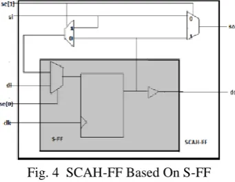
The key element of the single cycle access structure with hold mode (SCAhS) is the signal cycle access register(Flip-Flop, FF) with hold mode (SCAh-FF).
Fig. 4 SCAH-FF Based On S-FF
It is based on a standard scan register (S-FF) and uses two more 2-to-1multiplexers.The new SCAh-FF can be seen in fig 4. The SCAh-FF has one more input and one more output compared to the standard shift register (S-FF). The inputs clock {clk}, data-in {di}, and scan-in {si} still exists. The scan-enable is now a 2 bit bus {se[0:1]}. An additional scan output pin {so} is added.
V. RESULT AND DISCUSSION
The simulation results for the 8 bit universal shift register using dynamic shift scan chain is obtained as shown in fig 5.It is associated with two modes of operation. In normal mode ,that is when SE=0.When SE=1 the flip flops act as scan chain and it stores 1 bit in every clock cycle. These memory elements works along with the combinational circuits and behaves as sequential elements. It works based on clock cycles. When SE=1 the flip flops act as scan chain and they test all the memory elements along with the combinational circuit. In normal mode of operation the based on the modes such as 00,01,10,11 the universal shift register will do the operations no change, shift right, shift left and parallel input correspondingly.
Fig.5. Dynamic Shift Scan Chain in 8 bit Universal Shift Register
In Single Cycle Access with hold mode all the flip flops are tested simultaneously. Figure 4.9 shows the testing of 8 bit universal shift register using single cycle access with hold mode. The implementation results shows area consumption by the single cycle access with hold mode.
The additional flip flops will increase the area consumption. Since each of the scan flip flop has an additional two 2:1 multiplexers used to give the fault cover report in a single clock cycle itself. It ensures the hold mode of operation based on the select pin of the scan flip flop.
VI. CONCLUDING REMARKS
This paper presents a test data volume (TDV) reduction method to increase the encoding capacity and sequential circuits can be effectively tested to improve the fault coverage.A modification is proposed to reduce the test access time ,that is single cycle access with hold mode. Instead of a long scan chain ,if each of the scan cells are tested separately in a single clock will reduce the access time and hence the effective testing time of sequential circuits.If single cycle access with hold mode is used, with the addition of two 2:1 multiplexer in each scan cell ,at a single cycle itself any of the scan cell can be tested.
REFERENCES
[1] Nur A. Touba, “Survey of Test Vector Compression Techiques ,” in IEEE Design and Test of Comp, Jul.-Aug.,2006,pp. 294-303. [2] B.Koenemman ,”LFSR Coded Test Patterns For Scan Design, “ in Pro European Test Conf ., 1991 ,pp 237-247.
[3] I. Pomeranz and S. M. Reddy, “On reset based functional broadside tests,” in Proc. Design Autom. Test Euro. Conf., 2010, pp. 1438–1443. [4] F. Hsu, K. Butler , and J. Patel “A Case Study On The Implementation of the Illinois Scan Architecture, “ Proc. Intl.Test Conf., 2001, pp. 538-547.
[5] J. Rajski et al., “Embedded Deterministic Test,” in Trans. on CAD, vol. 23, May 2004, pp. 776-792.
[6] Polian and F. Fujiwara, “Functional constraints vs. test compression in scan-based delay testing,” in Proc. Design, Autom. Test Euro. Conf., 2006, pp. 1–6.
[7] B. Konemann, “LFSR-coded test patterns for scan designs,” in Proc. Euro. Test Conf., 1991, pp. 237–242..
[8] Xijiang Lin and Mark Kassab,” Using Dynamic Shift to Reduce Test Data Volume in High-Compression Designs” IEEE European Test Symposium (ETS), 2014.
BIOGRAPHY
Ancy Joy was born in India, on September 04, 1991. She graduated from Rajagiri school of engineering &technology,Cochin, Kerala, India in Electronics & Communication Engineering (2013). She completed Master of Technology in VLSI and Embedded Systems from Viswajyothi College of Engineering and Technology, Ernakulam, kerala, India. Currently she is working as assistant professor in Sahrdaya College of Engineering and Technology Trissur . Her special fields of interest include VLSI and Embedded System Design.
Sani John was born in Thodupuzha ,on 10th January 1985.she is graduated from University college of engineering MuttomThodupuzha Kerala in Electronics and Communication and took her M Tech in VLSI and Embedded System from Viswajyothi college of engineering and technology Vazhakkulam,Muvattupuzha. Currently she is working as assistant professor in viswajyothi college of engineering and technology Vazhakkulam . Her special fields of interest include Electronic Devices and Circuits and Image Processing.