Available Online atwww.ijcsmc.com
International Journal of Computer Science and Mobile Computing
A Monthly Journal of Computer Science and Information TechnologyISSN 2320–088X
IJCSMC, Vol. 3, Issue. 6, June 2014, pg.54 – 68
RESEARCH ARTICLE
Metadata-Based Modeling Approach: A
Multi-Viewpoints UML Profile
Ali Hassan Muosa
Department of Computer Science, Faculty Science Computers and Mathematic, Thi-Qar University, Iraq [email protected]
A
BSTRACTThese papers is a process associated with UML, which deals with structural aspects to use in methodical a
way, development process offers a complete multi-views modeling via dealing with both structural and
behavioral aspects. The achieved work saved all features of multi-views system (MVS) in metadata-based
model as matrix/cross-table does not set about the behavior aspects of the modeling process. The
metadata-based approach addresses a structural aspect related to the share of features’ views and to sharing data
without referring to the way these views will respond or how to be able to synchronize them in order to
obtain the behavior of multi-view objects (instances of a multi-view system). The achieved work in these
papers aims to fill this space by providing a new mechanism to the UML profile that allows expressing the
behavioral needs of a system. We will focus on describing the individual behavior of multi-view objects by
Actors-Views that require adjustments of UML modeling concepts.
Keywords: Multi-View Modeling, Metamodel, Viewpoint, Metadata, Actors-Views, UML Profile
1. I
NTRODUCTION
The concept of viewpoint also exists in the computer science world [1]. A system may be describing
according to several viewpoints [2]. A viewpoint allows to break up the system and to focus on a
particular aspect of the system, and introduces specific concepts which take into account the aspect
We present a proposal for Multi-viewpoints by using UML Profile. Currently in this work, we will
not focus on relations between classes diagram, but rather we describe the proposed profile
requirements, as the profile shall enable specifying, visualizing, and documenting the artifacts of
software system provided by UML to allow a smooth integration of existing tools that support UML.
In addition, the modular representation of metadata-based model (cross-table) to features’
permissions provides a complete set of Elements or Stereotypes model that enable representing the
semantics of the system based on Aspect-Orientation.
Our work has resulted in the definition of the multi-view modeling provides formalism and a
methodology to execute a metadata-based modeling approach from analysis to design. Therefore, we
must move all information about actor to the Actors-Views model and in the end; manage their
consistency by using Metadata-based model to save current and new information about this system
through collecting this information, which depended on current system (Real-World environment,
and actors) as Viewpoints “Metadata-based model matrix/cross-table”. Additionally, we should be
permission all features of actors in the cross-table. This critical decision may arrive to support more
consistency between views.
2. MULTI-VIEWPOINTS MODELING
Each class is statically multi-view construct of a metadata-based and an Actors-Views series
extending this basis [4]. A class can be customizing for views; the result is also
multi-viewpoint profiles, inheriting from the parent MVS. Every multi-represented or MVS can be used
through one or more of actors [5].
We support the identification of dependencies between the actor-view of a multi-view modeling
profile during the analysis/design phase through declarations of features (explained in UML
profiles). Now, we provide integrated platform consisting of several modules Figure 1. The used
framework is to model specification UML Class Diagram incorporating Actors' viewpoints.
The system specification is not static and may evolve in order to answer new requirements. Instead
of entirely designing again the system, the stakeholder takes old designs and makes modifications by
adding, removing, and modifying instances of concepts.
In MVS, the stakeholder has to manipulate other views. Each view can change according to the
concern considered by the views. The stakeholder must modify the other views if he changes one
stakeholder cannot know the elements of the other views that have a relation with the modified
elements and the management of adaptation will be impossible [6].
For designing evolutionary MVS, we propose a design framework, which used as follows:
Establishment of the given various system views. Each stakeholder designs his view according to the viewpoint concepts. In our solution, we consider a viewpoint as a metamodel that describes in MOF [7], the concepts and the associations, which exist between them. This implemented metamodel with an UML profile [8]. Each considered view as a package stereotyped by the considered concern. The constructed package is according to the UML profile.
Establishment of the links between the instances concepts, those are in different views. Once the different packages are designed, the stakeholder must import them in a single package.
This multi-viewpoints framework can be used to support the design of heterogeneous and MVS.
Figure 1, formed by a set of UML Profile for multi-viewpoints components that define how used the
UML in domain-specific issues.
Viewer: is used to define the actors of the specific system.
Actors-Metamodel Profile building: the current definition of profiles provides limits to what
a profile can do a profile cannot contain changes to an existing metamodel.
Apply profile: the extensions to UML are introduce which make the profile more suitable for
specification of communication systems.
UML C.D. Modeling elements: class diagrams are the basic building block used to define the
design of a system.
Multi-viewpoint C.D. Building: using to predefined (determined ahead of time) UML profile
tools in order to building the multi-viewpoint class diagram.
C.D. incorporating Actors' viewpoints: represent a viewpoints result of need actors. Message
exchange can be specified using class diagrams.
MVP Metadata-based model: the designer may perform changes in the views by modifying,
for example, one of their metamodel elements.
3. Formal Illustrative Case
The designer may perform changes in the views by modifying, for example, one of their features.
Since the described system as a set of Multi-Views, any action on a view might cause a similar or a
different action on other views.
The Figure 2 below shows MVS features can model structural and behavioral characteristics to
specific a given, while having the chance to redefine the characteristics of the one class on which it is
connected by the specific relation and having the same signature via attributes permissions but with
different implementations. On the other hand, views of multi-viewpoints can specialization a class to
When we applying the multi-viewpoints of class C through the actors (X, Y, and Z), to get specifics
viewpoints describe as follows: where
- C is a Class.
- X, Y, and Z are Actors.
- Cx is view of actor X on class C (Cx= C drive X).
- Cy is view of actor Y on class C (Cy= C drive Y).
- Cz is view of actor Z on class C (Cz= C drive Z).
If the actors (X, Y, and Z) using all features as are (without any derivation) in the class C. Hence,
the class C= Cx= Cy= Cz, which it is mean "having all", and is used in many relations to
identify multi-views objects that have a same structural of properties. Objects which may be
represented (or "embedded") differently, but it has a same essential structure often said to be
“identical until an isomorphism” [9].
If the all of actors (X, Y, and Z) are used some of features that existing in the class C. Hence,
- X [selected some features] = Cx → C ≠ Cx,
- Y [selected some features] = Cy → C ≠ Cy, - Z [selected some features] = Cz → C ≠ Cz.
- Then we get at finally C≠ Cx≠ Cy≠ Cz.
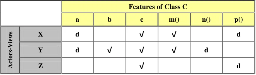
All these possible changes and their potential effects are summarizing in the Table 1. We have faces
is that correspondences may not provide all the information to implement that needed a change
required in other views by construct Metadata-based model as a cross-table of Viewpoints, when a
“Classes Features”. In general, correspondence rules express constraints that may help enforcing
changes to the related model elements.
Features of Class C
a b c m() n() p()
A
ct
ors
-V
iew
s X d
√
√
dY d
√
√
√
dZ
√
dTable 1: Construct Metadata-based model of Viewpoints associated to three Actors with one class.
In particular, the symbol:
'
√
': that is mean, the actor has shared may refer to this feature and also the approach starting from aformalization of the modifications is able to derive a set of models, which represents all the
possible consequences caused by these changes, and
'd': symbol that is meaning, class drive attribute/method, which we can represent by the other way
(i.e. ax, px, ay, ny, and pz), that mean identify that features for this class to avoid any conflict
between the classes, and we can say drive the attribute also (i.e. money attribute possibly used as
dollar/lira, etc…). Finally, we can get multi-view class diagram, as shown in Figure 3.
Each modification implies different kinds of adaptations over both the viewpoints and
Change identification: Changes in views and correspondences detected in order to identify the
elements involved. Existing model-difference techniques [10, 11] used to compare different
versions of views and correspondences; a proper difference model represents the outcome.
Change classification and cascading: The detected changes classified into the categories
moreover, the potential effects identified. For each modified element in a view, the set of
affected correspondences is identified first, and then the set of affected elements in other views
by navigating through the correspondences; these changes may trigger, in turn, further changes.
The process iterated until the sets of affected elements and correspondences are stable.
Change commitment and propagation: Starting from a marked model that identifies all
affected elements and possible changes the user asked to commit one by one the potential
changes. Once the user commits one particular change, the marked models with the affected
elements and changes recalculated, eliminating those alternatives ruled out by the user decision.
Please notice that committing a change may mean deciding how to implement it in the affected
correspondences and related elements,
The Actors-Views features to redefine the characteristics of the specific system that have some
classes on which the specific relation connects it and having the signature via attributes permissions,
but with different implementations Multi-Viewpoint can specialization a system.
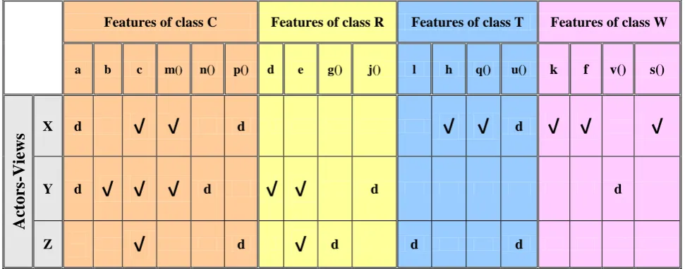
All these possible changes and their potential effects summarized in Table 2. A method of system for
preparing and modifying cross-tabulation analysis and reporting utilizes a data structure for storing
aggregate data, gathered or input from a stream of data records that represented system features.
Features of class C Features of class R Features of class T Features of class W
a b c m() n() p() d e g() j() l h q() u() k f v() s()
Ac
tor
s-Vie
ws
X d
√
√
d√
√
d√
√
√
Y d
√
√
√
d√
√
d dZ
√
d√
d d dIn the Table 2, Each row Actors-Views represented one actor viewpoint can be materializes as view.
However, we can add any new actors by create a new row and identify the features that is needed for
materialize as view.
So we can be summarized as the idea of this work by the possibility of modify the current
views/features as add new, remove, and modify; without the need to refer to redefine the rest of the
view that was not affected by this modification. Figure 4, which represented the MVS. Which
consists of three actors (X, Y, and Z) and four Classes are (C, R, T, and W).
It is a decentralized design phase, during which several teams designers can work separately to
achieve design templates for views. For each actor, we can develop apply the detailed class diagram for the viewpoint considered in gathering information deduced classes diagrams developed in Figure
4. The result is a set of models, each of which represents a specific viewpoint given. The class
diagrams according to the Figure 5 shows X Actor viewpoint; Figure 6 shows Y Actor viewpoint,
Observation: there are some problems that may happen when trying to maintain the synchronization
and consistency between views, once a change has happened (either in a feature of a view or in a
correspondence). However, before analyzing the problems, we need to be able to understand the
different kinds of changes, and the impact each one may have on the rest of the system
specification’s features. Thus, let us start by classifying the possible modifications occurring on the
features of views and correspondences as additive, subtractive, and updatetive.
More precisely, we will distinguish between three kinds of changes on view features:
Add features: introducing a new feature in a viewpoint is a common step in viewpoint
evolution. This type of change can imply that a correspondence between view features might
be add/modify in order to relate it to another view system.
Remove features: when removed a feature in a view, the correspondent feature in the views related might have removed; alternatively, the related correspondences may be
removed/modified.
Change features: modifying a feature may imply modifications on the related ones, or that
the corresponding possibly are changed/deleted.
Changes may also occur in any correspondence relating viewpoint specifications:
Add correspondence: adding a new correspondence may imply that a new feature must be
introduces or that a current feature must be update.
Remove correspondence: this may require that the related features should be modify/remove
Change correspondence: changing the specification of a correspondence may imply the
addition/modification of features in the views related by the correspondence.
All these possible changes and their potential effects summarized in Table 1. The first problem we
face is that correspondences may not provide all the information needed to implement the changes
required in other views by Construct Metadata-based model, when a change occurs in one view. In
general, correspondence rules express constraints that may help enforcing changes to the related
model elements.
4. Extending the M
2-Layer in UML Profile
In this work studded in metamodel in the M2-layer. Viewpoint metamodeling, whose result is a way
to make models of a specific kind, and we hope it can help us to more exactly what we can do in
addressing architectural representation specific purposes. Viewpoint modeling is not view-modeling
architects do those after a viewpoint has been defined?
Figure 8: Description for Metamodel for Extend.
This semantic Informal translated into rules of good modeling and present in Figure 8. The semantics
associated with informal elements of the metamodel is the UML follows:
The Class: is special class, metaclass element, which describes the structural characteristics and
behavior common to the actors in the system.
The Operations/Attributes: are structural model element and behavioral specific characteristics
target of one or more relationships actors.Classes define attributes, information that is pertinent to
their instances, and operations, functionality that the objects support.
Actors-Views: Materializes element a UML profile of actor Class. Such a view can be active.
Share element for modeling relationships between views. Each View may be associated with one
or more constraints that can be expressed in natural language, either in a formal language such as
OCL, database, and object oriented approaches.
Figure 9, gives an overview of the UML metamodel, the elements added to UML, entity marked in
dark color. We give here the semantics associated with informal UML.
Figure 9: Fragment of metamodel associated with the UML Profile.
A UML profile can be described simply as a set of elements added to the modeling UML metamodel.
However, add the notion of rule as advocated by SofTeam [12]. These rules can describe and
automation expertise on UML. In this way, UML profiles are a means effective to specify and guide
the development process UML.
During development at each stage, the profiles can express how to use UML what products are
expected development, and rules that the model must meet. By taking this approach, a UML profile
can be describe by:
Elements used UML (UML elements relevant to a given area),
UML extensions done (stereotypes, constraints, values marked),
The rules (the UML must display certain information and hide other), and
Transformation rules (rules and code generation patterns to assist or automate the development).
5. VALIDATION AND CRITICISM - CASE STUDY
The process in UML presenting the main steps. We stand as the case study we have adopted to
illustrate the contributions of this work. It is the management system of a vehicle repair agency. This
is a complex information system, involving several actors. For example, in Figure 10, the condition
of the Vehicle VehicleInReparation (Center of the Figure 10) is a multi-view approach, interpreted
differently by each actor type. A Mechanic concerned with breakdowns and repairs that must bring
the necessary tools to perform repair and spare parts. While one sees the WorkshopManager's side
Logistics is to say he likes assignments tracks, Book of equipment, assignment of spare parts, etc...
For a Customer, the technical details of repair are unimportant; it is more interested in the details of
the repair contract, by the expense and the date of completion of repairs. The interests of the
ChiefAgency focus on the financial aspect of this repair, including its actual cost, the estimated time
for completion of repairs and contract to establish with the Customer.
6. Actors Requirements Depiction
The management of vehicles: the system must be able to manage the vehicles within the
agency ensuring the following tasks:
registration of vehicles and customers,
operations management expertise and repair,
registration failures detected,
registration repairs,
test management failures repaired, and
saving the history of each vehicle (historical failures and repairs made).
Personnel Management: the system must manage the human resources agency, such as:
maintenances allocation to vehicles requiring expertise,
maintenances allocation to vehicles requiring repair, and
maintenances allocation to vehicles requiring a test.
Management of equipment: The system must manage hardware resources, such as:
assignment management of recovery vehicles,
assignment management tools,
management positions in the workshops (to obtain the appraisals, repairs and tests),
management of parking places, and
management of spare parts: assigning parts, signaling the exhaustion of the stock for a particular piece, order parts from the supplier, etc..
Manage of financial: the financial management tasks include:
Management contracts with clients,
Managing contracts with suppliers, and
Expenditure management's internal agency.
Each of these features is subdivide into functional units showing delicate responsibility assigned to
each actor. We limited the study to the following actors: the customer, ChiefAgency,
Figure 12:Use cases general application “Management agency repair of vehicles”, (VP-UML).
7. CONCLUSION
The main areas considered are: how to specify the views behaviors in order to meet the development
of UML approach, how to represent the interactions between viewpoints, how to construct
viewpoints of actors to represent the overall MVS behavior, and how we do ensure consistency and
integrity between these viewpoints. The generic component notion in multi-views modeling patterns
software, adapting current design patterns (single view) to support the development multi-views,
developing principles for the view features permissions of these patterns, and formalizing semantics
for these patterns.
To describe the construct views seen in the context of a MVS, two possibilities have been available
to us. The first has been to reuse mechanisms for specifying behavior and communication between
tools in UML. The approach based on the UML concepts, provides a method for describing and
coordinating separate features associated with objects and viewer. The main result is the
development of a data multi-viewpoints class, after UML specification, have role is to capture the
instances dynamic behavior considered MVS. Actors-Views represent the lifecycle of a
viewer-object while a Metadata-based model has been designed to create coherence and coordination
between features and specify the behavior common to actors.
The second is to finding a new mechanism adapted to extend UML. Therefore, we have chosen
specific modeling and Metadata-based model (matrix/cross-table) as an Actors-Views metamodel
element. We have introduced the sensor features concept specifying implicit communication actors
with MVS features, and transparent features observation.
BIBLIOGRAPHY
[1] Greenfield, “J. UML Profile For EJB”. Technical Report, Rational Software Corporation,
http://www.jcp.org/jsr/detail/26.jsp, Java Community Process (JCP), May 2001.
[2] J. Woch, “A UML Profile for Communicating Systems – Informal semantic Comparison and
Example”. Master thesis, Georg-August-Universitat, Gottingen, Germany, November 2006.
[3] A. Razavizadeh, S. Cîmpan, H. Verjus, “Multiple Viewpoints Architecture Extraction”. In:
Proceedings of the 2009 Joint Working IEEE/IFIP Conference on Software Architecture & European Conference on Software Architectures, p. 329–332, 2009.
[4] A. Razavizadeh, S. Cîmpan, H. Verjus, “Software System Understanding via Architectural Views
Extraction According to Multiple Viewpoints”. In: 8th International Workshop on System/Software Architectures, 2009.
[5] Barais, Olivier , Klein, Jacques , Baudry, Benoit , Jackson, Andrew, Clarke, and Siobhan,
“Composing Multi-View Aspect Models”. In seventh IEEE International Conference on Composition-Based Software Systems (ICCBSS), Madrid, Spain, February 2008.
[6] C.Chavez, C. Lucena, “A Metamodel for Oriented Modeling”. In Workshop on
Aspect-oriented Modeling with the UML, 1st Intl Conf. on Aspect-Oriented Software Development, Netherlands, 2002.
[7] OMG, “Object Management Group, Inc. Meta Object Facility (MOF) 2.0 Query/View/Transformation
(QVT) Specification”. version 1.0, April 2008.
[8] OMG, “Object Management Group, Inc. Unified Modeling Language (UML) 2.1.2 Superstructure”.
November 2007. available from: http://www.omg.org/uml.
[9] I. Abdelkader, “Advanced Modeling and Optimization”. Lecture Notes in Computer Science, Islamic
University of Lebanon, Beirut, 2010.
[10] A. Cicchetti, D. Di Ruscio, and A. Pierantonio, “A Metamodel Independent Approach to Difference
Representation”. In Journal of Object Technology, 6(9):165–185, October 2007.
[11] J. Rivera and A. Vallecillo, “Representing and operating with model differences”. In Proc. of TOOLS
Europe 2008, V, No. 11 of Lecture Notes in Business Information Processing, pages 141–160, Zurich, Switzerland, 2008.
[12] Softeam, “UML Profiles and Language J: Check the full application development with UML”. White
Paper, 1999. available from: http://www.softeam.com/ingenierie.php
[13] A. Anwar, “Formalizing a MDE approach the composition of models in the VUML profile”. PhD
thesis, University of Toulouse, December 2009.
[14] M. Nassar, “Analysis/design viewpoint: VUML Profile”. Thesis INPT, Toulouse, September 28,