Modeling and Weight Optimization of Oil Pan by Analysis
Kasala. Anil Kumar
& Virajee Reddy T
1
PG Student, Department of Mechanical Engg, Vidya Jyothi Institute of Technologyjntuh Hyderabad
2
assistant Professor, Department Of Mechanical Engg. Vidya Jyothi Institute Of Technologyjntuh,
Hyderabad
Abstract
In an internal combustion engine of the reciprocating
type the oil pan is the housing of the crankshaft. The
enclosure forms the largest cavity in the engine and
is located below the cylinder(s) which in a multi
cylinder engine are usually integrated in to one or
several cylinder blocks. Oil pan is located at the
bottom of engine. It is used to store the engine oil. Oil
will be pumped to the engine from the oil pan when
required. In this project modeling of oil pan used in
Submarine engine will be done. The aim of the
project is to model Oil pan using CAD software,
Initially data will be collected to design mould tool
and for the conditions of analysis. In next stage a
model will be generated using pro-engineer for
further study. Mould design calculations will be done
to model the mould assembly. After mould
preparation structural analysis will be conducted by
comparing the suitable material selection for oil pan
to optimize the die structure for weight reduction.
Modeling, will be done using catia v5software.
Keywords— Oil pan, Manufacturing Methods, Cost
Analysis, Design, Analysis
INTRODUCTION TO OIL-PAN
An oil pan is a component that typically seals the
bottom side of four-stroke, internal combustion
engines in automotive and other similar applications.
While it is known as an oil pan in the U.S., other
parts of the world may call it an oil sump. Its main
purpose is to form the bottommost part of the
crankcase and to contain the engine oil before and
after it has been circulated through the engine. When
an oil pan is removed, some components revealed
usually include the crankshaft, oil pickup, and the
bottom end of the dipstick. During normal engine
operation, an oil pump
will draw oil from the pan and circulate it through the
engine, where it is used to lubricate all the various
components. After the oil has passed through the
engine, it is allowed to return to the oil pan. In a wet
sump system like this, the amount of oil that an
engine can hold is directly related to the size of the
oil pan. An engine can hold no more oil than can fit
in the pan without reaching the crankshaft, since a
submerged crankshaft will tend to aerate the oil,
making it difficult or impossible for the oil pump to
circulate it through the engine. The drain plug used to
change the engine oil is typically located somewhere
on the oil pan. An easy way to locate an oil drain
plug is to find the pan and then look for its lowest
point. The pan may be slanted, have a bulge on one
end, or be at a slight angle due to the position of the
engine. This low point is usually where the drain plug
drained through it. Certain engines, such as those in
race or high performance cars, may make use of what
is known as a dry sump system. Instead of storing all
the oil in the crank case, these engines have a
divorced reservoir that it is pumped to and from. Oil
pans on engines like these will typically be much
smaller than those in wet sump systems, since the oil
is returned to the reservoir after being used for
lubrication.
Manufacturing Methods Of Oil-Pan General Capabilities:
1. Deep & Shallow Draw Stamping
2. Plastic Injection Molding
3. Rubber Injection Molding
4. Die-cast, Sand cast and Gravity Casting
5. Chrome and Vacuum Metallization
6. Extrusion and CNC machining
7. Wiring and electronic components
Oil pan specific capabilities: 1. OEM replacement oil pans
2. Fabrication ready oil pan cores
3. Custom oil pump pick-ups and dipsticks.
4. Wet sump fabricated to specifications
5. Dry sump fabricated to specifications
6. Fabrication components
7. Custom finishes
8. Highly customized work for volume customers
Manufacturing method is completely depends on
importance of the usage of component and engine
capacity and conditions In this project we are designing
OIL PAN for submarine engine
Methods Of Accumulating Costs In Records
Of Account
The balance sheet lists the components of inventory as raw
materials, work in process, and
finished goods. These accounts reflect the cost of unsold
production at various stages of completion.
The costs in work in process and finished goods are
accumulated or tabulated in the record of accounts
according to one of two methods: The Job-Order Cost
Method When orders are placed in the factory for specific
jobs or lots of product, which can be identified through all
manufacturing processes, a job cost system is appropriate.
This method has certain characteristics. A manufacturing
order often corresponds to a customer’s order, though
sometimes a manufacturing order may be for stock. The
customer’s order may be obtained on the basis of a bid
price computed from an estimated cost for the job. The
goods in each order are kept physically separate from those
of other jobs. The costs of a manufacturing order are
entered on a job cost sheet which shows the total cost of
the job upon completion of the order. This cost is
compared with the estimated cost and with the price which
the customer agreed to pay. The Process Cost Method
When production proceeds in a continuous low, when units
of product are not separately identifiable, and when there
are no specific jobs or lots of product, a process cost
system is appropriate, for it has certain characteristics:
work is ordered through the plant for a specific time period
until the raw materials on hand have all been processed or
until a specified quantity has been produced; goods are
sold from the stock of finished goods on hand since a
customer’s order is not separately processed in the factory;
the cost of production sheet is a record of the costs
incurred in operating the process or a series of processes
for a period of time. It shows the quantity produced in
is obtained by dividing the total costs of the period by the
total units produced. Performance is indicated by
comparing the quantity produced and the cost per unit of
the current period with similar figures of other periods or
with standard cost figures.
Elements Of Costs
The main items of costs shown on the income statement
are factory costs which include direct
materials, direct labor and factory overhead and selling and
administrative expenses. Materials The cost of materials
purchased is recorded from purchase invoices. When the
materials are used in the factory, an assumption must be
made as to cost flow, that is, whether to charge them to
operations at
average prices, at costs based on the first-in, first-out
method of costing, or at costs based on the last-in, first-out
method of costing. Each method will lead to a different
cost figure, depending on how prices change. Each
situation must be studied individually to determine which
practice will give a maximum of accuracy in cost figures
with a minimum of accounting and clerical effort. Once
the choice has been made, records must be set up to charge
materials to operations based on requisitions. Indirect
material
LITERATURE REVIEW
The first mathematical formulation of the FMS
loading problem was given by Stecke Grouping
and loading are formulated as non-linear 0-1 mixed
integer programs. Allocate the operations and
associated cutting tools of a selected set of part types
among the machine groups subject to the
technological and capacity constraints of the FMS
and according to some loading objective. These
problems are formulated in all detail as nonlinear
mixed integer programs (the nonlinear terms are
products of 0-1 integer variables).
Vidyarthi, at all proposed [3] a fuzzy-based
methodology to solve the machine- loading problem
in an FMS. The job-ordering determination before
loading is carried out by evaluating the membership
contribution of each job to its characteristics, such as
batch size, essential operation processing time, and
optional operation processing time. The operation–
machine allocation decisions are made based on the
evaluation of the membership contribution of an
operation– machine allocation vector.
Several heuristic solution based methods for the
machine loading have been developed. M. K.
Tiwari, at all [4] developed a heuristic solution
OIL-PAN & MODELLING
is a versatile process for producing engineered metal parts
by forcing molten metal under high pressure into reusable
steel molds. These molds, called dies, can be designed to
produce complex shapes with a high degree of accuracy
and repeatability. Parts can be sharply defined, with
smooth or textured surfaces, and are suitable for a wide
variety of attractive and serviceable finishes.
Die castings are among the highest volume,
mass-produced items manufactured by the metalworking
industry, and they can be found in thousands of consumer,
commercial and industrial products. Die cast parts are
important components of products ranging from
automobiles to toys. Parts can be as simple as a sink faucet
or as complex as a connector housing The Future
Refinements continue in both the alloys used in OIL-PAN
and the process itself, expanding OIL-PAN applications
into almost every known market. Once limited to simple
variety of sizes, shapes and wall thicknesses that are
strong, durable and dimensionally precise.
METHODS
OIL-PAN is a method of producing alloy castings by
injecting molten metal into metallic mold under pressure.
OIL-PAN process can be classified into
a) Hot Chamber Process
b) Cold Chamber Process
Material for `
The materials used for OIL-PAN are
1) Aluminum alloys
2) Zinc alloys
3) Magnesium alloys
4) Copper alloys
5) Lead alloys
Shrinkage Table for OIL-PAN alloys Table 3.2 injection pressure
Al/mg alloy Zn alloys Cu alloys Standard parts 400 100-200 300-400
Engineering parts 400-600 200-300 400-500
Pressure tight parts 800-1000 250-400 800-1000
OIL PAN DESIGN CALCULATIONS
(Mould setup calculations for tonnage with that only we can choose the plate size)
a = cavity area (top) = 6,39,037 mm2
a1 = cavity area (left) = 263346 x 2 = 5,26,692 mm2 a2 = cavity area (right) = 87785 x 2 = 1,75,570.4 mm2
v = volume of component = 90,56,532 mm3 Density of material (cast iron) = 7.81 g/cc
W= weight of the component = 9.050e-3 x 70.73 kgi = 70730 gm’s
L/t = 0 to 100(for mealy thick wall) 100 to 200 (most part’s)
200 to 300(thin walls)
300 and above (difficult to mould special equipment) Shot weight calculations
15% of component air flow = 10,609.5 gm’s 20% of component air flow = 14,146 gm’s Total shot weight:
Wt. of composite + wt. of over flow + wt. of runner 70730 + 10609.5 + 14146 = 95,485.5 = 95.5 kg’s 0.0602 min for material filling
0.5 min for cooling (coolant passage) 0.5 min for mould opening & closing Total = 1.0602 min
Therefore, 60 / 1.0602 = 56.59 56 comp/hr H-180Alxv = 180 ton
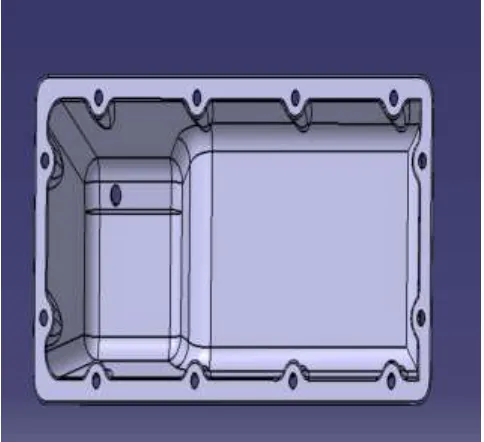
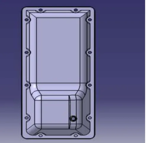
OIL PAN 3Design side view
OIL PAN 3Design back view
Table 4.4 aluminium (a360)
Density 2.68 g/cc
Tensile strength ultimate 317 MPa
Tensile strength yield 195 MPa
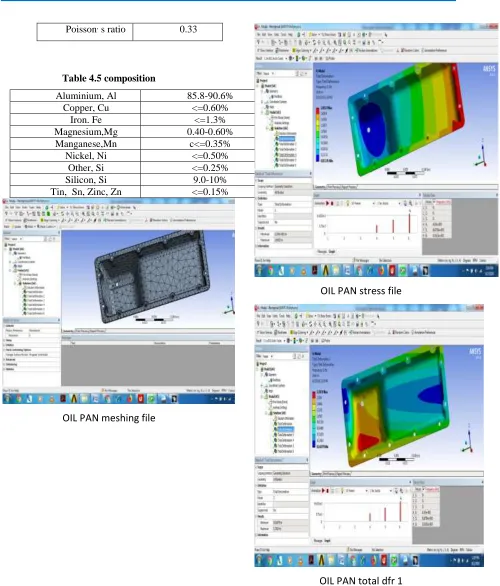
Poisson, s ratio 0.33
Table 4.5 composition
Aluminium, Al 85.8-90.6%
Copper, Cu <=0.60%
Iron. Fe <=1.3%
Magnesium,Mg 0.40-0.60%
Manganese,Mn c<=0.35%
Nickel, Ni <=0.50%
Other, Si <=0.25%
Silicon, Si 9.0-10%
Tin, Sn, Zinc, Zn <=0.15%
OIL PAN meshing file
OIL PAN stress file
OIL PAN total dfr
OIL PAN strain
OIL PAN total deformation
ANALYSIS RESULTS
Factor of safety for M.S. F26 is 200/91.486= 2.186
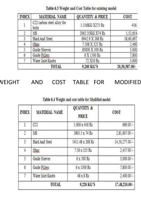
WEIGHTAND
COSTTABLEFOR
EXISTINGMODEL
WEIGHT
AND
COST TABLE FOR
MODIFIED
CONCLUSIONS
In this venture the enhancement of oil container
utilizing experimentation technique is finished. This
undertaking decreases the sum and time. In the initial
step the overview is led on oil skillet, its assembling
and cost estimation techniques. In the following stage
oil skillet demonstrate is readied utilizing expert/e
programming for assembling and cost estimation
reason. In the subsequent stage the form
computations are done and arranged shape apparatus
with existing and improved kick the bucket parts
models. In the subsequent stage basic investigation is
led on part utilizing customary material M.S F26 and
new material Aluminum A360 kick the bucket cast
compound. According to the examination results
Aluminum A360 is the correct decision to make the
oil container. As in the current form plan the hard
steel was utilized for the center and hole parts of the
bite the dust to withstand the high level of material
temperature at the purpose of liquid metal pouring to
such an extent this incorporates the material cost and
assembling time for the pass on to utilize the whole
strong square of center part with hard steel. So amid
the improvement and changes for this kick the bucket
shape it is chosen to part the center part into two
pieces like center embed and center plate. With the
end goal that center embed will be fabricate by hard
steel and the center plate will be produce by mellow
steel so it will diminish the material cost for the
center embed and the machining time required for it
and it will likewise facilitate the get together
technique. As though it is required to supplant the
center embed just in future. In this advancement just
the parts those are conveying a high material cost and
assembling time are streamlined yet other shape get
together parts are not adjusted as those are gathered
according to get together necessity. In this outline
enhancement and changes it is demonstrated that the
correlation for the assembling time required and the
material costs required when improvement and how it
will be valuable for the shape anufacturer from the
time and cost perspective. It tends to be presumed
that utilizing enhanced shape planning is more
preferences in cost astute and time compelling. By
utilizing improved form we can spare around 68 long
periods of machining time and almost Rs.3,00,000. In
Aluminum can lessen part cost almost 40%.
Aluminum A360 is likewise have the closest qualities
when contrasted with M.S. F26 so better to utilize
Aluminum rather than customary material so
organization can spare time and endeavors by doing
in chilly chamber heater rather than hot chamber.
REFERENCES
[1].
S. G. Ponnambalam and Low Seng
Kiat (2008) “Solving Machine Loading
Problem
in
Flexible
Manufacturing
Systems
Using
Particle
Swarm
Optimization” World Academy of Science,
Engineering and Technology 39
[2].
Sandhyarani
Biswas,
S.
S.
Mahapatra “Machine loading in Flexible
manufacturing
System:
A
swarm
optimization
approach”
Eighth
Int.
Conference
on
Opers.
&
Quant.
Management, 2007, NITR, 621-628
[3].
Kathryn E. Stecke, (1986), “A
hierarchical approach to solving machine
grouping and loading problems of FMS’S”,
European journal of operational research,
24, 369-378
[4].
M. K. Tiwari& N.K. Vidyarthi
(2000): Solving machine loading problems
in a flexible manufacturing system using a
genetic algorithm based heuristic approach,
International
Journal
of
Production
Research, 38:14, 3357- 3384
[5].
[11]
Paul
S.
Andrews,
An
Investigation into Mutation Operators for
Particle Swarm Optimization
[6].
[12] Akhilesh kumar, prakash, M K
Tiwari (2006), “Solving machine loading
problem of a FMS with constraint based
Genetic Algorithm”, European Journal of
Operational Research 175 (2006) 1043–
1069
[7].