Loaded with EBG Structures for High Gain-Bandwidth
Product Applications”
by Taha A. Elwi, Ahmed I. Imran, and Yahiea Alnaiemy, in Progress In
Electromagnetics Research C, Vol. 60, 157–167, 2015
Taha A. Elwi1, 2, 3, * and Ahmed I. Imran2
The third author, Yahiea Alnaiemy, was wrongly added and should be removed from this paper.
Received 7 June 2016, Added 13 June 2016
* Corresponding author: Giovanni Angiulli ([email protected]).
1 Department of Communication Engineering, Al-Mammon University Collage, Baghdad, Iraq. 2 Department of Electronics and
Communication, University of Baghdad, Baghdad, Iraq.3 Department of Physics, University Putra Malaysia UPM, Serdang 43400,
A Miniaturized Lotus Shaped Microstrip Antenna Loaded with EBG
Structures for High Gain-Bandwidth Product Applications
Taha A. Elwi1, 2, 3, *, Ahmed I. Imran2, and Yahiea Alnaiemy4
Abstract—In this paper, the design of a printed circuit antenna based on lotus flower patch of a miniaturized profile is proposed. The antenna consists of three layers including a patch and a ground plane of a thin copper layer separated by a Roger RT/duroidR5880 substrate for high gain-bandwidth product applications including microwave imaging systems. The patch structure is patterned with triangular defects to provide a fractal structure. Nevertheless, the ground plane is defected with Electromagnetic Band Gap (EBG) structures. The antenna is found to show a first resonant mode around 3 GHz, while the other frequency modes are obtained around 4.2 GHz and 6 GHz which are below −10 dB. Moreover, the antenna operates over the frequency range from 7.8 GHz up to 15 GHz with a bore-sight gain varing from 4 dBi up to 6 dBi when operates in free-space environments. The antenna size is reduced to a 32 mm×28 mm×0.5 mm using shorting plates on the substrate edges. The antenna performance characteristics are examined using CST and HFSS commercial software packages, which are based on the Finite Integration Technique (FIT) and the Finite Element Method (FEM), respectively. Finally, the antenna performance is tested experimentally for both S11 spectrum and radiation patterns to show an excellent matching with the obtained numerical results.
1. INTRODUCTION
The definition of ultra-wideband antennas by the U.S. Federal Communication [1] is to have a range from 3.1 up to 10.6 GHz bandwidth and satisfy the gain properties over the aimed frequency range. Printed circuit antennas show several advantages such as low profile, light weight and small size to make them excellent candidates for wideband applications. On top of that, the printed circuit antennas are suitable for integration with monolithic microwave integrated circuit (MMICs) that can be used in the biomedical devices. However, narrow impedance bandwidth is an inherent property of such conventional printed circuit antennas. Among several techniques that have been applied to enhance the microstrip antenna performance, coplanar transmission lines coupled to parasitic patches through gaps were suggested in [2–5] to increase the antenna bandwidth. However, the results from this technique showed that the antenna bandwidth cannot be enhanced more than few tens of a percent [6]. Other types of ultra-wideband microstrip antennas have been developed using different feed lines, such as microstrip line [7–9], coplanar waveguide (CPW) [10, 11].
The Zero Refractive Index (ZRI) structures have been used as perfect lenses firstly in the optical systems for zero focal point [12] and [13]. However, ZRI is realized lately to the microwave frequencies by scaling its dimensions toward practical wireless applications [14]. Currently, different categories of the ZRI structures are utilized in the antenna applications such as Electromagnetic Band Gap (EBG), Photonic Band Gap (PBG) structures and Frequency Selective Surface (FSS) [15–18]. The ZRI
Received 18 October 2015, Accepted 3 December 2015, Scheduled 21 December 2015
* Corresponding author: Taha A. Elwi ([email protected]).
structures suffer from several inherent limitations such as narrow bandwidth at which both permittivity and permeability simultaneously are near zero, high ohmic and radiation losses, and their profile is bulky and adds an extra dimension to the antenna structure [19]. These drawbacks take effects severely when the ZRI inclusions are embedded in the substrate of the microstrip antenna [19]. Nevertheless, the design complexity of the ZRI inclusions may be limited to the current production technology and fabrication cost [20, 21].
In this paper, an EBG structure is designed to enhance the gain of a wideband microstrip antenna with a miniaturized size. The design of the proposed antenna based EBG structure is mounted on a Roger RT/duroidR5880 glass microfiber substrate, with thickness = 0.5 mm, a dielectric constant
εr= 2.2 and loss tangent tanδ = 0.00134 for high gain-bandwidth applications. The antenna patch is shaped as a lotus flower loaded with fractal structures and the ground plane with square pads as EBG structures. The antenna shows an end-fire radiation pattern with boresight gain over certain frequency bands. The antenna dimensions are in length and width of 32 mm×28 mm.
2. DESIGN METHODOLOGY AND ANALYSIS
In order to realize the enhancements in the introduced microstrip antenna, the performance of the proposed EBG structure is identified in both analytical and numerical aspects. The electromagnetic properties of the proposed EBG structure can be investigated through evaluating the propagation constant and dispersion characteristics of a single unit cell structure.
2.1. The Design of the EBG Array and Art
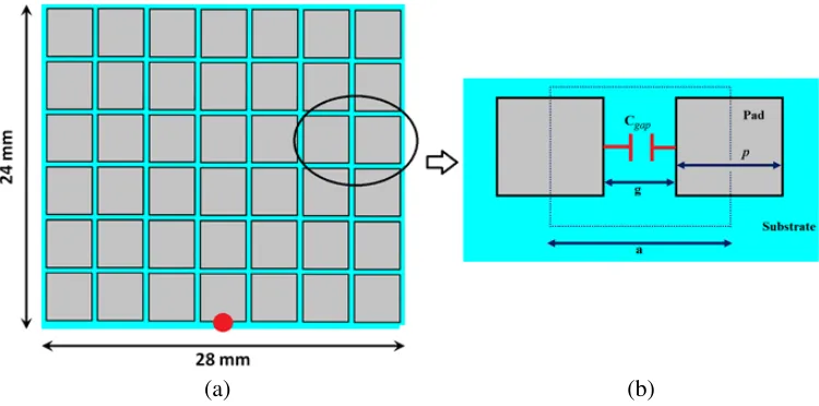
The proposed EBG structures are embedded in the ground plane for two purposes: Suppress the surface waves on the substrate and reduce the interference of the surface current on the ground plane. It is constructed of 6×7 array of square metal pads, to create 5×6 slots, and mounted on the back panel of the substrate, seen in Fig. 1(a). The dimensions of the proposed unit cell (see Fig. 1(b)) are 4 mm×4 mm. The EBG structure is based on a conductive square pad (p) of 3.6 mm×3.6 mm size spaced with a gap (g) 0.4 mm and mounted on the substrate.
(a) (b)
2.2. EBG Analysis and Performance Study
Such an array creates a capacitive gap (Cgap) between neighboring cells which can be calculated using the following formula [23] 1
C= pεo(1 +εr)
π cosh−1
p
+g
g
(1)
The proposed EBG structures exhibit a capacitive behavior [22], so work as a high-pass filter that allows passing the high frequencies and prevent lower bands. On the other hand, each unit cell can be considered unbalanced circuit because of the inductive absence where the influence of capacitive reactance on the EBG width is higher than its length for the surface current. Therefore, the reactance can be expressed by the following equation
Xc= 1 2πfcgap
(2)
wheref is the selected frequency.
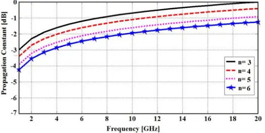
One of the main factors which control the proposed EBG performance is the number of slots (m×n) in their array. For this analysis, the number of slots along the length (m) is considered 5, and counting starts from the excitation location. Therefore, the number of slots along the width (n) is considered 3. Therefore, a parametric study is performed later to show the maximum propagation constant (γ) to be achieved versus frequency at different values of n. Fig. 2 shows the magnitude ofγ at n= 3 which can be evaluated from the following:
Zeq = Xc
n (3)
γ = R±jX (4)
|γ| = |Zeq| (5)
Now, a parametric study is presented with different numbers of slots in order to obtain maximum propagation constant (γ ≈ 1) by varying n as 3, 4, 5, and 6. It is worth to mention that the EBG slots repetition on the width influence has been selected depending on the size of the proposed EBG structure, the maximum size of the antenna, and the fabrication limitation. So, the capacitive reactance between unit cells on the width has high suppression for surface currents. The obtained results ofγ are depicted in Fig. 2. It is observed in all cases that when nincreases to above 3, γ decreases.
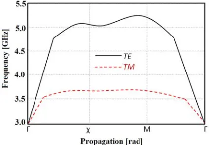
For an additional validation, the eigen mode simulation of the CST MWS formulations is invoked to localize the band-gap, natural resonances and dispersion properties, exhibited by the proposed EBG unit cell. The dispersion characteristics of TE and TM modes can be performed at the first Brillion Zone in the crystal lattice (Γ, χ,M) vertex. This is by considering a triangle of two equidistant sides (Γ to X and X to M), while the other longer side is (M to Γ). Each side can be described by the dispersion characteristics graph that can be merged in one continues dispersion diagram [24].
From the resulting dispersion diagram (see Fig. 3), the horizontal axis represents phase differences along the Brillouin Zone boundaries. However, it is seen in the frequency range of interest that the structure supports a fundamental TM mode whose electric filed is mostly longitudinal to the direction of the propagation, followed by TE mode which is predominantly transverse to the direction of propagation. Consequently, any propagation can be considered prohibited in TM mode under 3.5 GHz while in TE mode under 5.5 GHz.
Finally, a good agreement is achieved between the analytical results of γ and simulated results based on CST MWS formulations when compared at n= 3 and n= 5 as seen in Fig. 4.
Figure 3. Dispersion diagram of the proposed unit cell.
Figure 4. Comparison between the computed and simulated results for theγ.
3. ANTENNA DESIGN
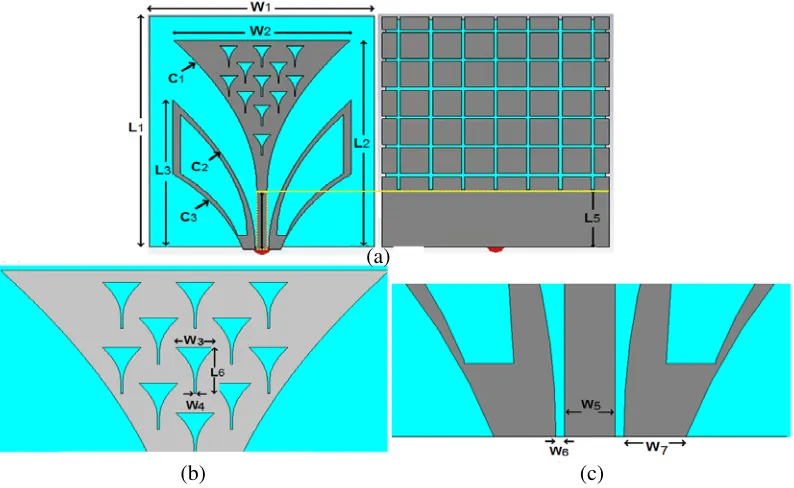
The antenna patch (see Fig. 5(a)) is shaped as a lotus flower and backed with the EBG array loaded to a rectangular ground plane. The patch structure is mounted on an RT/duroidR5880 substrate. The individual EBG unit cell on the ground plane is based on a square pad geometry to enhance the tangential component of the electric field and the broadness of the radiation toward the end fire. As depicted in Fig. 5(b), the patch is patterned with triangular fractal slots to increase the surface electrical area within the same physical area. To maximize the matching between the input impedance of the patch and the source over a wide range of frequencies, a flared coplanar transmission line is conducted from the source to the patch. The transmission line is excited by a 50 Ω port as shown in Fig. 5(c). The rest of the related geometrical dimensions of the proposed EBG unit cell and the ground plane are summarized in Table 1. The taper curve dimensions are expressed in [25, 26] as:
y =aeRx+b (6)
where, a and b are constants which can be described by the origin of the taper to the end of it with coordinates as (x1;y1) and (x2;y2), respectively. These constants can be determined as
a = y2−y1
eRx2 −eRx1 (7)
b = e Rx2y
1−eRx1y2
eRx2−eRx1 (8)
(a)
(b) (c)
Figure 5. The proposed antenna based EBG structures on the XY-plane: (a) front and back view, (b) enlarged view of the fractal slots and (c) coplanar transmission line view. Note: All the presented dimensions are in mm scale.
Table 1. The geometrical dimensions of the proposed antenna in mm.
Parameters Values Parameters Values
W1 28 W3 2
L1 32 W4 0.1
W2 21 L6 2.8
L2 28 W5 1.2
L3 20 W6 0.2
L5 8 W7 1.45
described by the following equations
C1 : y1 = 3.18eRx−11.56
W5
2 ≤x≤
W2
2 (9)
C2 : y2 = 3.06eRx−19.56
W5
2 +W6 ≤x≤
W2
2 (10)
C3 : y3 = 1.64eRx−18.52
W5
2 +W6+W7≤x≤
W2
2 (11)
where,R is the growth rate of the exponential of the taper and assumed to beR= 0.19. W2,W5,W6, and W7 are given in Table 1.
3.1. Antenna Design Methodology
The first antenna design is started from a solid triangular patch backed by a full ground plane to be denoted as case 1 as shown in Table 2. In addition, the S11 spectrum is evaluated by CST MWS. It is found that the full ground plane in case 1 provides narrow bandwidths around multiple frequency bands.
Next, the ground plane in case 1 is changed to a partial geometry, denoted as case 2, as seen in Table 2. As a result, the partial ground plane shows a wider bandwidth within frequency band with poor matching.
In case 3, a flared triangular patch geometry improves the impedance matching by adding two taper-shaped reflectors that act as matching circuits, and this addition reflects the radiation toward the end-fire direction as will be shown later in Table 2.
In the case 4, the EBG-defects are involved to the partial ground plane to improve the antenna matching. Excellent enhancements are found in the directivity, gain and beamwidth of the antenna due to suppressing the surface waves as will be explored later.
A further modification considered in this design is case 5 by including triangular patterns on the patch to create new resonance modes by increasing surface current paths on the patch. In addition, the internal areas of the coplanar transmission line reflectors are etched to improve the matching impedance of the antenna as shown in Table 2. Furthermore, removing the internal area of the coplanar transmission line reflectors insures the avoidance of any possibility of the coupling effects between the reflectors and the ground plane that may lead to a side radiation effects.
Finally, in case 6 the authors include shorting plates to the coplanar waveguide to work as matching circuits in addition to the size reduction. The antenna geometry and S11 spectrum are presented in Table 2.
From this comparison (see Table 2) the simulation results show that the antenna bandwidth, bellow
−10 dB, is enhanced in case 6 about 68.8% compared to the conventional antenna model in case 1. The enhancements in the antenna bandwidth are attributed to adding the partial ground plane and having the EBG structure effects as a high impedance structure discontinuing the surface current flow on the ground plane. The gain spectra are also affected with the change in the geometries of the ground plane and the patch. Generally, an excellent increase in the antenna gain of case 6 is found to be among other cases specifically from 6 GHz to 7 GHz as depicted in Fig. 6. Nevertheless, the average gain of the antenna denoted by case 6 is found to be changed between 4 dBi and 6 dBi.
Figure 6. Comparison of gain for all cases.
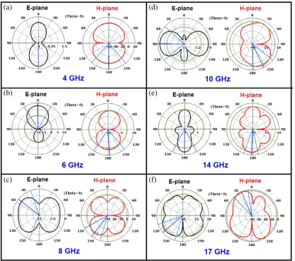
The radiation patterns of the antenna are illustrated in the E-plane (XZ-plane at Φ = 0) and
H-planes (YZ-plane at Φ = 90) as shown in Fig. 7. It is clearly seen that the radiation at 4 GHz is half wave dipole like whereas the antenna produces directional broadside pattern at 6 GHz. It can be noticed that the radiation pattern of the antenna design is toward the end-fire direction at 8 GHz to 10 GHz. This is accomplished by forcing the radiation to be directed along the end-fire by applying the flared reflectors. Nevertheless, the introduction of the EBG structure is to reduce the radiation leakage from the ground plane and providing more focusing toward the tangential radiation. However, the antenna shows broad side radiation at 14 GHz, and the radiation goes back to be end fire at 17 GHz.
(a)
(b)
(c)
(d)
(e)
(f)
Figure 7. Simulated radiation patterns in polar plot at different frequencies: (a) 4 GHz, (b) 6 GHz, (c) 8 GHz, (d) 10 GHz, (e) 14 GHz and (f) 17 GHz.
Figure 9. Effects of changing gap on the S11 spectra for case 6.
Figure 10. Effects of using different substrates on the S11 spectra.
directivity and reduce the side lobes without extending the antenna dimensions.
Next, a parametric study is applied to localize the best separation distance between the reflectors and the transmission line at which the matching can be maximized. The effects of separation distance on the S11spectra are monitored by changing it as 0.05 mm, 0.1 mm, and 0.15 mm as seen in Fig. 9. It is found that the coupling gap exhibits a significant effect on the magnitude of|S11|, bandwidth, and resonant frequency.
3.2. Effects of the Dielectric Constant Change of the Substrate on the Antenna Performance
This study is conducted to take consideration of the effect of substrate permittivity on antenna performance. From Fig. 10, it can be seen that the Roger RT 5880 with εr = 2.2 and tanδ = 0.00134 provides a wider bandwidth than other substrates with the same thickness. Therefore, under this condition, the Roger RT 5880 is used for the proposed antenna.
4. ANTENNA PERFORMANCE MEASUREMENTS
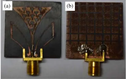
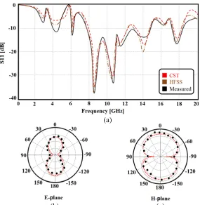
To verify performance of the proposed antenna design, a comparison of the performance of the fabricated prototype is applied against the simulated results. The fabricated prototype is depicted in Fig. 11. The performance of the implemented prototype is tested and measured then compared against the numerical simulations as seen in Fig. 12. The HFSS simulation is invoked as a further validation for the obtained results from the CST MWS before the antenna fabrication. The measured and numerical results are presented in terms of the S11 spectrum and the radiation patterns at 4 GHz only with a reasonable agreement as depicted in Fig. 12. In Figs. 12(b) and (c), the far-field radiation patterns of the fabricated prototype in theE- andH-planes are provided at 4 GHz with a gain of 5 dBi. The discrepancies between the measured and simulated S11 are attributed to manufacturing defects.
(a) (b)
(a)
(b) (c)
Figure 12. Comparison between measured and simulated results; (a)S11 spectra, (b)E-plane and (c)
H-plane.
5. CONCLUSION
The design of the miniaturized microstrip antenna based of a lotus flower profile is investigated in this paper. The patch geometry is etched with fractal triangular slots. Moreover, the patch structure is coupled to a flared coplanar transmission line to baked with a partial ground plane to increase the antenna bandwidth for wideband applications including the portable biomedical devices. The antenna operates over three individual separated bands around 3 GHz, 4.2 GHz and 6 GHz, and one continues band from 7.8 GHz to 15 GHz. The antenna bore-sight gain is found to be varied from 4 dBi to 6 dBi. The antenna is miniaturized to 32 mm×28 mm using shorting plates. Finally, the antenna performance is examined using CST and HFSS commercial software packages and compared against the experimental results for both S11 spectrum and radiation patterns to provide an excellent agreement.
REFERENCES
1. Federal Communications Commission, “First report and order, revision of Part 15 of Commission’s rule regarding ultra-wideband transmission system,” FCC 02-48, Washington, DC, Apr. 2002. 2. Wong, K. L.,Compact and Broadband Microstrip Antennas, John Wiley & Sons, 2002.
3. Wu, C. K. and K. L. Wong, “Broadband microstrip antenna with directly coupled and gap-coupled parasitic patches,” Microw. Opt. Technol. Lett., Vol. 22, No. 5, 348–349, Oct. 1999.
4. Huynh, T. and K. F. Lee, “Single-layer single-patch wideband microstrip antenna,”Electron. Lett., Vol. 31, No. 3, 1310–1311, Sep. 1995.
5. Wong, K. L. and W. H. Hsu, “A broadband rectangular patch antenna with a pair of wide slits,”
IEEE Trans. Antennas Propag., Vol. 49, 1345–1347, Jan. 2001.
7. Angelopoulos, E. S., A. Z. Anastopoulos, D. I. Kaklamani, A. A. Alexandridis, F. Lazarakis, and K. Dangakis, “Circular and elliptical CPW-fed slot and microstrip-fed antennas for ultrawideband applications,” IEEE Antennas Wirel. Propag. Lett., Vol. 5, 294–297, Jun. 2006.
8. Denidni, T. A. and M. A. Habib, “Broadband printed CPW-fed circular slot antenna,” Electron. Lett., Vol. 42, No. 3, 135–136, Dec. 2006.
9. Azenui, N. C. and H. Y. D. Yang, “A printed crescent patch antenna for ultrawideband applications,” IEEE Antennas Wirel. Propag. Lett., Vol. 6, 113–116, Apr. 2007.
10. Sudarsan, D., Y. K. Choukiker, S. K. Behera, and O. K. Kennedy, “Compact lotus shape planar microstrip antenna for UWB applications,” App. Electromagnetic Conf., 18–20, Dec. 2013.
11. Enoch, S., G. Tayeb, P. Sabouroux, N. Guerin, and P. Vincent, “A metamaterial for directive emission,”Physical Review Letters, Vol. 89, No. 21, 213902: 1–4, 2002.
12. Ziolkowski, R. W., “Propagation in and scattering from a matched metamaterial having a zero index of refraction,” Physical Review E Statistical, Nonlinear, and Soft Matter Physics, Vol. 70, No. 42, 046608-1, Oct. 2004.
13. Wu, Q., P. Pan, F. Y. Meng, L. W. Li, and J. Wu, “A novel flat lens horn antenna designed based on zero refraction principle of metamaterials,”Applied Physics A Materials Science and Processing, Vol. 87, No. 2, 151–156, Feb. 2007.
14. Xiao, Z. and H. Xu, “Low refractive metamaterials for gain enhancement of horn antenna,”Journal of Infrared Millimeter and Terahertz Waves, Vol. 30, 225–232, Jul. 2009
15. Kim, D. and J. Choi, “Analysis of antenna gain enhancement with a new planar metamaterial superstrate: An effective medium and a Fabry-Perot resonance approach,” Journal of Infrared Millimeter and Terahertz Waves, Vol. 31, No. 11, 1289–1303, Aug. 2010.
16. Hrabar, S., D. Bonefacic, and D. Muha, “ENZ-based shortened horn antenna: An experimental study,” Antennas and Propagation Society International Symposium, 1–4, San Diego, CA, United States, Apr. 2008.
17. Ju, J., D. Kim, W. J. Lee, and J. I. Choi, “Wideband high-gain antenna using metamaterial superstrate with the zero refractive index,”Microw. Opt. Technol. Lett., Vol. 51, No. 8, 1973–1976, Sep. 2009.
18. Pipes, L. A. and L. R. Harvill,Applied Mathematics for Engineers and Physicists, 3rd Dover Books on Mathematics, Jun. 2014.
19. Hou, Q. W., Y. Y. Su, and X. P. Zhao, “A high gain patch antenna based PN zero permeability metamaterial,” Microw. Opt. Technol. Lett., Vol. 56, No. 5, 1065–1069, May 2014.
20. Meng, F.-Y., Y.-L. Lyu, K. Zhang, Q. Wu, and J. L.-W. Li, “A detached zero index metamaterial lens for antenna gain enhancement,” Progress In Electromagnetics Research, Vol. 132, 463–478, 2012.
21. Ibrahim, O. A., T. A. Elwi, and N. E. Islam, “Gain enhancement of microstrip antennas using UC-PBG layer,” Canadian Journal on Electrical and Electronics Engineering, Vol. 3, No. 9, 480–483, ID: EEE-1211-016, Nov. 2012.
22. Elwi, T. A., Z. Abbas, M. A. Elwi, and M. M. Hamed, “On the performance of the 2D planar metamaterial structure,”International Journal of Electronics and Communications, Vol. 68, No. 9, 846–850, Sep. 2014.
23. Pipes, L. A. and L. R. Harvill,Applied Mathematics for Engineers and Physicists, 3rd Dover Books on Mathematics, 2014.
24. Elwi, T. A., “A further investigation on the performance of the broadside coupled rectangular split ring resonators,” Progress In Electromagnetics Research Letters, Vol. 34, 1–8, 2012.
25. Zhou, B., H. Li, X. Zou, and T.-J. Cui, “Broadband and high-gain planar vivaldi antennas based on inhomogeneous anisotropic zero-index metamaterials,” Progress In Electromagnetics Research, Vol. 120, 235–247, 2011.