1524 | P a g e
Design Optimization and Validation of the
Chassis of SUV car
Girish Punju Patil
1, Mr. Ashith Kumar Shetty
2,
Dr. Rajkumar E
31
School of Mechanical Engineering, VIT university vellore, (India)
2
Product Development Group, Altair Engineering Ltd, Bengluru, (India)
ABSTRACT
Automotive Chassis design is challenging task particularly in term of the weight reduction and simultaneously
consider all the vehicle loads and loads coming from the ground to make the chassis safe for real time
environment. In this paper, the chassis design from the dummy block using the topology, topography, size
optimization techniques is applied and that chassis model is tested virtually in Hypermesh (Opti strut) for
Durability Stiffness and Modal point of view. The desire dimensions of the chassis and loads applied
particularly for SUV cars. The objective of this study chassis weight reduction, fulfillment of the structural
performance for SUV cars.
Keywords: Automotive chassis design, Topology optimization, Topography optimization, Structural
Analysis, Modal Analysis.
I. INTRODUCTION AND LITURATUTRE SURVEY
Many Researchers published papers on the topology optimization related works. For the new product
development, there are series of challenges involved like designed product should sustain loads, occupy the
certain space only, material should be light weight, it’s cost should not be more than estimated cost. In such a
case, it’s difficult to predict which is the best and optimized design. Designer may know how the final product
look like but to get it design space needs the FE Topology optimization methods.
Now a days Researchers in the automotive industries are more focused on reducing the weight of the vehicle
because that directly improves the performance of the vehicle. Fuel consumptions, braking, Pollutant emissions,
Ride handling and performance is directly depending on the vehicle weight also. Topology optimization is
“Non-traditional” approach of achieving the targeted mass with best suitable mass distribution. Many paper
related to this work published. To cite few [1] address the optimization of the high-performance chassis design
with topology and topography approach. [2] discuss about the optimization through the series of constraints like
crash, modal, torsion and bending. Series of the manufacturing constraints and design constraints are defined to
achieve the final objective. [3] “address the optimization of the suspensions system” again with series of
bending and torsion and sway modes frequencies. [4] address the optimization of the air conditioning system
1525 | P a g e
constraints. [5] address the optimization under the minimum compliance under volume constraints for different
static loading. [6] gives the detail information on the topology optimization in hypermesh with Opti struct as a
user profile. Deck preparation was done in the hypermesh and Post processing in Opti struct and HyperView. [7]
address the extracting the chassis the light weight chassis through the topology optimization methods with the
stiffness, durability loads.
In this paper, the chassis model was extracted from the dummy block of the actual designed space for SUV cars
chassis. Extracted the chassis model through minimum compliance design under the durability loading and
Natural frequency loading constraints like Vertical bending, lateral bending and torsional Mode etc. Finally, the
optimized model was interpreted to construct the real time SUV chassis geometry in the Solid Thinking Inspire
2017.3.1 software. The Real-time geometry of the SUV cars which was constructed in Inspire ST was tested in
the same software for the Stiffness loads like Bending and torsion.
II.METHODOLOGY
2.1 Extracted the Solid Block out of the actual chassis Model or Actual design Space is consider for the
topology optimization.
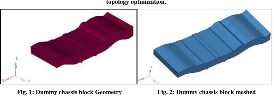
Fig. 1: Dummy chassis block Geometry Fig. 2: Dummy chassis block meshed
The dummy chassis block is model with Hexahedral elements as shown in Fig. 2 out of the geometry of the of
the solid block shown in Fig. 1. In the volume of the dummy block 311850 Hexahedral elements were created.
2.2 Rigids created at the locations were the loads applied and Durability loads were applied on the
independent node of those rigids.
Load Cases:
A] 321G_Front_Right _Side B] 321G_Rear_Left_Side C] 321G_Rear_Right _Side
D] 321G_Front_Left_Side E] 2G_Twist_Side F] 3G_Front_Side G] 3G_Rear_Side
Each load case includes around 30 loads. In that loads half were Forces and half Moments that to be applied on
the nodes in the model. Real times loads which the different chassis manufacturing industry uses for the testing
of their chassis were considered for the above deck preparation.
2.3 Initial material considered for the dummy block was STEEL AISI 304. Normal Deck without
1526 | P a g e
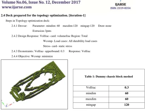
2.4 Deck prepared for the topology optimization. [iteration-1]
Steps in Topology optimization deck:
2.4.1 Desvar: Parameter- mindim: 60 maxdim:120 mingap:120 Draw-none
Extrusion-3pnts
2.4.2 Design Response: Volfrac- card: volumefrac Region: Total
Wcomp- Load cases: All durability load cases
Stress- card- static stress
2.4.3 Dconstraints: Volfrac- upperbound: 0.3 Response: Volfrac
2.4.4 Objective: Wcomp: minimize
Fig. 3: Optimization results of durability Aspects
In this iteration only the 30% of the actual volume is considered for the optimization. Fig.3 shows the topology
optimization results obtained in the above iteration.
Iteation-2:
In the Next iteration along with the durability loads the natural frequency aspect was also considered as the
constraints. Same as the previous iteration the in this also min 30% volume was taken for the optimization.
Normal chassis modes in frequency analysis:- Lateral Bending, Vertical Bending, Torsional Mode this modes
and their related frequencies were considered for the dconstraints and those frequencies were taken from the
baseline reference of the chassis.
2.4.5 Desvar: Extrusion-3pnts
2.4.6 Design Response: Volfrac- card: volumefrac Region: Total
Wcomp- Load cases: All durability load cases
Stress- card- static stress;
Lateral Bending : Vertical Bending : Torsional Mode
2.4.7 Dconstraints: Volfrac- upperbound: 0.3 Response: Volfrac
Lateral Bending : Vertical Bending : Torsional Mode
2.4.8 Objective: Wcomp: minimize
Table 1: Dummy chassis block meshed
Volfrac
0.3
mindim
60
maxdim
60
1527 | P a g e
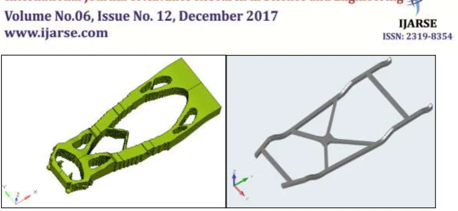
Fig. 4: Optimization results for Durability Fig. 5: Geometry constructed in the Solid thinking
and Modal aspects
The results obtained in the topology optimization in Opti struct was used to construct the geometry in Solid
thinking inspire 2.17.3.1. The outer structure and all beams are modelled according to the Fig.4 i.e optimized
results in the topology optimization. standard sections are considered in the geometry modelling in inspire.
2.5 ANALYSIS:
The Constructed Geometry in the solid thinking inspire was further tested for the Stiffness aspects.
Stiffness Aspects Considers Bending and Torsion.
2.5.1 Bending Analysis:
In the middle of the chassis the concentrated loads of the magnitude 750N was applied and the SPC
given at four different corners of the chassis.
1528 | P a g e
Fig. 7: Stress results in Bending Analysis
The displacements and stress results in the Fig. 6 & Fig.7 is well within the limit max. displacement is only
0.01137mm and max. stress is only 5.893Mpa respectively. Stresses in the model are well within the yield
strength of the Material.
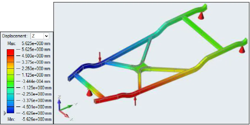
2.5.2 Torsion Analysis:
The loads appear in the deck are of magnitude 3296N each. The SPC are three at different locations as shown in
Fig. 8.
1529 | P a g e
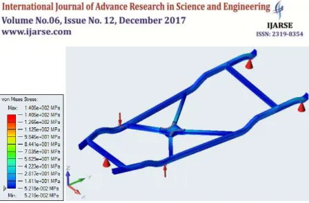
Fig. 9: Stress results in Torsion Analysis
Results in the above Fig. 8 and Fig. 9 shows the displacements and stress in the torsion analysis respectively.
Max. displacement in the torsion analysis is 5.624mmm only and von mises stress max is 140.6Mpa which is
within the yield limit of the steel (YS=210Gpa)
V. CONCLUSIONS
Topology optimization may be of single step optimization or multi step optimization. In this paper, the chassis
model is extracted from the single step optimization. It can be possible to go more in topology optimization for
refining optimized results. But in this paper, in first step only the results are interpreted for constructing the
geometry in the solid thinking and modelled geometry is further tested according to the different aspects or
different loading conditions.
VI. ACKNOWLEDGEMENTS
I wish to express my sincere gratitude to Mr. Rajesh Krishnan sir, director of enterprise solution group, for
providing me an opportunity to do my internship and project work in “Altair Engineering pvt ltd.”
I sincerely thanks to Mr. Vishal Nair, Sr. Technical specialist for their guidance and encouragement.
REFERENCES
[1]Marco Cavazzuti, Andrea Baldini, Enrico Bertocchi, Dario Costi, Enrico Torricelli, Patrizio Moruzzi.
High performance automotive chassis design:a topology optimization based approach, Structural and
1530 | P a g e
[2] J. Sobieszczanski-Sobieski, S. Kodiyalam, and R. Y. Yang. Optimization of a car body under constraints of
noise, vibration, and harshness (nvh), and crash. Structural and Multidisciplinary Optimization, 22:295–306,
2001.
[3] S. Kilian, U. Zander, and F. E. Talke. Suspension modeling and optimization using finite element analysis.
Tribology International, 36:317–324, 2003.
[4] J. W. Chang and Y. S. Lee. Topology optimization of compressor bracket. Journal of Mechanical Science
and Technology, 22:1668–1676, 2008.
[5] G. Chiandussi, I. Gaviglio, and A. Ibba. Topology optimisation of an automotive component without final
volume constraint specification. Advances in Engineering Software, 35:609–617, 2004.
[6] practical aspects of structural optimization Altair engineering ltd, 2nd Edition; Released 06/2015, Troy.