551 | P a g e
SLM AND SAVART PLATE BASED QUADRUPLE
MANCHESTER CODING AND DECODING
Animesh Bhattacharya
1, Amal K Ghosh
2andGoutam K Maity
31,2
Applied Electronics and Instrumentation Engineering Department,
3
Electronics and Communication Engineering Department,
1,2,3
Netaji Subhash Engineering College,
Techno City, Garia, Kolkata, (India)
ABSTRACT
With the demanding scenario of communication and computation technology the ternary and quadruple valued logic
systems are presently the most important ones in the multi valued logic system. Communication with huge of volume
data is an essential part in our daily life. The idea, knowledge or data that we have, is communicated over the world
using some techniques. The data that we communicate are in the form of bits .To make the transmitting data robust,
efficient and accurate we use some encoding/decoding techniques. One such most popular coding technique is the
‘Manchester coding’ which comes under the techniques of Digital Line Encoding and Decoding that are widely used in Industrial applications also. In this paper an optical quadruple Manchester encoder and decoder have been
implemented using exclusive-OR (XOR) and NOT logic gates based on Spatial Light Modulator (SLM) and Savart
Platein a simplified configuration. The performance ofthe circuit is evaluated through numerical simulation, which
confirms its feasibility in terms of the choice of the critical parameters. The proposed scheme has been
demonstrated for a Manchester encoder and decoder circuit using SLM and Savart Plate.
Keywords:Di-Bit, Manchester Encoderand Decoder, Quadruple, Savart Plate,SLM
I.INTRODUCTION
552 | P a g e operation but it was also felt that it is possible to implement multivalued logic in optical system using the polarization states of light beam along with the presence or absence of light [1]. SLM and Savart Plate can play a significant role in this field of ultrafast optical signal processing [2-3].This paper deals with the implementation of a Quadruple Manchester Encoder and Decodercircuit and explores the feasibility of the traditional quadruple Manchester encoder and decoder scheme in optical domain. This is studied thoroughly and confirmed through simulation results. The implementation can be scaled without the technical difficulties as is encountered in its electronics, due to the remarkable progress in photonics integration and the appealing characteristics of the SLM and Savart Plate. More specifically, this realization would develop ultra-high speed diagnostic and measurement equipment with comparative performance and cost advantages over their electronic counterparts.
This paper is organized as follows: The quadruple valued logic systemsare discussed in Section 2. Section 3 describes briefly the truth tables based on di-bit representation. Section 4 presents the working principle of basic building block using SLM and Savart Plate. Section 5 explains the working principle of a Quadruple Manchester encoder and decoder circuit using SLM and Savart Plate based exclusive-OR (XOR) and NOT logic gates. Section 6 presents logical simulation result by experiment. Finally concluding remarks are made in Section 7.
II.QUADRUPLE VALUED LOGIC SYSTEM
The four-state representations of the quadruple valued logic system may be classified as the true, partly true, partly false and the false [4-5]. In this case we have considered these four states explicitly as {0, 1, 2, 3} and their di-bit representations as {00, 01, 10, 11}. It is to be noted here that the four valued system with states {0, 1, 2, 3} does not satisfy the basic field conditions whereas as a di-bit representation of the form 00 0, 01 1, 10 2 and 11 3 may be used to represent a four valued logic where the basic two valued logic are applicable. As four is not a prime number, it can not be considered as a field nevertheless this can be included in Galois Field GF(kr), where k is a prime number and r is a positive integer . The logical states, their representations and corresponding di-bit representations and the state of polarization is given in the Table 1.
553 | P a g e
III.TRUTH TABLES BASED ON DI-BIT REPRESENTATION
The basic logical operations with dibit representation as mentioned in the earlier section may be expressed in the following fashion. In the present system the normal logical gates e.g., OR, AND, NOT, XOR, NAND, NOR and XNOR may be represented bit-wise. The truth table for these conventional bit wise logic gates are represented in Table 2.
Table 2. Truth tables for (a) OR, (b) AND, (c ) NOT (d) XOR, (e) NAND, (f) NOR and (g)
XNOR Gates.
IV.THE BASIC BUILDING BLOCK
The basic building block to implement the logical operations in quadruple valued logic system is shown in Fig. 1. Light from a laser source L after passing through the polarizer P is polarized at an angle 45o with respect to the two crystal axes and incident on the Savart Plate S1 as shown in Fig. 1. The light incident on S1 is splitted into two
orthogonal components and comes out of S1 with a spatial shift between them. The electrically addressable negative
SLMs - P1 and P2 are then used for the controlling of two components of inputs beam. The nature of the negative
SLM is such that it is transparent when there is no electric voltage applied on it and it becomes opaque when an electric voltage is applied on it. The property of positive SLM is just reverse. Hence the input may be considered as in the form of di-bit (two bits) representation. The outputs from SLM are finally combined by the Savart Plate S2.
554 | P a g e
Fig. 1TheBasic Building Block
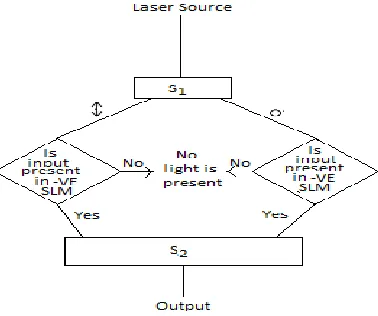
Fig. 2Flow Chart of Basic Building Block
V. PRINCIPLE AND DESIGN OF OPTICAL QUADRUPLE MANCHESTERENCODER AND
DECODER CIRCUITS
Manchester Coding is a popular technique which comes under the digital data coding. The term codingincludes both Encoding and Decoding. Purpose of an encoder is to convert the bits or data into a coded form and that of the decoder is to recover the original data from the coded form [6-9].A rise transition (Low to High transition) at the input side corresponds to a One („1‟) and a fall transition (High to Low transition) corresponds to a Zero („0‟). Because of the transitions at the mid of the bit, there is no chance of occurrence of DC signal, i.e. continuous zeros and ones.Quadruple Manchester coding and decoding table are given in Table 3. Here A(A1,A2) represents the input
data sequence, B(B1,B2) represents clock frequency, X(X1,X2) is the Manchester coded output and Y(Y1,Y2) is the
555 | P a g e
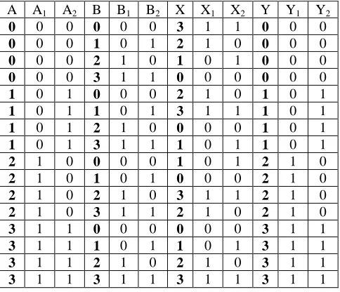
Table 3.Manchester Coding and Decoding Table
SLM and Savart Plate based quadruple opticalManchesterencoder and decoder circuit has been shown in Fig. 3.
The function s of SLM and Savart Plate are already explained in section 4.From Fig 3 it can be seen that the above figure consists of 4sections. 1st section and 3rd section perform the XOR operation whereas 2nd and 4th section perform NOT operation.1st and 2nd sections provide the coded output X (X1,X2) and 3rd and 4th sections provide
decoded output Y(Y1,Y2). The polarized parallel beam coming from the Laser source L through polarizer P is
incident on the beam splitter BS1 - where it is splitted into two directions as shown in Fig. 3. One part is incident on
the Savart Plate S1 and the other part on the beam splitter BS2. The Savart Plate S1 splits the beam into two
orthogonal components - the p-polarization (horizontal polarization) and the s-polarization (vertical polarization). The input A (combination of A1 and A2) controls the positive SLMs P1 and P2 and accordingly the p-polarization
and s-polarization come out of P1 and P2 and they recombined by the Savart Plate S2 and incident on the beam
splitter BS3. The output of S7 and S14 are combined by BS4 and acts as a control input for SLMs P13 and P14. The
output of S20 provides the Manchester coded output X (X1,X2). By the same procedure the output of S28 and S36 are
combined BS11 and acts as a control input for SLMs P29 and P30.
The output of S41 provides the decoded output Y(Y1,Y2). Some cases are explained as follows,
(1)When A=0 (A1=0,A2=0) and B=0 (B1=0,B2=0) then the output of S20 consists of both polarized light, hence X=3
(X1=1,X2=1). There will be no light at the output of S41, so the output is Y =0(Y1=0,Y2=0).
(2)When A=0 (A1=0,A2=0) and B=1 (B1=0,B2=1) then the output of S20 consists of only horizontally polarized light,
hence X=2 (X1=1,X2=0). There will be no light at the output of S41, so the output is Y =0(Y1=0,Y2=0).
(3) When A=0 (A1=0,A2=0) and B=2 (B1=1,B2=0) then the output of S20 consists of only vertically polarized light,
hence X=1 (X1=0,X2=1).There will be no light at the output of S41, so the output is Y =0(Y1=0,Y2=0).
A A1 A2 B B1 B2 X X1 X2 Y Y1 Y2
0 0 0 0 0 0 3 1 1 0 0 0
0 0 0 1 0 1 2 1 0 0 0 0
0 0 0 2 1 0 1 0 1 0 0 0
0 0 0 3 1 1 0 0 0 0 0 0
1 0 1 0 0 0 2 1 0 1 0 1
1 0 1 1 0 1 3 1 1 1 0 1
1 0 1 2 1 0 0 0 0 1 0 1
1 0 1 3 1 1 1 0 1 1 0 1
2 1 0 0 0 0 1 0 1 2 1 0
2 1 0 1 0 1 0 0 0 2 1 0
2 1 0 2 1 0 3 1 1 2 1 0
2 1 0 3 1 1 2 1 0 2 1 0
3 1 1 0 0 0 0 0 0 3 1 1
3 1 1 1 0 1 1 0 1 3 1 1
3 1 1 2 1 0 2 1 0 3 1 1
557 | P a g e (4) As A=0 (A1=0,A2=0) and B=3 (B1=1,B2=1) then there is no light at the output of S20 and S41, hence X=0
(X1=0,X2=0) and Y =0(Y1=0,Y2=0).
(5) When A=1 (A1=0,A2=1) and B=0 (B1=0,B2=0) then the output of S20 consists of only horizontally polarized
light, hence X=2 (X1=1,X2=0).The output of S41 consists of only vertically polarized light, so the output is Y
=1(Y1=0,Y2=1).
(6) When A=1 (A1=0,A2=1) and B=1 (B1=0,B2=1)then the output of S20 consists of both polarized light, hence X=3
(X1=1,X2=1).The output of S41 consists of only vertically polarizedlight, so the output is Y =1(Y1=0,Y2=1).
(7) When A=1 (A1=0,A2=1) and B=2 (B1=0,B2=1) then there is no light at the output of S20, hence X=0
(X1=0,X2=0). The output of S41 consists of only vertically polarizedlight, so the output is Y =1(Y1=0,Y2=1).
(8) When A=1 (A1=0,A2=1) and B=3 (B1=1,B2=1) then the output of S20 and S41 consist of only vertically polarized
light so the output X=1 (X1=0,X2=1) and Y =1(Y1=0,Y2=1).
(9) When A=2 (A1=1,A2=0) and B=0 (B1=0,B2=0) then the output of S20 consists of only vertically polarized light,
hence X=1 (X1=0,X2=1). The output of S41 consists of only horizontally polarized light, so the output is Y
=2(Y1=1,Y2=0).
(10) When A=2 (A1=1,A2=0) and B=1 (B1=0,B2=1) then there is no light at the output of S20, hence X=0
(X1=0,X2=0). The output of S41 consists of only horizontally polarized light, so the output is Y =2(Y1=1,Y2=0).
Similarly, the other cases can be explained satisfying the Table 3.
VI.PERFORMANCE EVOLUTION WITH LOGICAL SIMULATION
The logical simulation for Manchester coding and decoding has been shown in Fig.4. In the said figure (a), (b), (c) and (d) represents the clock frequency, the input data sequence, the Manchester coded output and decoded output respectively.
558 | P a g e
VII.CONCLUSION
In this paper, we propose a SLM and Savart Plate based quadruple Manchestercoding and decoding techniques. In this study, the constructions of an optical Manchester encoder and decoder circuit have been explained and presented. The proposed schemes are relied on discrete logic gates. The core building block for these modules is the SLM and Savart Plate. The technical importance for the critical parameters extracted from the simulation results indicates that the design can be used with more than adequate contrast ratio and in a practically feasible way. This affirms that Manchester code can be created in the optical domain in a straightforward style as its electronic counterpart, without complex adjustments in its standard constructional form. The intensity losses due to beamsplitter in interconnecting stages may not produce much trouble for the required optical bits at the output as the whole system is digital one and the output depends only on the presence or absence of light. These designs understanding is very predicting regarding the issues of versatility, re-configurability and compactness. These circuits can be implemented and applied for various usages for which Manchester codes are necessary.The purpose of this study is to explore the quadruple logic system in four-state implementation whichis possible to handle more and more information at a time.
REFERENCES
[1] A.W.Lohmann,“Polarization and opticallogic, ”Appl.Opt., 25, 1986,1594-1597.
[2] Amal K. Ghosh, P.PalChoudhury and A.Basuray, “Modified Trinary Optical Logic Gates and their Applications in Optical Computation”, presented in the Third International Conference on CISSE 2007, IEEE, University of Bridgeport, 3-12 December 2007 and published in the proceeding on Innovations and Advanced Techniques in Systems, Computing Sciences and Software, 2008, 87-92.
[3] Amal K. Ghosh, Animesh Bhattacharya, Moumita Raul and AmitabhaBasuray,“Trinary Arithmetic and Logic unit (TALU) using savart plate and spatial light modulator (SLM) suitable for optical computation in multivalued logic”, Optics & Laser Technology, 44(5), 2012, 1583-1592.
[4] Amal K. Ghosh, Animesh Bhattacharya, AmitabhaBasuray “Quadruple - Valued Logic System Using Savart Plate and Spatial Light Modulator (SLM) and It's Applications” Journal of Computational Electronics , 11(4), 2012, 405- 413.
[5] Animesh Bhattacharya, Amal K. Ghosh” Encoder, Decoder, Multiplexer and Demultiplexer in Quadruple-Valued Logic System Using Savart Plate and Spatial Light Modulator (SLM)”International Journal of Modern Trends in Engineering and Research (IJMTER), 02(08),2015, 31-43.
559 | P a g e [7] Yu-Cherng Hung, Min-Ming Kuo, Chiou-Kuo Tung, Shao-HuiShieh, “High speed CMOS Chip Design
forManchester and Miller Encoder”, 5th International Conference on Intelligent Information Hiding and MultimediaSignal Processing, 2009, 588-541.
[8] Hoke S. Johnson, Monte Sereno, “Method and Circuit for decoding a Manchester Code signal”, Patent 5, 023 891, 1991.