Abstract Transactions, SMiRT-22 San Francisco, California, August 18-23, 2013
Division 3
Structural Model Seismic Response Comparison for a Complex Nuclear
Structure
Greg S. Hardy 1, Ruben Soto2, Shi Lu3, and Robert Kassawara4
1Senior Principal, Simpson Gumpertz & Heger Inc., Newport Beach, CA ([email protected])
2Staff 1 Engineer, Structural Mechanics Group, Simpson Gumpertz & Heger Inc., Newport Beach, CA 3Staff Consultant, Structural Mechanics Group, Simpson Gumpertz & Heger Inc., Newport Beach, CA 4Senior Project Manager, Structural Reliability and Integrity, EPRI, Palo Alto, CA
Introduction
The current fleet of Nuclear Power Plants (NPPs) in the United States typically have stick models (also referred to as lumped mass models) to represent the safety-related structures, both for the original design basis and for subsequent beyond design basis efforts, such as for the Individual Plant Evaluation for External Events (IPEEE) program. New plant applications are typically requiring that more modern and sophisticated finite element models be used for structural and seismic design analyses of their safety-related structures. These different structure modeling approaches used for existing/new NPPs have resulted in the question as to whether the existing stick models are adequate for use in Seismic Probabilistic Risk Analysis (SPRA) and Seismic Margin Assessments (SMA). New SPRA and SMA studies are being conducted for use in risk-informed applications as well as to respond to the new seismic hazard characterizations having much more energy in the high frequency range of the spectrum than was previously predicted. As a result, a key industry need exists to understand whether there is a technical basis for requiring the generation of new finite element models for the existing fleet of plants in support of seismic margin studies and SPRAs, and potentially for any future design basis actions that could result from the post-Fukushima 50.54f generic letters from the Nuclear Regulatory Commission (NRC).
EPRI has planned a set of research tasks to address this question related to the structural model fidelity as it pertains to seismic response requirements. To address this topic in a generic manner, four separate seismic response characterization studies have been considered:
1. Complex structure on soil site 2. Complex structure on rock site
3. Compact axisymmetric structure on soil site 4. Compact axisymmetric structure on rock site
The first of these tasks (complex structure on soil site) was undertaken as part of an EPRI research project [1] and is the subject of this paper. The EPRI project consisted of the generation of both a Finite Element Model (FEM) and stick model fixed-base responses for a complex nuclear structure. It also includes the study of soil-structure interaction (SSI) effects associated with the complex structure being founded on a soil site. If the stick models can be shown to closely represent the seismic response from a complex finite element model as a result of this first study, then it may not be necessary to complete the additional three studies.
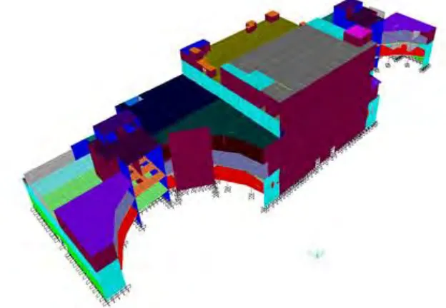
To support this EPRI research project, a Stick Model (SM) and a Detailed Finite Element Model (DFEM) were developed for the Control Building at the Vogtle Electric Generation Plant, Units 1 and 2. The control building represents a highly complex structure due to its non-symmetric nature, its large size, and the variety of load paths inherent in its design and configuration (Figure 1). A comparison study of the Vogtle control building SM and DFEM is performed to evaluate the effects of the inherent SM modeling simplifications based on the seismic responses to uniform hazard spectra (UHS) for the Vogtle site. The purpose of this EPRI study is to determine whether a SM is adequate to develop sufficiently accurate structural response of a complex asymmetric building on a soil site compared to a DFEM. Static 1g analysis results, modal properties, and in-structure response spectra (ISRS) are used to compare the similarities and differences between the two structural models. The fixed-base model comparisons are conducted to evaluate the differences between the two different structural models. The SSI analysis includes the dynamic effects of the site’s soil profile used to identify the contribution that soil has on the overall seismic response of the structure.
Results and Conclusions
Key results and conclusions from this research project revolved around the following areas:
Reasons for the natural frequency differences and significance assessments
Significance of stick model simplifications
Significance of input ground motion and corresponding spectral response shape
Differences in the seismic in-structure floor response
Recommendations for modeling considerations to ensure adequate response is generated from both DFEM and SM
Figure 1 – Control Building Finite Element Model
References
Structural Model Seismic Response
Comparison for Complex Nuclear
Structure
Simpson Gumpertz & Heger Inc.
Greg Hardy
Ruben Soto
Tim Lu
Electric Power Research Institute
Robert Kassawara
EPRI Research Project
Objective
-
Assess whether a LMSM provides adequate
seismic response characterization of a complex
asymmetric building compared to a DFEM
Electric Power Research Institute
(EPRI)
Dr. Robert Kassawara (EPRI Project Manager)
Principal Investigators:
Simpson Gumpertz & Heger Inc.
(SGH)
Greg Hardy, Shi Lu, Steve Short, David Nakaki, Ruben Soto, Kevin
Moore
Southern Nuclear Operating Company, Inc.
Bob Torkian, Robert Miller III, Don Moore
*EPRI Report to be published in Fall 2013
Driver for Study
Seismic Risk / Margin Assessments
Require “Adequate” Structure Models to
Develop Seismic Response
Post-Fukushima 50.54f seismic
recommendations
Risk-Informed Applications
Existing Nuclear Power Plants (NPPs)
typically only have lumped mass stick
models (LMSM)
Technical Adequacy of LMSM has been
debated in the industry for years
EPRI SPID developed some guidance for
EPRI Research Program on
Structure Models
EPRI has planned a set of research tasks to address
structural model fidelity as it pertains to seismic
response requirements
Four potential seismic response characterization
studies:
1.
Complex structure on soil site
2.
Complex structure on rock site
3.
Compact and/or axisymmetric structure on soil site
4.
Compact and/or axisymmetric structure on rock site
The first of these tasks is the subject of this paper and
consists of the generation of both the Finite Element
Model (FEM) and stick model responses for a complex
nuclear structure
Elements of the Study
Stick Model (LMSM) and a Detailed Finite
Element Model (DFEM) both developed
for Vogtle Control Building
Fixed-base and SSI responses studied
Comparisons made:
Static 1g analysis results
modal properties
Vogtle Control Building (CB)
Control Building supports both Units 1 and 2
6-story R/C shear wall structure w/ R/C slabs on steel
beams, and girders
Floor-to-Floor Height ≈ 20 ft
Height = 121 ft (bottom of basemat to roof)
Embedded (47 ft) on 3 sides
Basemat dimensions 525 ft x 169 ft
Complexities
CB has non-compact, irregular geometry
Irregularity in stiffness (tower to basement floors)
Torsional effects – 3 sides of shear walls and open
south side
22nd International Conference on Structural Mechanics in Reactor Technology
Plan View
Section
Lumped Mass Stick Model (LMSM)
Southern Nuclear Company regenerated
CB LMSM from 1983 design basis model
using SAP2000
Detailed LMSM with multiple sticks
Basemat treated as a rigid foundation
Uncracked sections
Lumped Mass Stick Model
Vertical elements represents a R/C wall
(red)
Horizontal elements are high stiffness frames
linking mass to R/C wall elements
(black)
Detailed Finite Element Model
(DFEM)
SGH developed DFEM from construction drawings
supplemented by 1984 Bechtel Model
R/C shear walls and slabs modeled w/ SAP2000
thick shell elements
Basemat treated as a rigid foundation
Uncracked sections
Finite Element Model
(structure only, w/o foundation)
~18,000 nodes
Detailed Finite Element Model
(DFEM)
Vogtle Control Building Model
Static Response of Structure
1g Comparison
Fixed-base DFEM and LMSM to 1g (X,Y,Z)
Satisfactory Mass comparison (<5%)
Mass comparison per Elevation below
Elevation
(ft)
Mass-DFEM
(Kip-sec2/ft
Mass-LMSM
(Kip-sec2/ft)
% Delta
Static 1g Comparison
180 200 220 240 260 280 300 3200 0.05 0.1 0.15 0.2 0.25 0.3
Elev
atio
n
(f
t)
1gX - Displacement (in)
DFEM - Tower NorthEast Corner
DFEM - Tower SouthEast Corner
DFEM - Center of Tower (C11/CD)
LMSM-at Mass
Y (North)
X (East) Z (Up)
Static 1g Comparison
180 200 220 240 260 280 300 3200 0.05 0.1 0.15 0.2 0.25 0.3 0.35 0.4
Elev
atio
n
(f
t)
DFEM - Tower SouthWest Corner
DFEM - Tower SouthEast Corner
DFEM - Center of Tower (C11/CD)
LMSM-at Mass
Y (North)
Modal Property Comparison
Frequency
(Hz)
X (%)
Y (%)
Z (%)
Dominant
Modes
LMSM DFEM LMSM DFEM LMSM DFEM LMSM DFEM
7.24
6.18
72
54
1
stY
7.66
6.73
64
45
1
stX
17.58
10.62
41
12
Vertical
Modal Property Comparison
0% 25% 50% 75% 100%0 10 20 30 40 50 60 70 80 90 100
Cu m u la ti ve M od al M ass P ar ti ci p ati on (%) Frequency (Hz) 0% 25% 50% 75% 100%
0 10 20 30 40 50 60 70 80 90 100
Investigation for Stiffness
Differences
Sensitivity Study on Diaphragm Flexibility
Assumptions
In-Plane Rigidity
Out-of-Plane Rigidity
Changed DFEM to Approximate the Diaphragm
Assumptions in the Stick Model
Assess the impact of the changes in the DFEM
Results show much closer correlation with the Stick
model
Thus, indication of some key differences in modeling
Modal Property Sensitivity
Plan View at Elevation 240 ft
• Unconstrained DFEM
Deformed Shape for the
First Y-mode
Modal Property Sensitivity
Plan View at Elevation 240ft
Elevation at Gridline 14 (east tower wall)
In-plane constrained DFEM
Deformed Shape for the
First Y-mode
7.5 Hz, 63% Y-MPR
Compared to LMSM, 7.2 Hz,
72% Y-MPR
Input Ground Motion
Vogtle Uniform Hazard
Spectra used for both
structural models
Time history and
strain-compatible soil properties
from seismic hazard
assessment
Site-specific in-column
response spectra at the
foundation for best
estimate soil stiffness
case
Results in peak / valley
Fixed-Base Analysis Comparison
Elevation 240 ft
DFEM
LMSM
Fixed-Base Comparison
Observations
Close comparison between the two fixed-base models was achieved
at some locations but not all locations
The LMSM’s use of rigid slabs resulted in an increased stiffness
in all three directions
The LMSM is unable to capture local modes at some locations
due to the lumping of masses at each floor level, which includes
out-of-plane slab modes
The discrepancies in the spectral accelerations directly related to
the differences in fundamental frequencies (sharp peak / valleys
augment differences)
In general, the fixed-base ISRS in the LMSM envelop the
SSI Comparison
5% damped
Foundation Response
Spectra,
DFEM
LMSM
Input Response
Spectra Purple
SSI Comparison – Examples of
DFEM >
LMSM
SSI Comparison – Examples of
DFEM >
LMSM
Y
(
N
or
th
)
X
(
Ea
st
)
Z
(
Up
)
SSI Analysis X, Y, & Z ISRS (left) at El. 220 ft, and Corresponding Plan View of El. 220 ft w/ location of ISRS
(right) 3-236E-i