TELEVIDEO@ SYSTEMS, INC. TS 800 USER'S MANUAL
TeleVideo Part Number 2252800 Rev. A 1 November 1983
Copyright (c) 1983 by TeleVideo Systems, Inc. All rights reserved. No part of this publication may be reproduced, transmitted, transcribed, stored in a retrieval system, or
translated into any language or computer language, in any form or by any means, electronic, mechanical, magnetic, optical,
chemical, manual, or otherwise, without the prior written permission of TeleVideo Systems, Inc., 1170 Morse Avenue, Sunnyvale, California 94086.
Disclaimer
TeleVideo Systems, Inc. makes no representations or warranties with respect to this manual. Further, TeleVideo Systems, Inc. reserves the right to make changes in the specifications of the product described within this manual at any time without notice and without obligation of TeleVideo Systems, Inc. to notify any person of such revision or changes.
Warning
This equipment generates, uses, and can radiate radio frequency energy, and if not installed and used in accordance with the instruction manual may cause interference to ~adio
communications. It has been tested and found to comply with the limits for a Class A computing device pursuant to Subpart J of Part 15 of FCC Rules, which are designed to provide reasonable protection against such interference when operated in a
commercial environment. Operation of this equipment in a
residential area is likely to cause interference, in which case the user at his own expense will be required to correct the interference.
TeleVideo is a registered trademark of TeleVideo Systems, Inc. CP/M is a registered trademark of Digital Research, Inc.
Z80A is a registered trademark of ZILOG Corporation.
TeleVideo Systems, Inc. 1170 Morse Avenue Sunnyvale, Ca 94086
TS 800 User's Manual
TABLE OF CONTENTS
1 .' INTRODUCTION
Introduction to the TS 800 •
.
.
.
·
. . .
. .
Limited Warranty • • • • • • • • • • • •Description • • • • • • • •
.
. .
.
Hardware • • • • • • • • • • • • Software • • • • • •Graphics • • • • • • • • • •
. . . .
.
.
Format of Manual • • • • • • • • • •Special Notes • • • • • • • Notation Conventions • • • • • • • Programmers Quick Reference Card • • 2. SETTING UP YOUR TS BOO
• •
·
. .
. .
·
.
·
.
.
· . .
·
.
· .
·
.
. ·
.
·
.
• •· . · . .
Introduction • • • • • • • • • • • • • • • • • • • • • Selecting the Right Location • • • • • • • • • Checklist of Components • • • • • • • • • • • • • • • •
Reader Comment Card • • • • • • • • • Installing Your System • • • • • • • • • • • •
Power Cord Connection • • • • • • • • • • Plugging in the Power Cord. • • • • • • • • • • • Line Voltage Regulator • • • • • • • • • • • • • • Switch Settings • • • • • • • • • • • • • • • Connecting the TS 800 as a Workstation • • • • • • • • Cable Connections • • • • • • • • • • • • • • • • Switch Settings • • • • • • • • • • • • • • • • • Connecting the TS 800 as a Service Processor Terminal. Cable Connections • • • • • • • • • • • • • • Switch Settings • • • • • • • • • • • • • • • Connecting Peripherals • • • • • • • • • • • • • •
Attaching Cables. • • • • • • • • • • • • Connecting a Serial Printer • • • • • • • • • • • Changing the Default Printer Device • • • • • • • Connecting a Mouse • • • • • • • • • • • • • • • •
3. POWER ON
Introduction • • • • • • • • • • • • • • •
Initial Start Up • • • • • • • • • • • • • • • • • Powering Up the TS 800 as a Workstation • • • • • Powering Up the TS 800 as a Service Processor
Terminal.
Booting Up • • • • • • • • • • • •
·
. .
.
.
~s 100 Userls Manual
System Prompts.
Adjusting the Contrast. Key Descriptions •
Character Keys. Special Keys.
Running Applications • •
Using CP/M, the Operating System. 4. USING CP/M, THE OPERATING SYSTEM
Introduction to CP/M • CP/M Terms •
Starting Up CP/M • Reset Command
• •
System Prompt and the Logged Drive • CP/M Command Lines •
Upper- and Lower-Case • Control Characters. Line Editing.
Disk Files • Filenames
Wildcard File References. Resident Commands.
Unrecognized Commands DIR List a Directory. ERA - Erase a File. REN - Rename a File •
TYPE- List a File on the Screen Transient Commands
STAT.
PIP • •
Utility Programs • Applications Software. Review of Technical Terms.
5. PROGRAMMING THE TERMINAL EMULATOR Introduction
Subsystems Overview.
Terminal Attributes Emulator Default Video Attributes
Alphanumerics and Video Attributes Video Attributes •
Setting Video Attributes.
•
•
•
•
•
Escape Sequence Calls to the Terminal Emulator. Escape Sequences for Clearing the Screen.
Escape Sequences for Cursor Display •
Cursor Control. •
Cursor Addressing •
Tabs. •
Text Editing Functions. Keyboard
Character Keys. Special Keys.
Disabling/Enabling the Keyboard.
•
• •
Page iv
3.3 3.4 3.4 3.5 3.5 3.10 3.10 4.1 4.1 4.1 4.2 4.2 4.2 4.3 4.3 4.3 4.4 4.4 4.5 4.6 4.7 4.7 4.7 4.7 4.8 4.8 4.9 4.10 4.11 4.11 4.12 5.1 5.1 5.3 5.4
~ A
TS 800 User's Manual
Keyclick and Bell • • • • • • • • • Function Keys • • • • • • • • • • • •
Programming the Function Keys • • •
. .
.
.
.
.
. . . .
.
. .
. .
. .
.
. .
5.20 5.21 5.21 6. VIDEO GRAPHICSIntroduction. • • • • • • • • • • • • • • • • • • 6.1 Graphics Primitives Driver • • • • • • • • • • • • • • 6.1 Calling the Graphics Driver. • • • • • 6.2 Graphics Driver Functions. • • • • • • • • • • 6.5 The Mouse. • • • • • • • • • • • • • • • • • • 6.13 Mouse Support Functions. • • • • • • • • • • • • • 6.14 Example Mouse Program. • • • • • • • • • • • • • • 6.lg Graphic Character Font. • • • • • • • • • • • • • • • 6.20 Sample Graphics Access Program Using
8080 Assembly Code. • • • • • • • • • • • • • • • 6.22 7. PREVENTIVE MAINTENANCE, TROUBLESHOOTING, AND SERVICE
A. B. C. D. E. F. G. H. I. J.
Introduction • • • • • • • • • • • • • • • Cleaning • • • • • • • • • • • • • • • • • • • Inspection • • • • • • • • • • • • • • • • Troubleshooting. • • • • • • • • • • • Changing the Fuse. • • • • • • • • • • • • How to Get Service • • • • • • • • • • • • • •
Service During Warranty • • • • • On-Site Service After Warranty. • • •
Information Needed for Service. • • • • • • • • • Technical Assistance • • • • • • • • • • • • • Shipping the TS 800 • • • • • • • • • • • • • •
APPENDICES Specifications
Statement of Limited Warranty Suggested References
Cable Specifications
Changing the Fuse to 230 Volts Using a Two-Prong Adapter
Port Addresses
Pin Connector Assignments
Changing the Default LST: Device Default Device Assignment
TS 800 User's Manual
L. M.
Setup Program
Programmer's Quick Reference Guide
Page vi
L.I
TS 800 Userls Manual 1-1 1-2 2-1 2-2 2-3 2-4 2-5 2-6 2-7 2-S 2-9 2-10 3-1 3-2 3-3 3-4 3-5 3-6 5-1 5-2 5-3 5-4 6-1 6-2 6-3 6-4 6-5 6-6 6-7 7-1 7-2 7-3 7-4 D-l D-2 E-l E-2 F-l
LIST OF FIGURES
The TS SOO • • •
The TS SOO with Hardware Peripherals •
Example Work Space • Keyboard Connection. Power Switch Off • Power Cord Connection. Rear Panel Switch.
Default Switch Sections. D-Shaped Cable Connector • Correctly Folded Excess Ribbon SuperMouse Connection.
Cable • Screen Positioning Knob.
Power Switch • Contrast Knob. Keyboard • Special Keys 1 Special Keys 2 •
Numeric Keypad Special Keys.
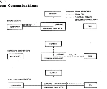
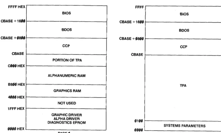
Subsystems Communications. Memory Architecture.
Character Keys • • Special Keys
Graphics Display •
•
• •
•
Parameter Array Contents •
DrawString Parameter Array Contents. SxS Graphics Character Cell.
Scan Out Parameter Array Contents. Crosshr Parameter Array Contents • Parameter Array Contents
Exterior Fuse Location • Good Fuse.
Blown Fuse • Serial Number. RS-232C.
RS-422 Fuse
•
Voltage Switch • • •
Two-Prong Power Cord Connection •
TS 800 User's Manual
LIST OF TABLES
1-1 Notation Conventions
.
.
.
.
.
.
.
.
.
.
.
2-1 2-2 3-1 3-2 3-3 4-1 4-2 4-3 5-1 5-2 5-3 5-4 5-5 5-6 5-7 5-8 5-9 5-10 5-11 5-12 5-13 6-1 6-2 6-3 6-4 6-5 7-1 G-1 G-2 H-l H-2 H-3 M-1
Switch Settings. • • • • • • • • • • • • • • • Printer and Modem Baud Rate Switch Settings • • • •
·
·
.
.
Special Keys 1 • • • • • • • •Special Keys 2 • • • • • • • • • Numeric Keypad Special Keys • • •
.
.
.
.
.
. . . .
. . .
. . .
.
. .
.
.
. .
.
.
.
.
.
.
CP/M Control Functions • • • • •Common Filetype Extensions • • • • • • •
Technical Terms. • • • • • • • • • •
·
• •.
Video Attributes • • • • • • • • • • • • • Escape Sequences for Video Attributes. • • • • • • Clear Commands Escape Sequences. • • • • • • • • • • • Cursor Display Escape Sequences • • • • • • • • • • • • Cursor Control Commands • • • • • • • • • • • • • • Cursor Coordinates • • • • • • • • • • • • Tab Controls • • • • • • • • • • • • • • • • • • • • • Editing Commands • • • • • • • • • • • • • • • • • Monitor Mode Control Characters • • • • • • • • • • • • Function of Special Keys • • • • • • • • • • • • •Keyboard Audio Commands • • • • • • • • • • • • Default Function Key Values • • • • • • • • • • • • Function Key Values. • • • • • • • Graphics Driver Functions. • • • • • • • • • • • • Fill Interior Styles • • • • • • • • • Graphics Styles. • • • • • • • • • • • • • • • • • Mouse Functions. • • • • • • • • • • • • • • • • • Character Font • • • • • • • • • • • • • •
Troubleshooting Procedures
.
.
. .
Port Addresses • • • • • • CRT Controller Control Register Port Board Connectors • • • • • • • • • • RS-232C Modem Connector • • • • • • • Serial Printer Connector • • • • • • Escape Sequence List • • •·
.
. . .
.
.
.
. .
. . . .
. . .
.
.
. .
.
.
.
. .
.
TS 800 User1s Manual
1. INTRODUCTION
INTRODUCTION TO THE TS 800
Welcome to the TeleVideo world of CP/M network computers! Your new workstation is designed to meet a wide variety of business needs and the user-friendly architecture makes the TS 800 easy to install and use. The TS 800 can be connected as either a
workstation or a service processor terminal to any of TeleVideo's network systems.
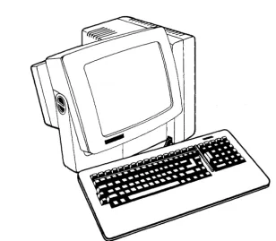
Figure 1-1
TS 800
You do not need technical expertise to set up and install your workstation. This manual describes the installation procedure step-by-step and also teaches how to best utilize the many features of the system for your own needs.
Please take the time to read the installation instructions and familiarize yourself with the operation of your system. The
special sections on using CP/M, and on programming give you added information for utilizing your system for more than word
TS 800 User's Manual
LIMITED W~
The TS 800 is covered by a limited warranty. The terms and conditions of the complete limited warranty are provided in Appendix B.
DESCRIPTION
Your TS 800 is an 8-bit workstation that utilizes Zilog's Z80A microprocessor. The system's tilt-adjustable, fourteen-inch CRT screen has a P31 green phosphor color that makes viewing easier on the eyes.
The computer's processor is designed to allow both alphanumeric computing and standard business graphics. The alphanumeric display is 24 lines by 80 characters. The graphics display
features a resolution of 640 x 240 pixels (squares on the screen, like a graph).
The standard system memory is 64 kilobytes (64K) which is expandable to 128K. If you want to use a printer for paper copies of your work, a modem for telecommunications, or a
SuperMouse for simpler computer interaction, there are ports, or connectors, on the rear panel to do this.
The TS 800 can be used for a variety of standard and unique applications. Some of the more common uses include:
Word processing
Data base management
Financial planning and analysis Business calculations
General accounting
Medical and dental record keeping
Customization of applications programs Programming
*
*
*
*
*
*
*
*
*
Graphics capabilities with many applicationsThe graphics capability allows you to construct graphs, and bar and pie charts for business graphics presentations. You can use graphics as an integral part of many applications programs.
TS 800 User's Manual
By adding a mouse, many graphics and menu-driven applications programs become even easier to use. Contact your computer store for further information about TeleVideo's SuperMouse.
Hardware
The hardware in the TS 800 includes the various parts of the
computer. These include the main unit, and the keyboard. The TS 800 is connected to one of TeleVideo's networking systems through the RS-422 port on the rear panel of the workstation.
Figure 1-2 shows the TS 800 with other possible hardware peripherals that your system can accept.
Figure 1-2
TS 800 with Hardware Peripherals
Software
TeleVideo's networking systems are controlled by the MmmOST
TS 800 User's Manual
Software for the TS 800 consists of those applications programs that have been installed on the central service processor.
There are two types of applications programs available to the network user:
Single-user programs such as
*
*
*
*
Word processing Business graphics
Financial planning and analysis Software development
Multi-user programs such as
*
*
*
*
*
Data base management General accounting
Medical and dental record keeping Remote data processing
Electronic mail
Your computer store representative can recommend applications software for your networking system.
Graphics
The graphics capabilities of the TS 800 allow you to use business graphics applications programs for creating graphs and charts for your business needs. Chapter 7 teaches the programmer how to access the TS 800's integral graphics capabilities at the assembly language level.
FORMAT OF MANUAL
There are a few conventions used in this manual that you should understand. Special notes throughout the manual draw your
attention to particular information. Symbols are used to indicate particular keys in various instructions.
Special Notes
Two types of notes call attention to information of special importance:
NOTE! STOP!
General note giving information to every operator. Note giving information concerning the safety of the operator, possible damage to the system, or possible loss of data. When you see this, STOP and read the note before proceeding!
TS 800 User1s Manual
Step-by-step procedures are used in this manual to show how to perform various functions. These procedures show what the user types in and how the system responds to that action. The
following is an example of the procedure format: USER: 1. User Action
(What you type in) SYSTEM: 2. Screen Display
(What you see on your screen)
Read the entire procedure before beginning the operation and completely read the step you are working in before entering a response. Many steps offer a choice. All user actions are shown in bold print.
Notation Conventions
Throughout this manual, the following symbols are used to describe user actions.
Table 1-1
Notation Conventions Symbol
<CR> "C
ESC
/
Key RETURN
(Carriage Return) CTRL (Control) C
LOC ESC/ESC (Escape)
Action
This symbol indicates that you are to press the RETURN key.
This symbol indicates that you are to press the CTRL and C keys
simultaneously. The A symbol can
be used with any alphanumeric character.
This notation indicates that you are to press the LOC ESC/ESC key. This symbol, when used between two keys, indicates that you are to press the two keys simultaneously. For example, SHIFT/LOC ESC
indicates to press the SHIFT and LOC ESC keys at the same time. Programmer1s Quick Reference Guide
The Programmer's Quick Reference Guide summarizes all control and escape commands for display control as well as the switch
TS 800 User's Manual
2. SETTING UP YOUR TS 800
INTRODUCTION
Your TS 800 was tested and inspected before it was packed for shipment. Inspect it carefully when you receive it.
After identifying the parts of your system, follow the directions to install it. Installation includes finding a suitable
location, checking and attaching the components, setting
switches, and determining the power requirements. Included in this chapter are directions for connecting a printer, modem, and mouse.
SELECTING THE RIGHT LOCATION
Select a sturdy, level surface. Leave at least four inches of free space around the enclosure for proper air flow.
Figure 2-1
Example Work Space
General Environment
The TS 800 operates best at temperatures and humidity levels in which you are also comfortable. Sudden and drastic temperature changes may adversely affect your stored data.
TS 800 User's Manual
CHECKLIST OF COMPONENTS
As you unpack, check to make sure you received the following items:
1. TS 800 including: Keyboard
Main unit with CRT (screen) Power cord
2. Documentation consisting of: TS 800 User's Manual
NOTE! IF ANY ITEM IS MISSING, CONTACT YOUR COMPUTER STORE BEFORE PROCEEDING WITH THE INSTALLATION.
Reader Comment Card
Your comments about this manual are welcome. To facilitate this, we have provided a Reader Comment Card in the back of the manual. Please take a moment to complete and return the card after you have installed your system.
INSTALLING YOUR SYSTEM
After selecting a good place for your computer and checking for all the parts of your system, it is time to install your TS 800.
Place the keyboard in a position that is comfortable for you. Plug the telephone-type coiled cord that is connected to the front of the main unit into the phone jack outlet on the back of the keyboard.
Figure 2-2
Keyboard Connection
Locate the ON/OFF power switch on the rear panel of the main unit. Be sure the power switch is turned off by pressing the plain end of the switch.
TS 800 User's Manual
Figure 2-3
Power Switch Off
()
POWER -J---JJ!Ull~-IIl~-~~;;;;;;;;;;;;;;;;;;;;;;;~---I~ SWITCH
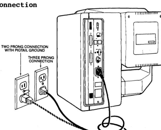
Power Cord Connection
The power cord tha t carne with your system plugs into the back of the main unit as shown in Figure 2-4. The source power supply and proper connections are described here.
The TS 800 requires a three-prong electrical outlet. If you do not have one and need an adapter, or if you are adapting the TS 800 for 230 volts, refer to Appendices E and F.
Plugging in the Power Cord
Plug the power cord that you received with the TS 800 into the plug on the back of the unit as shown in Figure 2-4.
Plug the other end of the power cord into an electrical outlet as you would any appliance.
Figure 2-4
Power Cord Connection
TWO PRONG CONNECTION WITH PIGTAIL GROUND
TS 800 User's Manual Line Voltage Regulator
We recommend using a line voltage regulator. By using a line voltage regulator, you can safeguard your system from power surges and voltage spikes that may interfere with the normal operation of your system. Contact your computer store for information on availability and installation.
Switch Settings
Switch settings control many functions, including video display. Most switches can be set according to your preference, but some must be set in required positions.
During installation it is important that you check the switch settings to match your system requirements.
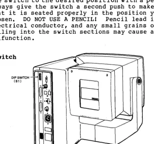
The TS 800 has one switch, called a DIP switch, located on the rear panel and labeled Sl. See Figure 2-5. This switch
contains ten sections (they look like small levers). These sections control various system functions. Figure 2-6
illustrates the positions of the sections as they are set by TeleVideo (default settings).
If you want to change any settings, see Table 2-1 for alternative switch settings.
STOP 1
Figure 2-5
The sections of the DIP switch are small individual switches. The top of each lever has a small recess that accepts the tip of a ball-point pen. Gently push the switch to the desired position with a pen, and always give the switch a second push to make certain that it is seated properly in the position you have chosen. DO NOT USE A PENCIL! Pencil lead is an electrical conductor, and any small grains of lead falling into the switch sections may cause a
malfunction.
Rear Panel Switch
TS 800 User's Manual
Figure 2-6
Default Switch Sections (as set by TeleVideo)
Q O'l <Xl r--co L() .q-C') C\J CLOSED
t-"'=~---NOT USED
OPEN
t-=-=~---GREEN ON BLACK SCREEN
CLOSED
r = = - - - N O T USED CLOSED
\ - = = = - - - - -REQUIRED OPEN
~"'-=---REQUIRED
OPEN
~'-'---REQUIRED
CLOSED
1 - = = : . . . - - - -REQUIRED CLOSED
r=~'---BAUD RATE
CLOSED
r==~----BAUD RATE
CLOSED
t-='=~----BAUD RATE
Table 2-1 lists all the possible settings for the DIP switch. Read through the t~ble, and set the sections according to your requirements.
Table 2-1
Switch Settings
Default Setting (set to right Section or left)
1 closed (r ight) 2 closed (right)
3 closed (right) 4* closed (right)
5 open (left) closed (right) 6* open (left) 7* closed (right)
8 closed (right)
9 open (left) closed (r ight) 10 closed (right) * Required settings
Function
Baud rate (see Table 2-3) Baud rate (see Table 2-3) Baud rate (see Table 2-3)
Workstation (default)
Service processor terminal
Not used
Green on black screen (default) Black on green screen
TS 800 User's Manual
CONNECTING THE TS 800 AS A WORKSTATION
This section describes the installation of the TS 800 in the
network environment as a workstation. In this mode the user has access to shared resources and files, although each user has his own independently operating system software.
Cable Connections
When operating as a workstation, the TS 800 should be within 1000 feet of the service processor. Refer to the section "Attaching Cables" for more information.
Attach one end of an RS-422 interface cable to the TS 800 RS-422 connector and the other end to anyone of the ports labeled USER on the rear of the TS 806/20 or TS 816/40 (shown in the respective User's Manuals.)
Switch Settings
The following steps describe dip switch settings for user station operation. Refer to Table 2-1 for additional switch settings. 1. DIP switch Sl-4 must be closed.
2. DIP switch Sl-5 must be open. 3. DIP switch Sl-6 must be open.
CONNECTING THE ~S 800 AS A SERVICE PROCESSOR TERMINAL
This section describes the installation of the TS 800 in the
network environment as a service processor terminal. In this mode, the TS 800 serves as the terminal through which an operator
controls the entire network; it is dedicated to the service processor and cannot function as a user station.
Cable Connections
When the TS 800 is used as a service processor terminal, the cable connecting it to the central service processor should not exceed 100 feet. Refer to the section Attaching Cables.
Attach one end of an RS-232C interface cable to the connector labeled TERMINAL on the rear of the TS 806/20 or TS 816/40 case (as shown in their respective User's Manuals.) Attach the other end to the RS-232C connector labeled RS-232 on the rear of the TS 800. (The pin assignments for the terminal connector are furnished in Appendix H.)
TS 800 User's Manual
NOTE! The RS-232 port has two switch-selectable
configurations: it can be used to attach a modem to the TS 800 stand-alone system, or it can be used to attach the TS 800 to a TS 806/20 or TS 816/40 as a
service processor terminal. A MODEM CANNOT BE ATTACHED TO THE TS 800 WHEN IT OPERATES AS A SERVICE PROCESSOR TERMINAL.
Switch Settings
Certain switch settings are required for the TS 800 to operate as a service processor terminal:
1. DIP sw itches 4 and 5 must be closed and 6 must be open. 2. The system is set at the factory for a baud rate of 9600,
but you can change this to meet the requirements of the service processor. The baud rate is controlled by DIP switches Sl-l, Sl-2, and Sl-3 on the rear of the TS 800. Make sure the TS 800's baud rate matches that of the central service processor. If you are using the TS 800 with the TS 806/20 or TS 816/40, DIP switches, Sl-l, Sl-2 and Sl-3 should be closed. These settings are for 9600 baud rate. Refer to Switch Settings in Chapter 2.
NOTE! I f you are not con n e c tin gap r in t e r 0 r mod e man dar e
ready to use your system, go to the Checklist of Installation Procedures at the end of this chapter before continuing with Chapter 3, Power On.
If you wish to connect a printer or modem to your system, continue reading this chapter.
TS 800 Userls Manual CONNECTING PERIPHERALS
Auxiliary serial devices such as printers, modems, plotters, and mice can be connected to the TS BOO. Instructions are given here for connecting each of these. The serial printer interface
allows the TS BOO to be used with most RS-232C-compatible serial
printers currently available on the market, including both
character-by-character and buffered printers. The TS BOO is also
equipped with a serial modem port for data transmission to another location over telephone lines.
The setup Program allows you to quickly and easily change the printer and modern port baud rate and data format to adapt to a variety of peripherals. You can also indicate to the operating system whether or not a mouse is attached. A complete
description of the capabilities of the Setup Program, as well as step-by-step instructions for using it, are in Appendix L.
Attaching Cables
Cables are needed to connect the TS BOO to a printer or a modem.
The types of cables needed are determined by the requirements of the device(s) attached to the TS 800. You can obtain the
appropriate cables for attaching peripheral devices at your computer store. The technical specifications for each type of cable can be found in Appendix D.
Cable connectors commonly have D-shaped end connectors. See Figure 2-7. These fit onto a D-shaped pin connector on the rear panel of the system. To install a cable, turn the connector end of the cable to fit the pin connector on the device, then gently push the cable on the pin connector. The screws can be finger tightened to prevent accidental cable disconnection.
Figure 2-7
n-Shaped Cable Connector
Leave some slack as you connect the cables. If you are using a round cable, coil it loosely and secure it with a rubberband. If you are using a flat, ribbon cable, fold it accordion-style as shown in Figure 2-B. Coiling the ribbon cable can adversely affect system performance.
TS 800 User's Manual
Figure 2-8
Correctly Folded Excess Ribbon Cable
Connecting a Serial Printer
The RS-232C serial port labeled PRINTER is ready to connect to a serial printer when the unit is shipped from the factory. The TS 800 is set to work with printers that run with DTR protocol. Refer to Appendices I and J for further information. Be sure to read the instructions that came with your printer for correct interfacing information. The TS 800 and printer should be within 50 feet of each other. Refer to Appendix D for cable
specifications.
Attach one end of an RS-232C interface cable to the port labeled PRINTER. Attach the other end to the RS~232C pin connector on
the printer.
NOTE! Addresses for RS-232C ports are given in Appendix G.
The computer and the peripherals must run at the same speed in order to work properly. This speed is called the baud rate. Baud rates are determined by the switch settings. Table 2-2 shows the proper switch settings for changing the baud rate to correspond with various printers and modems. The baud rate can also be changed by using the Setup Program as described in
TS 800 User's Manual
Table 2-2
Printer and Modem Baud Rate Switch Settings
Legend
DIP Switch Section
I 2 3
C C C
o
C CC 0 C
o
0 CC C 0
o
C 0COO 0 0 0
C = Switch closed (right)
o
=
Switch open (left)Baud Rate
9,600 (default) 4,800
2,400 1,200 600 300 150
75
Changing the Default Printer Device
To change the default printer device and to establish different power-up default values, refer to the instructions in Appendix I, or the Setup program in Appendix L.
Connecting a Modem
You can connect one modern to the TS 800. The RS-232C port labeled RS 232 is ready to interface to a modern.
The TS 800 and modern should be within 50 feet of each other. Refer to Appendix D for cable specifications.
Attach one end of an RS-232C interface cable to the port labeled
RS 232. Attach the other end to the modem's RS-232C pin
connector.
Modern baud rate at default is 9600 baud, but it can be changed by the Setup program in Appendix L or by changing the switch
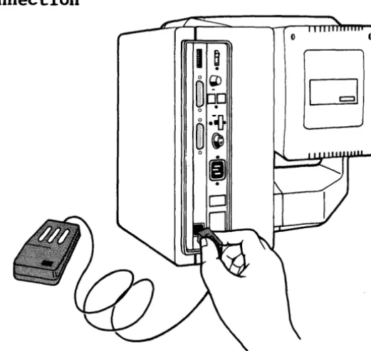
settings. See Table 2-2. Connecting a Mouse
The TS 800 is equipped with a port already configured to accept TeleVideo's SuperMouse. To install the SuperMouse, plug the connector on the SuperMouse cord into the modular telephone-jack
in the back of the TS 800 (See Figure 2-9). Use the Setup Program (Appendix L) to set the operating system default to
"mouse attached." Follow the instructions supplied with the SuperMouse for operational information.
TS 800 Userls Manual
Figure 2-9
SuperMouse Connection
o 0
Your TS 800 system is now installed. At this point you can
position the computer where you want it and adjust the screen for your comfort by tilting it up and down. When it is in the
position you wish, turn the flat knob on the left side of the screen in a clock-wise direction until it is tight. See Figure 2-10.
Figure 2-10
TS 800 User's Manual
CHECKLIST OF INSTALLATION INSTRUCTIONS
Before you proceed with the operation of the system, check your installation.
1. Did you check the TS 800 for possible shipping damage? 2. Is the location that you selected:
Supplied with a steady line voltage?
Within comfortable temperature and humidity levels? Clean?
Providing sufficient ventilation around the case?
3. Is the telephone-type coiled cord plugged into the keyboard? 4. Is the power switch turned off?
5. Is the power plug correct for the electrical power outlet? Is it plugged into a grounded electrical outlet?
6. Is the system properly connected to the Service Processor? 7. Is the switch Sl set correctly? For all peripheral devices? 8. If the TS 800 is connected to a serial printer and/or a
modem, are they connected and located within the distance limits specified?
If the answer to all of these is YES, then you are ready to go on to Chapter 3, Power On.
~
TS 800 User's Manual
3. POWER ON
INTRODUCTION
This chapter gives a step-by-step guide for turning on your
workstation, adjusting the contrast, and understanding and using the keys on the keyboard. There is also a section how to use applications programs. The last section shows you how to turn the computer off.
INITIAL START UP
This section describes the process of starting up the TS 800 in the MmmOST network.
Powering Up the TS 800 as a Workstation
1. Check the switch settings (refer to the section, Switch Settings, under Connecting the TS 800 as a Workstation). 2. Make sure the service processor is on and has successfully
booted from the hard disk drive.
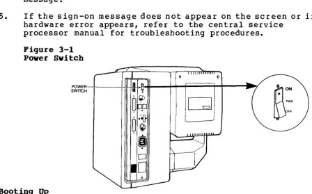
3. Locate the power switch on the rear of the TS 800. Power up the system. (See Figure 3-1.)
4. Look for this message on the TS 800 screen: TeleVideo Systems xxk CP/M V2.2
(c) 1983 TeleVideo Systems, Inc. Distributed Processor TS-800 V x.y Processor ID xx
<=)
y5. CP/M is now in the TS 800 memory and you are ready to operate.
6. If this message does not appear, refer to the
troubleshooting chapter of the Central Service Processor.
7. If a hardware error message appears, refer to the section Self-Tests During Power On and Reset.
Powering Up the TS 800 as a Service Processor Terminal
1. Check the switch settings (refer to the section, Switch Settings, under Connecting the TS 800 as a Service
Processor) •
TS 800 Userls Manual
3. Power up the service processor.
4. Look for a sign-on message on the TS 800 screen. Refer to the central service processor manual for the correct
message.
5. If the sign-on message does not appear on the screen or if a hardware error appears, refer to the central service
processor manual for troubleshooting procedures. Figure 3-1
Power Switch
o
POWER---+---!-+~~:~~-+_+....,;;;;;;;;;;;;;;;;;;;;~_+--. . _7
SWITCH
Booting Up
Boot is a term that describes the process of the computer starting itself up. It is derived from the expression "pull yourself up by the bootstraps."
There are two types of boots - a cold boot and a warm boot. Each one affects your system in a different way.
A cold boot, or cold start, refers to the process of turning the workstation on and loading the operating system. When the power is turned on, the system performs a self-diagnostic test
(described in the following section). When the diagnostic test is successfully completed, the system memory is cleared and the operating system is loaded into the workstation.
A system reset, or reset, is similar to the cold boot. A reset will terminate all current activity and then clear system memory and reload the operating system. All data in memory that has not been saved on disk is lost.
Restart the system if you have a problem with a program and you wish to start again, or if the system does not respond correctly. For example, you would reset the system when the cursor freezes. To reset your system, press the CTRL and the RESET (ARESET) keys simultaneously.
TS 800 User's Manual
A warm boot is primarily used to interrupt and stop the execution of a CP/M command. When you press .... C, the warm boot command, the system prompt appears on the screen. Applications programs have their own warm boot commands to allow you to return to the
operating system prompt.
To warm boot the TS 800, enter .... C (press the CTRL and C keys
simultaneously) either as the first character entered in response to a system prompt, or in applications programs when allowed.
Self-Tests During Power On and Reset
When the TS 800 is first powered on, several tests are performed to check the system functions. These tests make sure there are no hardware problems that could prevent the operating system from loading, damage the user programs, or destroy data.
If there are any parts that do not pass the tests, an error message appears on the screen. This message states the problem and then says to contact your distributor. Try to reset the system again before calling your computer store.
NOTE! These tests are not performed when the TS 800 is warm booted - only at cold boot.
If no messages appear, reset the system by pressing .... RESET. (If necessary, refer to the Troubleshooting section in Chapter 7.) Cursor
The blinking rectangular block on the screen is called the cursor. The cursor shows you where data typed on the keyboard will appear on the screen. As the cursor reaches the end of a line, it automatically goes down, or wraps around, to the
beginning of the next line. System Prompts
On your TS 800, the system prompt for drive A of the service processor looks like this:
A)
Prompts vary from one computer system to another but almost always indicate that the operating system is ready for your
response. While using an applications program, you may see a different prompt symbol; this will be explained in the
TS 800 User's Manual
Adjusting the Contrast
Adjust the contrast by turning the contrast knob on the rear
panel of the system for the desired screen intensity. See Figure
3-2.
Figure 3-2 Contrast Knob
CONTRAST KNOB~--....I...J..I!.~-U
KEY DESCRIPTIONS
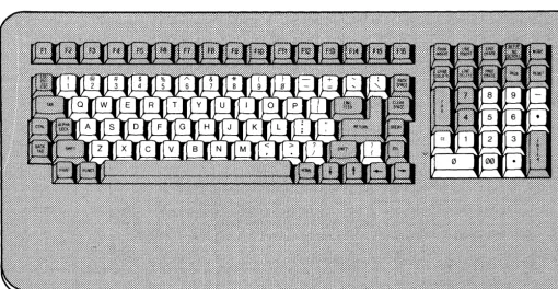
The keyboard has a Selectric-style format with a separate numeric keypad for accounting applications. This means that the keyboard operates like a typewriter with many of the same special keys and capabilities to do tabbing and other typewriter functions.
Figure 3-3 Keyboard
TS 800 Userls Manual Character Keys
The character keys that are highlighted in Figure 3-3 are arranged as they are on a typewriter.
The character keys include all alphabet characters (A through Z), numbers (0 through 9), punctuation marks, and mathematical
symbols. All character keys repeat when pressed for more than one-half second.
Special Keys
There are several special keys that make inputting information easier. The three sections on the following pages include
descriptions of the special keys on each side of the main keypad and the special keys on the numeric keypad.
Many of the special keys are not programmed to be used according to their labels when you are using CP/M, the operating system. Therefore, if you use them you may see some symbols and
characters on the screen that do not seem to make any sense. A programmer can customize these keys to a specific applications program.
The following descriptions are a general guide for what each key does when you are using CP/M. Programmers can refer to the
Keyboard section in Chapter 6 for a more detailed description of the keys.
TS 800 User's Manual
Table 3-1
Special Keys 1
Key Name Space Bar SHIFT
ALPHA LOCK
TAB
BACK TAB
CTRL (Control)
LaC ESC/ESC
FI through Fl6 (Function Keys) PRINT
Description
Works like the space bar on a typewriter. Like the SHIFT key on a typewriter it selects the upper character inscribed on a key,
changes operation of most special keys, and capitalizes alpha characters.
Like the typewr iter SHIFT key, it must be pressed down simultaneously with the key to be shifted. In this manual, when you see SHIFT/ it means to simultaneously press SHIFT and the key that follows the slash.
Locks the SHIFT keys so that all alpha keys are upper-case characters. The key is
pressed to lock and pressed again to release. Moves the cursor forward one tab.
Moves the cursor to the first column on the line when used in the key sequence SHIFT/LaC ESC, BACK TAB.
The control key combinations are used for special action by the computer and/or the applications program in the computer.
The CTRL key is always used simultaneously with the other character in the command; the CTRL key is pressed first and held down while the other key is pressed. Use of the CTRL key is indicated in this manual by the symbolA.
This key is generally used to momentarily leave (escape) an applications program in order to use a special feature or function. ESC is unshifted. LOe ESC is shifted.
The ESC key is used with another character(s) in the command sequence; the ESC key is
pressed and released before the second key is pressed.
Certain applications programs enable these keys to perform special functions.
The PRINT key does not activate printing in CP/M. All print functions are software controlled.
TS 800 User's Manual
FUNCT
Figure 3-5 Special Keys 2
The FUNCT key is not used on the TS 800.
-Table 3-2
Special Keys 2 Key Name
RETURN and ENTER
LINEFEED
BACKSPACE
CLEAR SPACE
Description
The RETURN and ENTER keys can be used interchangeably. When the RETURN key is pressed, the action on the screen is like a carriage return. In this manual, when you are to press the RETURN or ENTER key, you will see this:
<CR)
This key moves the cursor down one line on the screen when used in the sequence
SHIFT/LOC ESC, LINEFEED. When pressed alone, it works the same as the RETURN key.
Moves the cursor one character to the left and deletes that character. Same as arrow
left.
When you press SHIFT/LOC ESC, CLEAR SPACE, all characters on the screen are replaced with spaces.
Shifted CLEAR SPACE clears the graphics
TS 800 User's Manual
DEL (Delete)
HOME
Arrow Up
Arrow Down
Arrow Right
Arrow Left
BREAK
Figure 3-6
Deletes the character to the left of the cursor. The character(s) that are deleted are displayed (echoed) on the screen.
Pressing SHIFT/LOC ESC, HOME moves the cursor to column one of row (line) one. This
position is referred to as the home position. Moves the cursor up one line when pressed in the sequence SHIFT/LOC ESC, arrow up.
Moves the cursor down one line when pressed in the sequence SHIFT/LOC ESC, arrow down. Moves the cursor one character to the right when pressed in the sequence SHIFT/LOC ESC, arrow right.
Moves the cursor one character to the left without deleting that character when used in the sequence SHIFT/LOC ESC, arrow left.
Moves the cursor one character to the left and deletes that character when used alone. The BREAK key is not used in CP/M.
Numeric Keypad Special Keys
TS 800 User's Manual
Table 3-3
Numeric Keypad Special Keys Key Name
CHAR INSERT
LINE INSERT
LINE ERASE
CHAR DELETE
LINE DELETE
RESET
TAB
MODE
CE
PAGE
PAGE ERASE
SET UP/NO SCROLL
Description
When pressed in the sequence, SHIFT/LOC ESC, CHAR INSERT, causes character at the cursor to move right one column position and enters a space at the cursor position.
Inserts a line consisting of spaces at the cursor position when used in the sequence, SHIFT/LOC ESC, LINE INSERT.
Deletes all characters from the cursor to the end of the line when used in the sequence, SHIFT/LOC ESC, LINE ERASE.
Deletes the character at the cursor position and moves all following characters left one position when used in the sequence, SHIFT/LOC ESC, CHAR DELETE.
Deletes the line at the cursor position and all following lines move up one line when used in the sequence, SHIFT/LOC ESC, LINE DELETE.
Used with the CTRL key to reset the system. In this manual, this sequence is written ARESET.
Causes the cursor to advance to the next set tab.
The MODE key enables the user to toggle the display from graphics to alphanumerics and vice versa without affecting the running program.
The CE (clear entry) key erases the current line and moves the cursor back to the prompt. The PAGE key is not used on the TS 800.
The screen is erased from the cursor position to the bottom of the screen when keys are pressed in the sequence, SHIFT/LOC ESC, PAGE ERASE.
TS 800 User's Manual
RONNING APPLICATIONS PROGRAMS
You may have purchased an applications program such as a word processing program or an accounting program for your system. The following procedures describe how to load the TeleWrite word
processing program installed on the B drive of the central service processor.
In this example the command to call up TeleWr i te is TW. Find the call-up command for you applications program in the documentation that accompanies it.
SYSTEM: Displays
A)
USER: To make B the logged drive, enter: b:<CR)
SYSTEM: Displays
B)
USER: To start TeleWrite, enter tw<CR)
At this point, TeleWrite (or your applications program) is loaded into the workstation from the B drive on the central service
processor. From here, follow the instructions that came with the applications program.
Using CP/M, the Operating System
Wh en you s tar t the s y s tern and you see the A) pro m p t, you are in CP/M, the operating system for the TS 800. The operating system contains all the instructions that make the computer work. It also contains some programs and commands that can be useful to you as you use your applications programs.
When you type in commands, CP/M recognizes either upper- or lower-case letters even though its responses are in capital letters.
See Chapter 4 for a complete descr iption of CP/M and its many uses.
TS 800 User's Manual
4. USING CP/M, THE OPERATING SYSTEM
INTRODUCTION TO CP/M
CP/M stands for "Control Program/Monitor" or "Control Program for Microcomputers." CP/M is a computer program, just like a word processor or accounts payable package. CP/M is called an
operating system because it controls all the operations and programs in your computer.
CP/M controls the read and write operations to the network's disk drives. It loads the various applications programs that you want to run and supervises their execution. It organizes the data for communications to a printer or over a modem to a remote station. One way to think of CP/M is as the "personality" that resides in your computer; it is the over-all set of commands that you use to run everything else on your system.
CP/M TERMS
As you read through this chapter, look for the following technical terms:
cold boot system prompt resident command command line operating system
warm boot logged drive
transient command user memory area
They describe some basic concepts in computing. By mastering these few terms you will find yourself inside the "computerese" club! To help you there is a review of the terms at the end of this chapter.
STARTING UP CP/M
TS 800 User's Manual
Reset Command
The following paragraphs explain how to use the CP/M commands.
If you enter a command that doesn't seem to work, or if the
system "freezes" after you enter a command, remember that you can always re-start (cold boot) CP/M by pressing ARESET. The
computer will clear memory and re-Ioad the CP/M operating system. This is the same as turning the power on.
SYSTEM PROMPT AND THE LOGGED DRIVE
When CP/M is successfully loaded into memory from the system, the system prompt is displayed at the left margin of your screen:
A)
The system prompt tells you that CP/M is waiting for your next command which will be displayed to the right of the greater-than character as you type it in. The A in the prompt tells you that the logged drive is disk drive A.
The logged drive is the disk drive that CP/M is currently working from. For example, if you want to look up the status using the STAT command for a file on disk, and you don't specify which disk drive the file is on, CP/M assumes that you mean the logged
drive. You can change the logged drive with this command: A)b:(CR)
B)
The second line is CP/M's response, showing you that the logged drive is now B and that it is ready for another command.
CP/M COMMAND LINES
CP/M takes your commands in the form of a command linee A
command line is a string of characters that names the command and supplies any data necessary (such as a filename). The command line is terminated and sent to the computer for processing when you press the RETURN «CR» key.
CP/M also accepts several "control" characters, such as ~C, as commands. These are directly interpreted ~ithout entering <CR), and are useful for editing a command line or entering an override command.
TS 800 User's Manual
Upper- and Lower-Case
You may have noticed that CP/M accepted a lower-case "b" in the example above, but displayed an upper-case "B" in its response. CP/M does not distinguish between cases on characters that you type. You may find it convenient to enter commands in lower-case so that you can distinguish your entries from CP/M responses on the screen. When you name a file with lower-case letters, the name is displayed in upper-case letters in the diskette
directory.
NOTE! Please note that this is only a characteristic of CP/M: other programs such as BASIC do not behave in the same way.
Control Characters
The key marked CTRL (A) is the CONTROL key. To use the CTRL key,
press the CTRL and a character key simultaneously. For example, the command to restart CP/M is:
Press the CTRL and C keys simultaneously.
You use this command to abandon a program and to restart CP/M. Line Editing
CP/M has several control characters and single-key commands that allow you to edi t a complex command line before you send it to the computer with a <CR>. Table 4-1 summarizes the available functions:
Table 4-1
CP/M Control Functions Key
"'c
AE
BACK SPACE
Function
System warm boot; doesn't clear user memory. Physical end of line; cursor wraps to
beginning of next line, but <CR> not sent. Backspace; moves cursor back one space and deletes character that was there.
TS 800 User's Manual
DEL
"'p
RETURN ARESET
DISK PILES
Deletes character to the left of cursor. The character(s) that are deleted are
displayed (echoed) on the screen.
Moves the cursor to the next tab (8, 16,
24... ).
Activates the printer; deactivates the printer with a second Ap (toggle).
Re-display command line; useful after DEL echoes deleted characters on command line. After a file or a list starts to display on the screen, AS is pressed to start or stop
(toggle) the scrolling of the display.
Cancel current command line; positions cursor under command line for easy re-typing.
Backspace to prompt (erases current line). Works the same as the CE key.
Send command line to computer; <CR).
System cold-boot; clears memory and reloads CP/M from drive A.
The disk file is the basic unit of organization in CP/M. All resident commands refer to file operations. A file can hold any kind of information: text, machine language program code, or graphics commands. Every file is labeled with a unique filename, so that the computer can always find the exact file specified in a given command. Refer to the MmmOST manual for more information about disk file organization.
Filenames
A filename is composed of three parts: drive prefix:filename.extension A full unique filename might be:
A:ACCOUNTS.BAS
The drive prefix is a single letter that corresponds to the drive the file being referenced is loaded on. If you leave the drive prefix and colon off of the filename, CP/M assumes the currently logged dr ive.
The filename is a unique combination of letters and numbers that
TS 800 User's Manual
identifies the file in the disk directory. You can use one to eight characters in the filename, mixing numbers and letters any way you want to arrive at a file-naming scheme that is useful to you.
The extension is designated by a period at the end of the filename followed by three characters. It is useful for identifying different types of files in the disk directory. Table 4-2 lists some common filetype extensions.
Table 4-2
Common Filetype Extensions Extension
.ASM .BAK • BAS .COB .COM .DOC .HEX .REL .SUB .TXT
.$$$
Wildcard File References
Definition
Assembly program source file Back-up file
BASIC program source file COBOL program source file
CP/M executable file (transient command) Document file
Intel hexadecimal code file Relocatable machine code file SUBMIT command file
Text file
System temporary file
In the example above, you saw that you could leave off the drive prefix so that CP/M would supply the currently logged drive. This is handy for speeding up your file manipulation work. You can also insert special wildcard characters into a file
specification so that CP/M can find multiple files based on a controlling prefix or extension.
*
(asterisk) In the place of a filename or file extension means "substitute all directory entr ies here."? (question mark) In the place of one or several character positions in the file specification
TS 800 User's Manual
When CP/M finds a wildcard in a file specification it tries to do a file-match. It performs the desired command on all files that match the specification. For example:
A>STAT *.BAS<CR>
returns the status for all .BAS files on the logged drive (no drive prefix was given).
A>stat b:sam.*<CR>
returns the status for all files named SAM on drive B, regardless of their filetype extension. (Remember, CP/M converts lower-case to upper-case when you enter a command.)
Use the n?n wildcard for single- and multiple-character substitutions:
A>era d???*<CR>
erases all files on the logged drive that begin with ndn followed by up to three characters. (It also erases files that begin with nd n and have less than four characters.) This is known as a
file-match nmask.n The following erases all files beginning with the letter d:
A>era d*.*<CR> RESIDENT COMMANDS
When CP/M is loaded into memory it includes a kernel (core group) of built-in or resident commands. These are executable directly from their nhome n in memory.
CP/M also has a set of transient commands which stay in the system until they are needed. Transient commands are
actually small programs that are loaded into memory when you call them with a CP/M command line; they are cleared from memory when they are through executing (that is why they are called
ntransientn). This section describes the CP/M command line format for each of the resident commands.
The resident commands discussed below are: DIR
ERA REN
List a directory Erase a file Rename a file
TYPE Display or list a file on the screen
TS 800 User's Manual
Unrecognized Commands
If you type in a command that is not recognized by CP/M, usually by making a typing error, CP/M repeats the command as you entered
it on the next line followed by a question mark:
A>statt<CR> STATT?
A>
DIR -- List a Directory
The DIR command displays a directory of the files on a drive. A>dir x:filename.ext<CR>
Typing dir<CR> gives you a full directory listing for the
currently logged drive. You can narrow the listing down, or list the directory for a different drive by supplying a file
specification with or without "wildcard" characters.
ERA -- Erase a File
The ERA command erases the file or files specified. A>era x:filename.ext<CR>
In the special case of "erase all files" on a drive: A>era b:*.*<CR>
ERA responds with a safety verification: ALL (Y/N)?
Type Y to erase all the files, N to cancel the command, followed by <CR>.
REN -- Rename a File
Th eRE Nco m man dis use d tor en am e a f i l e i nth e d ire c tor y • A>ren newname.ext=oldname.ext<CR>
Notice that the replacement goes right-to-Ieft, that is, the existing file comes second in the command line and will end up with the name at the beginning. This "parameter order" is important! See the transient command PIP also.
TS 800 User's Manual
If you enter an incorrect file to be renamed, the computer won't be able to find it, and displays the message:
NO FILE
TYPE List a File on the Screen
This command displays the contents of a file on the screen: A)TYPE x:filename.ext<CR>
The computer sends information to the screen as fast as it can scroll, so a long file seems to fly by. Use the AS command to stop and start the scrolling action.
TRANSIENT COMMANDS
CP/M comes with a set of very useful utility programs called transient commands. Some of them are powerful program
development aids such as the text editor ED, a dynamic debugging monitor DDT, and a file printing routine called DUMP. You can see a list of the transient commands that are on your system by typing:
A)DIR *.COM
The filetype extension .COM is used to denote a file that contains an executable CP/M program or "COMmand." Buying programs is a matter of adding to the number of .COM files available to your system. For example, the word processing
program TeleWrite is usually stored in a file called "TW.COM." So the CP/M transient command to execute TeleWrite is:
A)tw<CR>
The program is loaded into the user memory area, or "Transient Program Area" (TPA) , and begins execution. When you leave
TeleWrite, the TPA becomes available again for another program. Two of the transient command programs supplied with CP/M are very useful to the beginning computer operator, and they are described below. For a description of the more advanced program development tools, refer to one of the books recommended in
Appendix C.
The two transient commands discussed below are:
STAT List the STATus of a file. Use this to get an alphabetical column display of the files on your drive.
PIP The Peripheral Interchange Program. Use this to move and to copy files.
TS 800 User's Manual
STAT -- List the Status of a File
The STAT command is used for a variety of tasks. The primary function is to list the status of a file, or files, or an entire drive on the screen. STAT can also be used to change the
protection status on a file or group of files. Finally, STAT can be used to change the status of the logical device assignments on your system.
To list the status of the files on a drive enter: A>stat
*.*<CR>
This causes a column listing of the drive files in alphanumeric order. This is often more useful than the DIR all-on-a-line listing. In addition to the sorted listing, STAT displays other useful information about each file. The STAT listing looks like this:
Recs Bytes Ext Acc
64 8k 1 R/W A:ASM.COM 4 2k 1 R/w A:DUMP.COM 58 8k 1 R/w A:PIP.COM 41 6k 1 R/W A:STAT.COM where:
Recs is the number of 128-byte records in the file. Bytes is the length of the file in bytes.
Ext is the number of logical extents (16k-byte blocks) • Acc is the file access status.
The file access sta tus can be used to protect valuable files from unwanted overwriting or accidental erasure. R/W means that a
f i 1 e can be Re a d fro man d W r itt en to. R/O mea n s t hat a f i 1 e can be Read Only. To change the access status of a file use the command line:
A>stat x:filename.ext $R/O
TS 800 User's Manual
PIP Peripheral Interchange Program
PIP is used to copy files from one drive to the other, or to copy I
a file to a different filename. The basic format for a PIP command is:
PIP y:file2.ext=x:filel.ext[zzzl(CR> where:
file2.ext
filel.ext
zzz x and y
is the ndestination" file, where the copy will end up
is the nsource n file, where the copy comes from
are nparametersn that allow special handling are the disk drives
Notice that, like REN, the action proceeds from right-to-left on the command line.
If you wanted to copy a file from drive A to drive B, the command line would look like this:
A>pip b:=a:myfile.bas<CR>
There are now two copies of the same data, one in the file
nMYFILE.BAS n on drive A, and one in file nMYFILE.BAS" on drive B. You may, or may not wan t to ERAse the old copy (disk space is a premium, so developing good housekeeping practices can help you get the most out of your system. Don't wait for a disk-full error!)
By omitting any drive specifications you can make copies of a file on the same disk.
One special parameter is very useful, and easy to append to the PIP command line:
v causes PIP to verify that the copy is an exact
duplicate of the original file by doing a byte-by-byte comparison. This may cause delays on long (200K plus) files.
If you wanted to use this paramet