University of Windsor University of Windsor
Scholarship at UWindsor
Scholarship at UWindsor
Electronic Theses and Dissertations Theses, Dissertations, and Major Papers
11-6-2015
Plasma Process Control for Improved PEO Coatings on
Plasma Process Control for Improved PEO Coatings on
Magnesium Alloys
Magnesium Alloys
Riyad Omran Hussein
University of Windsor
Follow this and additional works at: https://scholar.uwindsor.ca/etd
Recommended Citation Recommended Citation
Hussein, Riyad Omran, "Plasma Process Control for Improved PEO Coatings on Magnesium Alloys" (2015). Electronic Theses and Dissertations. 5523.
https://scholar.uwindsor.ca/etd/5523
This online database contains the full-text of PhD dissertations and Masters’ theses of University of Windsor students from 1954 forward. These documents are made available for personal study and research purposes only, in accordance with the Canadian Copyright Act and the Creative Commons license—CC BY-NC-ND (Attribution, Non-Commercial, No Derivative Works). Under this license, works must always be attributed to the copyright holder (original author), cannot be used for any commercial purposes, and may not be altered. Any other use would require the permission of the copyright holder. Students may inquire about withdrawing their dissertation and/or thesis from this database. For additional inquiries, please contact the repository administrator via email
Plasma Process Control for Improved
PEO Coatings on Magnesium Alloys
by
Riyad Omran Hussein
A Dissertation
Submitted to the Faculty of Graduate Studies
through Engineering Materials
in Partial Fulfillment of the Requirements for
the Degree of Doctor of Philosophy
at the University of Windsor
Windsor, Ontario, Canada
2015
Plasma Process Control for Improved PEO Coatings on Magnesium
Alloys
by
Riyad Omran Hussein
Approved by:
---
F. Cheng, External Examiner
University of Calgary
---
S. Das
Civil &Environmental Engineering
---
H. Hu
Department of Mechanical, Automotive, & Materials Engineering
---
V. Stoilov
Department of Mechanical, Automotive, & Materials Engineering
---
X. Nie, Co-advisor
Department of Mechanical, Automotive, & Materials Engineering
---
D. O. Northwood, Co-advisor
Department of Mechanical, Automotive, & Materials Engineering
III
DECLARATION OF CO-AUTHORSHIP / PREVIOUS PUBLICATION
This thesis includes 10 original papers that have been previously published in peer reviewed
journals and conference proceedings, as follows:
Chapter Publication title/full citation status
Chapter 2 A- Hussein R. O., Nie X. and Northwood D. O. (2013), The
Application of Plasma Electrolytic Oxidation (PEO) to the
Production of Corrosion Resistant Coatings on Magnesium
Alloys: a Review, Corrosion and Materials 38 (1), pp. 53-63.
B- Production of anti-corrosion coatings on light alloys (Al,
Mg, Ti) by Plasma Electrolytic Oxidation (PEO), Riyad O.
Hussein, Derek O Northwood, ‘In: Developments in Corrosion
Protection, (M. Aliofkhazraei, Ed.) InTech Open Publishers,
ISBN 980-953-307-1100-2. 2013
Published
Published
Chapter 4 A- Hussein R.O., Zhang P., Xia Y., Nie X. and Northwood
D.O (2011) The effect of current mode and discharge type
on the corrosion resistance of plasma electrolytic oxidation
(PEO) coated magnesium alloy AJ62, Surface & Coatings
Technology, 206 (7) , pp. 1990-1997.
B- Hussein R.O., Zhang P., Northwood D.O. and Nie X.
(2011) Improving the corrosion resistance of magnesium
alloy AJ62 by a plasma electrolytic oxidation (PEO)
coating process, Corrosion and Materials 36 (3), pp. 38-49.
Published
Published
Chapter 5 Hussein R. O., Northwood D. O. and Nie X. (2014)
Processing-Microstructure Relationships in the Plasma
Electrolytic Oxidation (PEO) Coating of a Magnesium Alloy,
Materials Sciences and Applications (MSA), 5 (3), pp. 124-139
Published
Chapter 6 Hussein R. O., Northwood D. O., Su, J.F. and Nie X. (2013) A
study of the interactive effects of hybrid current modes on the
tribological properties of a PEO (plasma electrolytic oxidation)
IV
coated AM60B Mg-alloy, Surface & Coatings Technology,
215, pp. 421–430.
Chapter 7 Hussein R. O., Nie X. and Northwood D. O. (2013) An
investigation of ceramic coating growth mechanisms in Plasma
Electrolytic Oxidation (PEO) processing, Electrochimica Acta
112, pp. 111-119.
Published
Chapter 8 Hussein R. O., Northwood D. O. and Nie X. (2013) The effect
of processing parameters and substrate composition on the
corrosion resistance of plasma electrolytic oxidation (PEO)
coated magnesium alloys, Surface & Coating Technology, 237,
pp. 357-368.
Published
Chapter 9 Hussein R. O., Nie X. and Northwood D. O. (2013) Effect of
cathodic current density on the corrosion protection of the
oxide coatings formed on AZ91D magnesium alloy by plasma
electrolytic oxidation. Corrosion and Prevention 2013”,
Australia 2013, paper no. 112.
Published
Chapter 10 Hussein R. O.,Nie X. and Northwood D. O. (2014) The roles
of the electrolyte composition and concentration on the
corrosion resistance of the oxide coatings formed on AZ91D
magnesium alloy by plasma electrolytic oxidation, Corrosion
and Prevention 2014; Australia 2014; Code 109535
Published
I certify that I have obtained a written permission from the copyright owner(s) to include
the above published material(s) in my thesis. I certify that the above material describes
work completed during my registration as graduate student at the University of Windsor.
I am aware of the University of Windsor Senate Policy on Authorship and I certify that I
have properly acknowledged the contribution of other researchers to my thesis, and have
obtained written permission from each of the co-authors to include the above materials in
V
In all ten original published papers I was the sole student investigator on the projects
reported and had a major role in conducting the wear test, surface analyses and the
preparation of the manuscripts. I acknowledge the co-authors as they contributed to the
data and results interpretation (wear tests and surface analyses) along with the valuable
discussion to reach the main conclusions and also contributed to the final editing of the
papers.
I declare that, to the best of my knowledge, my thesis does not infringe upon anyone’s
copyright nor violate any proprietary rights and that any ideas, techniques, quotations, or
any other material from the work of other people included in my thesis, published or
otherwise, are fully acknowledged in accordance with the standard referencing practices.
Furthermore, to the extent that I have included copyrighted material that surpasses the
bounds of fair dealing within the meaning of the Canada Copyright Act, I certify that I
have obtained a written permission from the copyright owner(s) to include such
material(s) in my thesis.
I declare that this is a true copy of my thesis, including any final revisions, as approved
by my thesis committee and the Graduate Studies office, and that this thesis has not been
VI
ABSTRACT
Plasma Electrolytic Oxidation (PEO) is a high voltage plasma-assisted oxidation process
uses an environmentally-friendly aqueous electrolyte to oxidize the metal surfaces to
form ceramic oxide coatings which impart a high corrosion and wear resistance. One of
the main advantages of PEO process is that it can be applied to treat samples with
complex shapes, and surfaces with different composition and microstructure. The PEO
process of Mg alloys is strongly influenced by such parameters as electrolyte composition
and concentration, current or voltage applied and substrate alloy. Generally, these
parameters have a direct influence on the discharging behavior. The discharges play an
essential role in the formation and resulting composition of the 3-layer oxide structure. A
detailed knowledge of the coating mechanisms is extremely important in order to produce
a desired coating quality to reach the best performance of the PEO coatings in terms of
corrosion resistance and tribological properties (wear rate, COF). During PEO
processing of magnesium, some of the metal cations are transferred outwards from the
substrate and react with anions to form ceramic coatings. Also, due to the high electric
field in the discharge channels, oxygen anions transfer towards the magnesium substrate
and react with Mg2+ cations to form a ceramic coating. Although, in general, PEO coating
of Mg alloys produces the layered structure, the relative proportions of the
three-layers are strongly influenced by the PEO processing parameters. In PEO process, the
ceramic coating grows inwards to the alloy substrate and outwards to the coating surface
simultaneously. For the coating growth, there are three simultaneous processes taking
place, namely the electrochemical, the plasma chemical reactions and thermal diffusion.
Optical emission spectroscopy (OES) was employedfor the discharge characterization by
following the substrate and electrolyte element present in the plasma discharge during the
coating growth, and to determine plasma electron temperatures.The coating requirements
for good tribological properties are somewhat different than for good corrosion
performance. However, good tribological performance combined with good corrosion
VII
DEDICATION
VIII
ACKNOWLEDGEMENTS
I would like to express my whole-hearted gratitude to Dr. Derek. O. Northwood and
Dr. Xueyuan Nie for both, their instructive and excellent supervision during my studies
and research work, as well as their kindness and patience.
The financial support from Natural Science and Engineering Research Council of
Canada (NSERC) is gratefully acknowledged. Also, I would like to acknowledge
financial support from the University of Windsor, Ontario Graduate Scholarship in
Science and Technology and Ontario Graduate Scholarship.
Last but not least, my deepest love and gratitude to my beloved family whose
IX
TABLE OF CONTENTS
DECLARATION OF CO-AUTHORSHIP / PREVIOUS PUBLICATION ………III
ABSTRACT ……….……….……….………VI
DEDICATION ……….………..….……..………VII
ACKNOWLEDGEMENTS ……….………VIII
LIST of TABLES ……….………..….……..………XV
LIST of FIGURES ……….………..….……..……XVIII
CHAPTER 1 INTRODUCTION ……….…….………1
1.1Background of this Dissertation ……….…….………1
1.2Objective of this Research ……….….……... 2
1.3 Organization of the Dissertation ……….…….…....3
References ……….………..….………..………4
CHAPTER 2 LITERATURE REVIEW ……….……….5
2.1 Introduction ………..……....5
2.2 Coatings for Magnesium Alloys. ..……….….……. 6
2.3 PEO Processing ………..9
2.4 PEO coatings for magnesium alloys ………..……….……12
2.5 Specific Aspects Of Plasma Electrolytic Oxidation Of Magnesium Alloys …….…..14
2.5.1 Electrolyte Effects. ……….………….….14
2.5.2. Electrical Parameters. ……….…………15
2.5.3 Electrochemistry of plasma electrolytic oxidation (PEO) …...…….…17
2.6 Corrosion protection afforded by PEO coatings for Mg-Alloys. …….……...……....18
2.7 Tribological and Mechanical Properties of PEO Coatings. ………..….…….22
References ……….………..….………...……24
CHAPTER 3 EXPERIMENTAL PROCEDURES ...……….30
3.1 Experimental ………31
3.1.1 Material ………31
3.1.2 PEO coating Process ………...……….32
3.2 Coating Characterization Methods ………...………….33
3.2.1 Surface morphology and coating thickness ………...………….33
X
3.2.3 Surface roughness ………..….……….34
3.3 Optical Spectrometry ………...……….35
3.4 Electrochemical testing ………..…….…….35
3.4.1. Test procedures ………..……….….35
3.4.2 Electrochemical impedance spectroscopy (EIS) ……….……..…….36
3.5. Tribological testing ………...……….36
3.5.1. Pin-on-disk ………...……….36
3.5.2. Inclined impact–sliding wear instrument ………...………….37
CHAPTER 4: INFLUENCE OF THE CURRENT MODE ON THE PLASMA ELECTROLYTIC OXIDATION (PEO) PROCESS PERFORMANCE AND IMPROVING THE CORROSION PROPERTIES OF THE COATINGS ON THE MG AJ62 ALLOY ………..……….….……38
4.1 Introduction ………..……..………38
4.2 Experimental Procedures ….………..……….………39
4.2.1 Materials and PEO Processing Method ………..……….39
4.2.2 Electron temperature measurement using OES …………..……….41
4.2.3 Corrosion Testing ………..……….…….…43
4.3 Results and Discussion ………..……….…….…43
4.3.1 Optical Emission Characterization and Plasma Electron Temperatures ...43
4.3.2 Surface morphology and coating cross section. ……..……..….…………..46
4.3.4 Corrosion Properties of the Coatings ……..………...…………..50
4.3.4.1 Potentiodynamic Polarization (E-I) Characteristics………...50
4.3.4.2 Electrochemical Impedance Spectroscopy (EIS) Measurements .54 4.4. Discussion .………..….……58
4.5. Conclusions .………..…….…59
References ……….………..….………60
CHAPTER 5 PROCESSING-MICROSTRUCTURE RELATIONSHIPS IN THE PLASMA ELECTROLYTIC OXIDATION (PEO) COATING OF A MAGNESIUM ALLOY. ……….………….……..…62
5.1 Introduction ……….……….…..……62
5.2 EXPERIMENTAL ARRANGEMENT AND DIAGNOSTIC METHODS ……...64
XI
5.2.2 Optical Emission Spectroscopy ……….….……..…66
5.3 Diagnostic method ……….…...……67
5.4 Experimental Results ...……….………..….….…..……68
5.4.1 Voltage behavior ………..…..………68
5.4.2 Acquisition of the PEO Plasma Spectra ………...………….……..…69
5.4.3. Temporal Characterization of Line Spectrum ………..…………...………70
5.4.4. LTE Analyses and Self-Absorption ……….…….…..……74
5.4.5. Plasma electron temperature ……….….…..……75
5.5 Discharge behaviour and coating microstructure ..……….….……77
5.6 Porosity and pore size analysis ……….…..…….………83
5.7 Corrosion resistance of the coatings ……….….…….………85
5.8 Conclusions ……….…..…….………88
References ……….………..….………..…..…89
CHAPTER 6 A STUDY OF THE INTERACTIVE EFFECTS OF HYBRID CURRENT MODES ON THE TRIBOLOGICAL PROPERTIES OF A PEO (PLASMA ELECTROLYTIC OXIDATION) COATED AM60B MG-ALLOY …………..…….. .92
6.1 Introduction ……….………...………92
6.2 Materials and experimental methods ……….………...………94
6.2.1. PEO coating preparation ……….……….…..……94
6.2.2. Characterization of PEO coatings……….………...………95
6.2.3. Tribological testing ……….……..….………95
6.2.3.1. Pin-on-disk ……….……..….………95
6.2.3.2. Inclined impact–sliding wear instrument ………..……...…95
6.3 Results and discussion ……….……..….………97
6.3.1. Microstructure of the coatings ……….……..….………97
6.3.2. Tribological properties ……….……….………100
6.3.3. Inclined impact–sliding wear ……….……….………104
6.4 Conclusions ……….……….………109
References ……….………..….………..……110
CHAPTER 7 AN INVESTIGATION OF CERAMIC COATING GROWTH MECHANISMS IN PLASMA ELECTROLYTIC OXIDATION (PEO) PROCESSING. ………..………112
XII
7.2 Experimental procedures ……….….………114
7.2.1 Materials and PEO processing method ……….….………114
7.2.2 Optical emission spectroscopy ……….…….………115
7.2.3 Coating characterization ……….….………115
7.3 Results ……….….……116
7.3.1 Voltage behavior. ……….….……116
7.3.2 Optical emission characterization………..……….………117
7.3.3 Plasma electron temperature ……….…….…119
7.3.4 Microstructure of the coatings. ……….…….…120
7.3.5. PEO coating thickness. ……….…….…122
7.4. Discussion ……….…….…124
7.4.1 PEO-Coating mechanisms. ……….…….…124
7.5 Growth mechanisms ……….……….126
7.6 Conclusions. ……….…….…130
References ……….………..….………..……131
CHAPTER 8 THE EFFECT OF PROCESSING PARAMETERS AND SUBSTRATE COMPOSITION ON THE CORROSION RESISTANCE OF PLASMA ELECTROLYTIC OXIDATION (PEO) COATED MAGNESIUM ALLOYS. ……..133
8.1 Introduction ……….…….…133
8.2 Experimental Procedures ……….…….…134
8.3 Results and discussion ……….…….…135
8.3.1 PEO coating thickness. ……….…….…135
8.3.2 Microstructure of the coatings ……….…….…136
8.3.3 Electrochemical Impedance Spectroscopy (EIS) Measurements .….138 8.3.3.1 PEO coated samples ……….…….…145
8.3.3.1.1 PEO coated AJ62 ……….…….…145
8.3.3.1.2 PEO coated AM60B ……….…….…146
8.3.3.1.3 PEO coated AZ91D ……….…….…147
8.3.3.1.4 PEO coated pure Mg ……….…….…148
8.3.3.2 Uncoated Mg alloys ……….…….…150
8.4 Conclusion ……….…….…152
XIII
CHAPTER 9 EFFECT OF CATHODIC CURRENT DENSITY ON THE CORROSION PROTECTION OF THE OXIDE COATINGS FORMED ON AZ91D MAGNESIUM
ALLOY BY PLASMA ELECTROLYTIC OXIDATION. ……….…….…155
9.1 Introduction. ……….…….…155
9.2 Experimental Procedures ……….…….…156
9.3 Results and Discussion. ……….…….…157
9.3.1 Microstructure of the Coatings. ……….…….…157
9.3.2 Corrosion Resistance ……….…….…159
9.3.2.1 Potentiodynamic Polarization ……….…….…159
9.3.2.2 Electrochemical Impedance Spectroscopy (EIS) Measurements162 9.3.2.2.1 0.5h Immersion Time. ……….…….…163
9.3.2.2.2 6h Immersion Time. ……….…….…164
9.3.2.2.3 24 h Immersion Time. ……….…….…166
9.4 Conclusions ……….…….…169
References ……….………..….………..……170
CHAPTER 10 THE ROLES OF THE ELECTROLYTE COMPOSITION AND CONCENTRATION ON THE CORROSION RESISTANCE OF THE OXIDE COATINGS FORMED ON AZ91D MAGNESIUM ALLOY BY PLASMA ELECTROLYTIC OXIDATION. ……….…….…172
10.1 Introduction. ……….…….…172
10.2 Experimental Procedures ……….…….…176
10.2.1 Materials and PEO Processing Method ……….…….…….…176
10.3 Results ………..……….……….…….….177
10.3.1 Voltage Behavior. ………..……….…….…177
10.3.2 Coating Microstructure, Morphology and Composition……….….….…180
10.3.3 XRD results ……….……….…..….…183
10.3.4 Electrochemistry of Plasma Electrolytic Oxidation (PEO) ………..…185
10.3.5 Corrosion Resistance of the Coatings ……….…….…187
10.4 Conclusions ……….…….…192
XIV
CHAPTER 11 CONCLUSIONS AND FUTURE WORK ………196
11.1 General Conclusions. ……….…….…196
11.3 Key findings ……….…….…196
11.3 Major advances ……….…….…199
11.3.1 Related discharge behaviour to coating formation mechanisms …………...…..199
11.3.2 Developed of Processing-Structure-Performance relationships. ………..…….200
11.4 Suggestions for Future Work ………..……….…..….…200
XV
LIST OF TABLES
Chapter 2
Table 2.1 A comparison of the common surface treatments and coatings for light-weight
alloys. ……….……….…8
Table 2.2 Comparison of PEO with HA processes.………..…….……….…9
Chapter 3
Table 3.1 Alloys Investigated. ………..………....31
Chapter 4
Table 4.1 PEO Process parameters for coating AM60B Mg alloy.…..………41 Table 4.2 Spectral lines observed in this experiment with the wavelength (λ), transition, statistical weight of the upper and lower state gk and gi (respectively), photon energy (ΔE) and the transition probabilities (Aki). ………42 Table 4.3 Potentiodynamic polarization corrosion test results in3.5%wt NaCl solution..52
Table 4.4 Corrosion rate data for uncoated (bare) magnesium and magnesium alloys from potentiodynamic polarization studies in 3.5 wt % NaCl solutions.…...54
Table 4.5 Equivalent circuit data. ……….…...57
Chapter 5
Table 5.1 PEO Process parameters for coating AM60B Mg alloy. …………..………..65
Table 5.2 Spectral lines observed in this experiment with the wavelength (λ), transition, statistical weight of the upper and lower state gk and gi (respectively), photon
energy (ΔE) and the transition probabilities (Aki). …..…….………….73
Table 5.3 Spike and average plasma electron temperatures for the four different current
modes. ………..……….……….77
Table 5.4 Potentiodynamic polarization corrosion test results in a 3.5%wt NaCl solution
………86
XVI
Table 6.1 PEO process parameters for coating depositions on an AM60B Mg alloy. ….94
Table 6.2 Characterization of coated samples and dry sliding wear results. ...…….…..100
Table 6.3 Impact–sliding track area and crater area of coated samples. …………..106
Chapter 7
Table 7.1 PEO Process parameters for coating AJ62 Mg alloy. ……...…………...115
Table 7.2 Spectral lines used in this experiment together with their wavelength (λ), transition, statistical weight of the upper and lower state gk and gi (respectively), photon energy (ΔE) and the transition probabilities (Aki)....115
Chapter 8
Table 8.1 Nominal composition of alloying elements in Mg alloys. ……...…………...135
Table 8.2 PEO Process parameters for coating AJ62 Mg alloy. ……...…………...135
Table 8.3 Fitting results of EIS diagrams of PEO treated AJ62 Mg alloy using different
coating times. Equivalent circuit R1+Q1/(R2+Q2/R3).………...146
Table 8.4 Fitting results of EIS diagrams of PEO treated AM60B Mg alloy using
different coating times. Equivalent circuit R1+Q1/(R2+Q2/R3). .……...147
Table 8.5 Fitting results of EIS diagrams of PEO treated AZ91D Mg alloy using different coating times. Equivalent circuit R1+Q1/(R2+Q2/R3). ……...………...148 Table 8.6 Fitting results of EIS diagrams of PEO treated Pure Mg using different coating
times. Equivalent circuit R1+Q1/R2+Q2/R3/(R4+L4). ……...…………...149 Table 8.7 Fitting results of EIS diagrams of untreated Mg alloys. Equivalent circuit
R1+Q1/(R2+Q2). ………...…………...150
Table 8.8 The total resistance (RT) (MΩ•cm2) of the uncoated and coated different Mg
alloys. ...……….……...…………...152
Chapter 9
Table 9.1 PEO Process parameters for coating AZ91D Mg alloy. ……….…...157
Table 9.2 Potentiodynamic polarization corrosion test results in3.5%wt NaCl solution
...……….……...…………...161
Table 9.3 Fitting results of EIS diagrams of PEO treated AZ91D Mg alloy using different
current densities. ...……….……...…………...165
Table 9.4 Fitting results of EIS diagrams of PEO treated AZ91D Mg alloy using different
current densities for 24h immersion time. ...…….……...…………...168
Table 9.5 Fitting results of EIS diagrams of untreated AZ91D Mg alloy (S0) for 0h
XVII Chapter 10
Table 10.1 Electrolyte composition for PEO processing of AZ91D. ……...……...177
Table 10.2 PEO processing parameters for coating AZ91D Mg alloy.……..………...177
Table 10.3 Breakdown voltage and time, thickness, color and composition of coating. 179
Table 10.4 Potentiodynamic polarization corrosion test results in3.5%wt NaCl solution.
XVIII
LIST OF FIGURES
Chapter 2
Fig. 2.1 Schematic Diagram showing coatings technologies for magnesium alloys ……..6 Fig. 2.2 Schematic diagram of the PEO apparatus. ……….……….……...….…11
Fig. 2.3 SEM micrographs of PEO coating on AM60B alloy showing (a) the surface morphology and (b) cross-section. (c) general schematic………...……13 Fig. 2.4 Schematic diagram of current distribution during the PEO treatment of metals in
AC mode. ……….……….……….……...…..…17
Figure 2.5 PEO processing parameters and performance ………19
Chapter 3
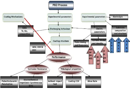
Fig. 3.1 Effects of PEO process parameters on corrosion and tribological properties ….30
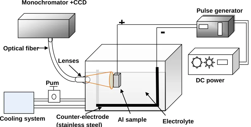
Fig. 3.2 Schematic diagram of the experimental apparatus. ………33
Fig. 3.3 Inclined Impact-sliding Fatigue Test ………37
Chapter 4
Fig. 4.1 Schematic form of the (a) unipolar and (b) bipolar current waveforms, showing
the main controllable parameters of the pulses. ………..…..………40
Fig. 4.2 Typical time variation of the emission line intensity during the PEO process (a)
unipolar current mode and (b) bipolar current mode. ………..…….….…44
Fig. 4.3 Plasma temperature as a function of treatment time (min) determined from the intensity ratio of IMg (3d → 3p) / IMg (4s → 3p), for the samples S1 (at unipolar current mode), and S2-S4 for the bipolar current mode. ………..…45 Fig. 4.4 SEM micrographs showing surface morphology of oxide coating on an Mg AJ62 alloy for: (a) unipolar and (b-c) bipolar current modes. ………47 Fig. 4.5. SEM micrographs using (a) back-scattered electron mode and (b) secondary electron mode of a polished section of coatings on an Mg AJ62 alloy by
means of unipolar (S1) and bipolar (S2-S4) current modes. ………49
XIX
Fig. 4.7. Nyquist diagrams of the EIS tests (a) S1, (b) S2, (c) S3 and (d) S4; the dots represent the experimental data; the solid lines correspond to the simulated
values based on the equivalent circuit model. ………56
Fig. 4.8 The equivalent circuit model for (a) coated and (b) uncoated samples. ………..57
Chapter 5
Fig. 5.1 Schematic representation of the experimental set-up for PEO coatings using (b) single current mode and (b) two current modes (hybrid). ……….….65 Fig. 5.2 Atomic level configuration of H- Balmer series and Mg I. ………67
Fig. 5.3 Plots of anodic voltage vs. treatment time during the PEO process using: (a) unipolar U, (b) bipolar B. (c) hybrid1 H1, and (d) hybrid2 H2 current modes.
………68 Fig. 5.4 Typical emission spectrum using two channels of the spectrometer. ...……70
Fig. 5.5 Typical time variation of the emission line intensity during the PEO process using hybrid current mode, unipolar followed by bipolar. ……….…71 Fig. 5.6 Typical time variation of the emission line intensity during the PEO process
using hybrid current mode, bipolar followed by unipolar. ……….72 Fig. 5.7 Plasma temperature as a function of treatment time (min) determined from the
intensity ratio of (Te1) IH (3d2D → 2p2P) / IH (4d2D → 2p2P) (656.2 nm/486.1 nm) and (Te2) IMg (3s4d 1D→3p1P_1^0) / IMg (3s5d 1D → 3p1P_1^0) (552.8 nm/470.3 nm), for the samples U at unipolar, B at bipolar, H1 and H2 at Hybrid current mode………..…………76 Fig. 5.8 (i) morphology of oxide coatings on an Mg AM60B alloy using secondary electron mode (SE) (ii) SEM micrographs of polished sections of coatings using secondary electron mode (SE) and for: (a, b) unipolar H11, (c, d) hybrid1 (uni + bipolar), (e,f) bipolar H21 and (g , h) hybrid2 (bi + unipolar)
current modes. ………...……….80
Fig. 5.9 Schematic diagram of the discharge model showing the influence of B-type discharges on plasma temperature profile, surface morphology and on the
cross section of the oxide coating. ………82
Fig. 5.10. XRD patterns of (unc. Mg) uncoated and coated samples using (U) unipolar,
(B) bipolar and (H1 and H2) hybrid current modes. ………83
Fig. 5.11 (a) Low and (b) high magnification SEM images and the processed images with corresponding porosities distribution chart for (c) H11, (d) H12, (e) H21 and
(f) H22. ………....……….84
Fig. 5.12 Potentiodynamic polarization curves of the uncoated (S0) and coated samples using unipolar (U), bipolar (B) and Hybrid (H1 and H2) current modes. …..87
XX
Fig. 6.1 The force curve in one impact cycle under Fi/Fc = 325 N/210 N at a 2.5 Hz
impact frequency. ………...……….96
Fig 6.2 (L) SEM micrographs of polished sections of coatings using secondary electron mode (SE) and (R) morphology of oxide coatings on an Mg AM60B alloy using back-scattered electron mode (BSE) for: (a, b) unipolar, (c, d) bipolar and (e, f, g and h) hybrid current modes. ………...………….99 Fig. 6.3 Optical micrographs of the wear tracks after pin-on-disk tests for the uncoated
AM60B Mg alloy (S0), and the coated substrate using unipolar (U), bipolar (B), and the hybrid current modes (H1 and H2). ……….…… 101 Fig. 6.4 Coefficients of friction vs. sliding distance for samples U, B, H1, and H2 and the
S0 uncoated Mg alloy substrate. ……….103
Fig. 6.5 Roughness parameter Rz of the oxide coatings formed using different current
modes and the uncoated Mg alloy substrate. ……….103
Fig. 6.6 Coefficients of friction vs. roughness parameter Rz of the oxide coatings on an
Mg alloy substrate. ………...………104
Fig. 6.7 Wear rates of the oxide coatings formed using different current modes and the uncoated Mg alloy substrate. ………...……….104 Fig. 6.8 (a, d) SEM images of the PEO coating using U current mode, (b, c) EDX
spectrum showing the material transferred from the steel ball to the remaining
coating and (e) illustration of failure modes. ………..………105
Fig. 6.9 Optical micrographs showing the craters (after 2000 impact cycles) of the PEO coatings prepared using (a) unipolar, (b) bipolar, (c) hybrid 1, and (d) hybrid 2
current modes and (e) the uncoated sample. ……….107
Fig. 6.10 (a) SEM images and (b) schematic showing the three layers exposed after
impact testing. ……….………….108
Fig. 6.11 SEM image showing the crater of the PEO U coating with a typical EDX. (a) Line scan EDX from location A to B, (b) backscattered electron image of the crater and (c) area scan of the crater for the Mg, O and Fe. ……….…109
Chapter 7
Fig. 7.1 Plots of anodic and cathodic voltage vs. treatment time during the PEO process
using bipolar current mode. ……….……….117
Fig. 7.2 Typical time variation of the emission line intensity of Mg I during the PEO
process. ………...………..……….117
Fig. 7.3 Typical time variation of the emission line intensity of O I during the PEO
process at three different treatment times. …………..………….…...118
Fig. 7.4 Plasma temperature as a function of treatment time (min) determined from the intensity ratio of Hα (656.3 nm)/Hβ (486.1 nm). …………..………...119 Fig. 7.5 SEM micrographs showing the surface morphology of oxide coatings on AJ62
XXI
Fig. 7.6 SEM micrographs of cross-sections of coatings on AJ62 for different treatment
times. ………..………...….122
Fig. 7.7 Average coating thickness variation with PEO processing time. ……..………123
Fig. 7.8 Inwards and outwards coatings portion during PEO coatings (a), coatings portion
ratios to the total thickness (b) vs. treatment time.…………..……….124
Fig. 7.9 Schematic of the coating process during PEO treatment. ……….125
Fig. 7.10 Schematic diagram of dimension changes of magnesium alloy before and after PEO treatment. ………..….……….128 Fig. 7.11 Diffusion coefficient (D) of O in MgO as a function of treatment time, during
PEO processing of AJ62 Mg alloy. ……….………….130
Chapter 8
Fig. 8.1 Average coating thickness variation with PEO processing time for different Mg alloys (a) and a comparison of the coating thickness from two different
methods (b). ………..….……….…….136
Fig. 8.2 SEM micrographs showing the surface morphology of PEO coated Mg and Mg alloys at different treatment times showing the data of pore analysis
(Percentage area of porosity,%). ……….……….138 Fig. 8.3 SEM plots of coated AJ62 Mg alloy at different treatment time ((a) Nyquist, (b)
Impedance and (c) angles plots). ……….……….140 Fig. 8.4 SEM plots of coated AM60B Mg alloy at different treatment time ((a) Nyquist,
(b) Impedance and (c) angles plots). ……….……….141
Fig. 8.5 SEM plots of coated AZ91D Mg alloy at different treatment time ((a) Nyquist,
(b) Impedance and (c) angles plots). ……….……….142
Fig. 8.6 SEM plots of coated Pure Mg alloy at different treatment time ((a) Nyquist, (b)
Impedance and (c) angles plots). ……….……….143
Fig. 8.7 The equivalent circuit model for (a) coated Mg alloy, (b) coated pure Mg and (b)
uncoated Mg alloys. ……….……….144
Fig. 8.8 SEM plots of uncoated Mg alloys at different treatment time ((a) Nyquist, (b)
Impedance and (c) angles plots). ……….……….151
Chapter 9
Figure 9.1 SEM micrographs showing the surface morphology and cross section of oxide coatings on AZ91D alloy for (a,d) S1(J=0.05 A/cm2) , (b,e) S2(J=0.07 A/cm2) and (c,f) S3(J=0.11 A/cm2) samples respectively. The insert figures
are micrographs at higher magnifications.…………...……….158
Fig. 9.2 Potentiodynamic polarization curves of the uncoated (S0) and PEO-coated samples using different current densities (S1-S3) after three different
XXII
Fig. 9.3 EIS plots of coated and uncoated AZ91DMg alloy at different current densities for 0.5 h immersion time ((a) Nyquist, (b) Impedance and (c) angles plots).
……….……….164 Fig. 9.4 EIS plots of coated and uncoated AZ91DMg alloy at different current densities
for 6 h immersion time ((a) Nyquist, (b) Impedance and (c) angles plots)...166 Fig. 9.5 EIS plots of coated and uncoated AZ91DMg alloy at different current densities
for 24 h immersion time ((a) Nyquist, (b) Impedance and (c) angles plots). ……….……….168 Fig. 9.6 The equivalent circuit model for (a) coated AZ91DMg alloy for 0.5, 6h
immersion time, (b) coated Mg alloy for 24h immersion time and uncoated
Mg alloys. ……….……….169
Chapter 10
Fig. 10.1 PEO process properties, mechanisms and performance ……….176
Fig. 10.2 Plots of anodic voltage vs. treatment time during the PEO process using bipolar current mode: the three discharge stages I, II and III are identified with respect
to sample S2. ………...……….……….179
Fig. 10.3. EDS and SEM micrographs showing the surface morphology and cross section of oxide coatings on AZ91D alloy for different electrolyte concentration and
compositions. ……….……….182
Fig. 10.4 Elements linear scanning analysis of the PEO coating formed in electrolyte containing (a) 0 g/l (Na2WO4) to the base 8g/l Na2Al2O4/KOH electrolyte (b) 0 g/l (Na2WO4) to the 15g/l Na2Al2O4/KOH electrolyte and (c) 6 g/l (Na2WO4) to the base electrolyte by EDX. ……….183 Fig. 10.5 XRD patterns of oxide coatings formed in aluminate-KOH electrolyte with
addition of different concentrations of Na2W04: (a) all samples (b)0 g/l
Na2W04, and (c) 6.0 g/l Na2W04. ……….185
Fig. 10.6 Potentiodynamic polarization curves of the uncoated (S0) and coated samples with (a) different aluminate concentrations (S1 and S5) and (b) different tungstate concentrations (S1 – S4), for 0.33h immersion time. ………187 Fig. 10.7 Polarization resistance (Rp) as a function of coating thickness. ….……...….190
Fig. 10.8 Potentiodynamic polarization curves of the uncoated (S0) for 0.33h and coated samples with (a) two aluminate concentration (S1 and S2) and (b) different tungstate concentrations (S1, S3 and S4). (*) for 24h immersion time...191
Chapter 11
1
CHAPTER 1
INTRODUCTION
1.1Background to this Dissertation
There are many who believe that magnesium is the most exciting engineering material
due to its intrinsic characteristics, particularly its light weight, that make it an attractive
material wherever weight saving is at a premium, including the automotive and aerospace
sectors. The United States federal government has mandated that all automobile
manufacturers increase their vehicle fleet miles per gallon average to 35.5 by 2016 [1].
This will challenge automakers to focus on a new, highly fuel-efficient design and
strongly suggests extensive use of magnesium alloys in construction [2]. In 2011, the
United States Council for Automotive Research (USCAR) proposed a reduction of the
mass of the baseline vehicle by 50% by light weighting, or replacing steel with lighter
materials Al or Mg [3]. USCAR proposed a list of candidates for substitution materials
including: carbon fiber composites, magnesium, aluminum, titanium, metal matrix
composites and advanced high-strength steels. By comparing the cost, the recyclability
and weight reduction of the proposed new materials, magnesium is the most promising
material that fulfills all of the above requirements. This has led to extensive evaluation of
the potential use of magnesium in transportation systems, but up to now substantial
applications have been limited, e.g. in aircraft components [4]. Currently, magnesium
alloys are widely used for automobile components, and are mostly produced by a high
pressure die-casting process. Components made from high pressure die-cast, (HPDC)
magnesium alloy, such as front and support assemblies, steering wheel armatures,
instrument panels and steering column support brackets are playing a vital role in the
automotive industry [5]. Indeed, more and more parts, such as the crank cases, doors,
camshaft sprocket, gearbox housing, several covers, and the arm of an electric generator,
in automobiles have been replaced by magnesium and its alloys [6,7]. But, in fact, many
other applications, including aerospace, electronics, textile machinery, printing machines
[4,8] and bicycle components, can benefit from a switch to lighter materials given the
2
more design engineers are turning to magnesium as an alternative to plastics, composites,
zinc, aluminum, or even steel.
However the limitations of magnesium alloys are primarily their inherently poor
corrosion and low wear resistance. Song and Atrens [9] have concluded that internal
galvanic attack and the instability of the magnesium hydroxide film formed on the
surface of Mg alloys are the two main causes for corrosion of magnesium alloys. There
are generally two possible ways to improve the corrosion behaviour of Mg and Mg
alloys; modify the composition and microstructure, not only through alloying [10] but
also through the development of optimized manufacturing methods and the availability of
suitable raw materials and secondly by surface treatments or form coatings [11], which
produce protective ceramic, polymer or composite layers. In order for a coating to
provide adequate corrosion protection for Mg and Mg alloys, the coating must be
uniform, pore-free, well adhered, and self-healing in case physical damage to the coating
may occur. However Mg alloys low wear resistance, and galling phenomena which
occurs with the counter material, was attributed to their low hardness and to the atomic
structure of their crystals respectively [12]. Generally wear can be reduced by using a
lubricant with appropriate anti-wear additives or surface treating of the alloys to create
hard coating. Recent developments in the plasma electrolytic oxidation (PEO) process
allows for the production of oxide layers on magnesium alloys with excellent tribological
properties, and the potential to be used in many applications [13].
1.2 Objective of this Research
Although a wider picture of the PEO coating growth mechanisms, discharge behaviour
and the fundamental characteristics of PEO processing parameters has become more
clear, a number of challenges still remain concerning the correlation between
processing-structure-properties and performance. This is essential in order to specify the essential
elements that can lead to more reproducible and consistent coatings. A detailed study of
the relationship between PEO processing parameters and the resulting microstructure
properties and, hence, coating performance is required. The present study examines
possible approaches for improving the corrosion and wear resistance of Mg alloys by
3
The objectives of this study were to:
Study plasma/substrate interaction and plasma chemistry using an optical
emission spectroscopy (OES) method and to characterize plasmas in terms
of their electron density and discharge temperature, and their relationships
with the layer formation mechanisms.
Better understand the parameters that influence the discharge phenomena
and their effect on the mechanisms of coating formation.
Study the ceramic coating growth mechanisms in PEO processing
Study the relationships between the alloy composition and microstructure
and the coating microstructure.
Study the interactive effects of PEO process parameters on corrosion and
tribological properties as a general guide to the coatings qualities.
1.3 Organization of the Dissertation
This dissertation is divided into eleven main chapters. Following an introduction in
Chapter 1, a literature review of the PEO coating process, and specific aspects of plasma
electrolytic oxidation of magnesium alloys, is given in Chapter 2. Chapter 3 describes the
materials and experimental details. The influence of current mode on the PEO process
performance and improving the corrosion properties of the coatings on the Mg AJ62
alloy are described in Chapter 4. Chapter 5 describes a study of
processing-microstructure relationships in the PEO coating of AM60B magnesium alloy. A study of
the interactive effects of hybrid current modes on the tribological properties of a PEO
coated AM60B Mg-alloy are presented in Chapter 6. Chapter 7 presents an investigation
of ceramic coating growth mechanisms in PEO processing. In Chapter 8, the effect of
processing parameters and substrate composition on the corrosion resistance of PEO
coated magnesium alloys are presented. Chapter 9 describes the effect of cathodic current
density on the corrosion protection of the oxide coatings formed on AZ91D magnesium
alloy by plasma electrolytic oxidation. The roles of the electrolyte composition and
4
magnesium alloy by PEO process are given in Chapter 10. Chapter 11 summarizes the
results from the present study and offers some suggestions for future work.
References
[1] Aleen M and Javers E, Obama announces new fuel standards. www.politico.com.
May 19, 2009
[2] Brettmann M, Reinhold B, and Schnattinger H, “The use of magnesium in cars –
Aspects of corrosion,” Magnesium Alloys and Their Applications, 2006, ed. K. U. Kainer, (Wiley-VCH, Verlag)
[3] Automotive Materials Partnership LLC (USAMP), Department of Energy (DOE),
Final Report, Projects from January 1, 2002 through January 31, 2011, USAMP REPORT # DOE/OR22910, 2011
[4] Ehrenberger S., Friedrich H. EAssessment of Greenhouse Gas Emissions of
Magnesium Use in Transport. Light Metal Age ( February 2014) 50-53.
[5] Cho K, Sano T, Doherty K, Yen C, Gazonas G, Montgomery J, Moy P, Davis B
and DeLorme R, Magnesium technology and manufacturing for ultra lightweight armored ground vehicles, ARL-RP-236. Aberdeen Proving Ground, MD: Army Research Laboratory; 2009.
[6] Hakamada M, Furuta T, Chino Y, Chen YQ, Kusuda H, Mabuchi M. Life cycle
inventory study on magnesium alloy substitution in vehicles. Energy 32 (2007) 1352-60.
[7] Kulekci M K, Magnesium and its alloys: applications in automotive industry, The
International Journal of Advanced Manufacturing Technology, 39 (2008) 851– 865
[8] Evans G B, “Applications of magnesium in aerospace,” Magnesium Technology,
Proc. London Conf., November 1986, (Institute of Metals, London, (1987), 103-109.
[9] Song G L, Atrens A, Corrosion mechanisms of magnesium alloys, Advanced
Engineering Materials, 1 (1999) 11-33.
[10] Kaesel VT, Tai PT, Bach FW, Haferkamp H, Witte F, Windhagen H. Approach to control the corrosion of magnesium by alloying. In: Proceedings of the Sixth International Conference on Magnesium Alloys and their Applications. New York: Wiley VCH, 2004. p. 534–539.
[11] Gray JE, Luan B. Protective coatings on magnesium and its alloys – a critical review. J Alloys and Compounds 336 (2002) 88–113.
[12] Dobrzanski, L.A., Tanski, T., Cizek, L. and Domagala, J., Mechanical properties and wear resistance of magnesium casting alloys, Journal of Achievements in Materials and Manufacturing Engineering, 31 (2008), 83-90.
5
CHAPTER 2
LITERATURE REVIEW
Published in:
- Hussein R. O., Nie X. and Northwood D. O. (2013), The Application of Plasma
Electrolytic Oxidation (PEO) to the Production of Corrosion Resistant Coatings
on Magnesium Alloys: a Review, Corrosion and Materials 38 (1), pp. 53-63.
- Production of anti-corrosion coatings on light alloys (Al, Mg, Ti) by Plasma
Electrolytic Oxidation (PEO), Riyad O. Hussein, Derek O Northwood, ‘In:
Developments in Corrosion Protection, (M. Aliofkhazraei, Ed.) InTech Open
Publishers, ISBN 980-953-307-1100-2. 2013
2.1. Introduction
There seems to be general agreement that magnesium is a most exciting engineering
material due to its intrinsic characteristics particularly its light weight, that make it an
attractive material wherever weight saving is at a premium, including the automotive and
aerospace sectors. With increasing capacity and falling prices, more and more design
engineers are turning to magnesium as an alternative to plastics, composites, zinc,
aluminum, or even steel. However, the application of magnesium alloys has been limited
by their susceptibility to corrosion and inferior wear performance. Magnesium alloys
exhibit very poor corrosion resistance caused by their chemically active nature, especially
galvanic corrosion, which can further cause severe pitting corrosion on the metal surface
resulting in decreased mechanical stability and an unattractive appearance [1,2]. One of
the major steps in improving the corrosion resistance of magnesium alloys is considered
to be the introduction of high purity alloys [3]. These impurities and intermetallic
compounds “serve as intense local cathodes, driving anodic dissolution” of the
magnesium and hence, reducing the corrosion resistance [4]. The relatively poor wear
performance of magnesium and its alloys is related to a low hardness, magnesium’s high
reactivity and relatively low melting point. The study by Chen and Alpas [5] for AZ91D
6
due to oxidational wear for the mild wear regime and melt wear and severe plastic
deformation wear, for the severe wear regime.
2.2. Coatings for Magnesium Alloys.
So far, a number of theoretical and experimental studies had been performed addressing
different aspects of the corrosion of magnesium alloys. An overview of the different
techniques used for the coatings of Mg and Mg alloys is shown in Fig. 2.1 [6].
Fig. 2.1 Schematic Diagram showing coatings technologies for magnesium alloys
[adapted from [6]].
Generally, coatings can be divided into three classes: conversion coatings, organic and
inorganic deposited coatings. Conversion coatings are produced by chemical or
electrochemical reactions between the substrate and the aqueous solutions to form an
Conversion coating
Chemical conversion (Immersion) Ion implantation
Plasma Electrolytic oxidation
Atmospheric
Inorganic Coatings
Gas-phase deposition process
Electro-plating
Electroless plating
Dipping and Immersio
n
Sputtering
PVD Lase r Plasma spraying
CVD
DLC
Organic/Polymer Coatings
Sol-gel
Painting Spraying
Air- Spraying
Polymer plating
Spin Coating
Dipping and immersion
Anodizing
Chemical conversion (Immersion)
7
oxide layer that simultaneously grows inwards and outwards. Such conversion coatings
represent an effective way to increase the corrosion and wear resistance of magnesium
alloys or, as a pre-treatment, to enhance the adhesion of a final deposited coating [7].
Organic finishing including Sol-gel, painting and powder coating is typically used in the
final stages of coating process. The method most applied to obtain organic coatings is
simple dipping in an organic based solution. Protective coatings can also be produced
from inorganic deposition coatings such as from the gas phase or other physical methods
including plasma spraying, chemical vapor deposition (CVD), Diamond like coating
(DLC) and lasers. Gas phase coatings are inappropriate for applications involving
geometrically complex components. Moreover, physical deposition methods involve high
energy consumption, high costs and complex facilities.
The most common conversion layers are from electrochemical anodization. Recently,
much research has been focused on the selection of electrolytes, including alkaline
solutions with additives of phosphate, silicate, and borate substances [8,9]. However, the
anodizing process sometimes suffers from relatively poor performance for example; the
European Space Agency was having problems with the black anodizing process [10]. A
comparison of the common surface treatments and coatings is given in Table 2.1 [11]. It
is also common to combine two or more techniques for surface coating and/or
modification, in order to obtain properties that are unattainable using an individual
technique.
The PEO process can be considered as a combination of anodizing (electrolytic
oxidation) and plasma discharging processes. The main similarities between the PEO and
anodizing processes are that both of them involve oxidation of the substrate using an
electrolytic bath, and that the first stage of the PEO process is an anodization process.
The PEO process can be distinguished from low voltage anodizing in aqueous solutions
by its operation at electrode potentials greater than the typical breakdown voltages of the
original oxide films (350-600 V) in AC, DC or pulsed AC/DC modes with asymmetric
anodic and cathodic potential peak waveforms, depending on the alloy and electrolyte
composition [12,13]. PEO also operates differently from high energy plasma coating
8
Table 2.1 A comparison of the common surface treatments and coatings for Mg- alloys
[adapted from [11]].
Treatment/coating Drawback (general) Drawback
(environment) Conversion (chromate,
phosphate)
Easily damaged Toxic, particularly
Cr(VI)
Anodizing Sensitive to impurities in the base metal to be coated
Sulphuric acid baths
Organic/polymer Weak mechanical and corrosion resistant properties
Poor recyclability
Gas phase deposition (PVD, CVD)
Thin, porous Chlorine emission
Thermal spray, cold spray
Not suitable for components with complex geometry. Use of more noble materials that can cause corrosion at interface
None
Plasma electrolytic oxidation
Lack of data on coating
performance in practice
None
It has been shown that PEO room temperature technology has a number of unique
advantages: including technological simplicity and the possibility to coat any size and/or
complex structure including welded and riveted joints, and heterogeneous alloys [8].
Pretreatments and post treatments are not strictly necessary for the PEO, except for water
rinses; this reduces environmental concerns with respect to pretreatment and post
treatment solutions. The PEO process is capable of producing uniform and very thick
coatings on the inner and outer surfaces of the substrate materials [14]. One of the main
advantages of the PEO coating is that the oxide coating is integral with the metal
substrate because the coating is a result of substrate oxidation. A comparison between
9
Table 2.2 Comparison of PEO with HA processes.
Process PEO HA
Voltage and current density
High Low
Deposition rate Fast (1~2μm/min) Slow (~0.3μm/min)
Oxidation mechanism Chemical/ electrochemical and plasma chemical
reactions
Chemical/electrochemical reactions
Coating on selected alloys Practical for various kinds of Al, Mg and Ti alloys
Limited (not used for 2000-series alloys, high zinc or silicon Al alloys and Al casting alloys)
Microstructure Amorphous and crystalline phase / Inner dense layer
and outer porous layer
Amorphous / Columnar porous layer and very thin
barrier
Corrosion resistance (Relative)
Excellent (5) Good (1)
Hardness High (~Hv1600) Low (Hv600 max)
Wear resistance (relative) Excellent (30) Fair (2)
Thermal protection Excellent Good
Electrolyte Alkaline solution Acid solution
Dielectric strength Excellent Fair
2.3 PEO Processing
The formation of oxide films on metals using a PEO-like process was first investigated
at the beginning of the twentieth century by Günterschulze and then Günterschulze and
Betz [15]. They published their first studies on the electrolytic spark discharge produced
on an aluminum foil in the early 1930s. In the 1960s and 70s scientists in the former
Soviet Union investigated the anodizing process at potentials of over 200 volts for
developing parts for the submarine sector and for military purposes. This led to plasma
electrolytic oxidation (PEO) technology. The process for depositing an oxide coating on
aluminum using the PEO process was first reported by Markov and co-workers in the
1970s [16,17], and Yerokhin et al [18] identify Markov as the ‘father’ of the PEO
process. Many other researchers worked with the plasma electrolytic oxidation process
throughout the 1980s [19,20]. It wasn’t until the 1990s that the PEO process gained
worldwide recognition as an eco-friendly technology for depositing the tribologically
superior ceramic coatings on aluminum and magnesium alloys [18]. Plasma electrolytic
10
increased attention from both academic institutions and many industries [7,21]. To date,
there are thousands of a scientific publications dealing with a plasma electrolytic
oxidation technology that are distributed in a wide variety of journals and conference
proceedings.
Plasma Electrolyte Oxidation (PEO) is a novel surface engineering technology,
considered as one of the most cost-effective and environmentally friendly ways to
improve the corrosion and wear resistance of magnesium and magnesium alloys [22-23].
A driving force for these developments is the avoidance of expensive equipment required
for competing vacuum-based plasma technologies. The PEO method can be used to form
a thick, hard and adherent ceramic-like coating on the surface of Mg alloys as well as of
lightweight metals (Al and Ti) and their alloys [18]. The substrate is immersed in an
alkaline electrolyte (containing neither the concentrated sulphuric acid nor the chromate
ions used for hard anodizing) and a high potential is applied to it. Different current modes
have been utilized in the PEO treatment including, DC, AC, unipolar and bipolar current
modes [18,24]. The formation mechanisms of the coating layer by PEO are complex due
to the involvement of electro-, thermal-, and plasma- chemical reactions in the electrolyte
[8]. PEO is certainly one of the most promising surface treatments for magnesium and
magnesium alloys since it can provide both corrosion protection, and wear resistance.
The high dielectric strength of the ceramic layers also reduces contact corrosion by
preventing or eliminating the flowing of the current between dissimilar metals.
The effects of the process parameters on the characteristics of the PEO coatings have
been investigated in a number of different studies. Some publications deal with the
influence of the electrolytes which are based on an alkaline solution with additions of
silicates, phosphates and or aluminate [8] where the effect of using a combination of
electrolytes is the production of different cations and anions in the solution which
accordingly influences the resultant coating: see for example the work of Ghasemi et al
[9, 22]. Other studies have examined the effect of current mode [13], current density [25],
process time [26] and the chemical composition of the substrate materials [27].
PEO technology can be applied to coat a variety of materials, such as aluminum,
magnesium, titanium, and zirconium. It can also be applied to alloys that are difficult to
11
silicon content aluminum alloys (2000 series and A380), and magnesium alloys, with the
deposition of layers such as phosphates, silicates and aluminates oxides [18]. This
enables the surfaces of metals such as steel, stainless steel and titanium to be converted
into very hard materials like TiN2, TiB2 or iron carbides.
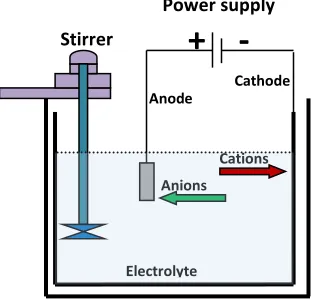
A schematic diagram of the commercial setup for PEO coating shown in Figure 2.2,
where the PEO coating system used to produce the oxide coatings is similar to that used
for electroplating or anodizing. It consists basically of a water-cooled container, with the
alkaline electrolyte, a high anodic potential is applied to it (typically several hundreds of
volts) that trigger numerous micro-discharge events at the metal-electrolyte interface,
generating high instantaneous temperatures and pressures (T > 4000 K [12] and p ~ 100
GPa, [18]). A stainless steel plate in the bath acts as a counter-electrode (cathode) with
the coupons as the anode. Different current modes have been utilized in the PEO
treatments [7,13,28] which play important roles in the consequent voltage breakdown,
local melting and oxidation of the substrate, quenching and re-crystallization processes.
The growth rate, porosity level and microstructure of PEO coatings are significantly
influenced by the current mode. Technically, PEO can be made either by current or
voltage controlled. For the current control, during the coating process, the voltage is
increasing gradually with process time, as the coating thickness increased, so as to
maintain the fixed current density. However, for the voltage control, the current decreases
with process time as the oxide film thickness increased. The optimization of the timing
(frequency), amplitude, and pulse shape of both anodic and cathodic electrical pulses are
essential to achieve controllable, hard, smooth, high growth rates with minimum defect
coatings structure [29].
Fig. 2.2 Schematic diagram of the PEO apparatus.
Cations Anions
Electrolyte Anode
Cathode Stirrer
Power supply
12
During the PEO process different type of discharges will take place [12,29]. An
important consequence of the occurrence of those discharges is the development of
metallurgical processes in the growing oxide layer, which are induced by the heat
liberated in discharge channels from electron avalanches. Because of the local high
temperature and the strong electric field, molten oxide is ejected from the
coating/substrate interface into the coating surface where it is rapidly solidified and
re-crystallized by the electrolyte. Hence, the formation mechanisms for the coatings are
complex due to the involvement of electro-, thermal-, and plasma- chemical reactions in
the electrolyte [12].
The PEO process can be distinguished from low voltage anodizing in aqueous solutions
by its operation at electrode potentials greater than the typical breakdown voltages of the
original oxide films (400-600 V) in AC, DC or pulsed AC/DC modes with asymmetric
anodic and cathodic potential peak waveforms, depending on the alloy and electrolyte
composition [18]. PEO also operates differently from high energy plasma coating under
dry conditions in a controlled gas pressure chamber. It is commonly accepted that the
discharge in PEO occurs when the applied voltage reaches a certain critical value
corresponding to the breakdown of the oxide layer (or at least of the barrier part of it)
formed on the sample surface: this leads to the development of intense light emission
generated at the numerous micro-discharge sites [18].
2.4 PEO coatings for magnesium alloys.
The PEO process involves the creation of plasma discharges around a metal component
immersed in an environmentally friendly electrolyte. The discharge events have a
profound effect on coating microstructure, and hence on the physical and mechanical
properties of the coating [12]. During PEO coating, there are three simultaneous
processes taking place, namely the electrochemical reactions, the plasma chemical
reactions and thermal oxygen diffusion.
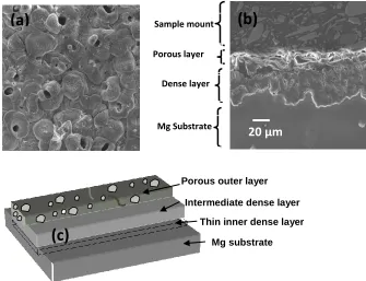
In general PEO coatings on Mg alloys have been found to have a three-layered structure
as shown in Figure 2.3 for an AM60B alloy. Figure 2.3(a) is a SEM micrograph of the
surface of the coating. Figure 2.3(b) is a SEM micrograph of a cross-section of the coated
13
that is relatively dense and a thin inner dense (barrier) layer that is well adhered to the
substrate. Although it is the intermediate dense layer that can provide good mechanical
properties (eg wear) and corrosion protection, it is the inner dense layer that ultimately
provides the best corrosion performance [30].
Examination of the surface morphology of the coatings, Figure 2.3(a), shows pores of
different size: the size reflecting the strength of the discharges that produced the pores.
There are both open and closed pores. The relatively large open pores are concentrated on
the surface of the PEO coatings whereas the closed pores are present in the middle region
of the coating. The surface of the coatings shows a ‘pancake’ structure where the center
of each pancake is a discharge channel through which the molten magnesium surged out
of the channel and was quickly solidified by the relatively cool electrolyte, leaving
distinct boundaries that define each pancake. The uneven melting and sintering effect
causes the formation of a rough surface which could adversely affect the wear
performance through an increase in the coefficient of friction (COF). The channels at the
center of the pancake can penetrate as far as the substrate surface which will degrade the
overall corrosion resistance. Thus, in producing PEO coatings, the elimination, or at least
minimization, of the discharge channels is of primary concern.
Fig. 2.3 SEM micrographs of PEO coating on AM60B alloy showing (a) the surface morphology and (b) cross-section. (c) general schematic.
Intermediate dense layer
Mg substrate Porous outer layer
Thin inner dense layer
(c)
20 µm
(b)
(a)
20 µm
Sample mount
Porous layer
Dense layer
14 2.5 Specific Aspects of Plasma Electrolytic Oxidation Of Magnesium Alloys.
Coating surface morphology, porosity, structure and corrosion behavior of ceramic
coatings on Mg-alloys, are affected by many parameters including, electrolyte
composition and concentration, the substrate composition, and the process parameters
(including current density, current mode, applied voltage, temperature, and treatment
time.
2.5.1 Electrolyte Effects.
The electrolyte chemistry (concentration and composition) is an important parameter
affecting the PEO discharge characteristics and breakdown voltage, and thereby
microstructure, porosity, and thickness of the PEO coatings. Electrolytes typically used in
PEO are environmentally friendly, free of chrome ions, non-corrosive, inexpensive, and
easy to make up and maintain. The PEO coatings on Mg alloys and other lightweight
alloys are normally produced in KOH/NaOH (base electrolyte) with the addition of the
silicate, phosphate, aluminate [28,31-32] which can cause an increase of electrolyte
conductivity and decreases the voltage breakdown. XRD patterns for PEO coatings on
Mg alloys show that the coatings are comprised of amorphous and crystalline phases such
as MgO, Mg2SiO4, Mg3(PO4)2 or MgAl2O4, depending on the electrolyte [22,31]. While
the temperature of the electrolytes should be kept below 40 oC, normally using a water
cooling system, the local plasma temperature in the discharge channels is higher than
4,OOOK, and it is this very high temperature leads to the formation of oxide coatings.
Tungstate, zirconate and permanganate have also been explored as additives in the
electrolytes used to prepare PEO coatings on Mg alloys [33]. An enrichment of the
MgAl2O4 phase in the coating, together with a minimum amount of cubic MgO, has been
shown to improve the corrosion resistance of the coated alloy [34]. MgAl2O4, which is a
spinel phase is also much harder (7.5-8.0 Mohs scale) than MgO (6.0-6.5) or Mg (2.5)
and can provide better wear resistance.
The coatings formed using only KOH at different concentrations, consist of the unstable
and easily corroded MgO phase [25,31]. The phosphate electrolytes and silicate
electrolytes enhance both the corrosion resistance and the hardness of the PEO coatings