ISSN(Online): 2319-8753 ISSN (Print) : 2347-6710
I
nternational
J
ournal of
I
nnovative
R
esearch in
S
cience,
E
ngineering and
T
echnology
(A High Impact Factor, Monthly, Peer Reviewed Journal)
Vol. 5, Issue 2, Februray 2016
Simulation Analysis of the Performance of
Multi Antenna Systems in Ship
Environments
Rofan Xavier X, Sathish S,
PG Scholar, Karpagam College of Engineering, Coimbatore, India
Assistant Professor, Karpagam College of Engineering, Coimbatore, India
ABSTRACT: Below deck environments inthe ship makes the wireless networks a challenging environment. Due to the presents of the metallic constructions in ship environments which reduces the signal transmission and due to coupled sections in ship environments the transmission of electromagnetic signals are reduced which affects the network connections. To avoid these problems Orthogonal frequency-division multi- plexing (OFDM) technique is used with help of multiple-input–multiple-output (MIMO) systems. So the inter symbol interference (ISI) caused by metallic constructions can be reduced. The simulation measurements of the performance of the single and multi antenna OFDM based wireless networks such as maximal ratio combining (MRC) and Alamouti space-time coding are simulated with different below deck environments. The measurements of simulation shows multi antenna system gives more communications reliability and capacity than the single antenna system.
KEYWORDS: Electromagnetic Waves, multiple-input– multiple-output (MIMO), orthogonal frequency-division multiplexing (OFDM).
I. INTRODUCTION
For more than a decade, the wireless networks in the below deck ship is very challenging environment for communication. Because of the presence of Inter symbol interference (ISI) the electromagnetic signals affected during the signal transmission in the below deck environment. And also the presences of coupled sections metallic construction in below deck environment reduce the transmission of the electromagnetic waves.
The literature survey shows that the existing system uses narrowband communication systems which often affected by ISI. The study about existing system gives uses of multi antenna so the signal cannot be often affected by ISI. The multi antenna system can transmit signals from one place to another in both the metallic construction and coupled sections. . The proposed system uses Orthogonal Frequency-Division Multiplexing (OFDM) with multi antenna system.
The OFDM system can improve the channel capacity and channel reliability of the wireless network. This paper evaluates the performance of multi antenna system with single antenna system in the below deck environment. Estimation of the Shannon
channel capacity is done. Determination of signal-to-noise ratio (SNR) are measured. These measurements provides an evidence that multi antenna system can be used to improve network performance over single antenna systems.
II. SYSTEM MODEL
A.SIMO System Model:
ISSN(Online): 2319-8753 ISSN (Print) : 2347-6710
I
nternational
J
ournal of
I
nnovative
R
esearch in
S
cience,
E
ngineering and
T
echnology
(A High Impact Factor, Monthly, Peer Reviewed Journal)
Vol. 5, Issue 2, Februray 2016
antennas are used at the destination (receiver). The antennas are combined to minimize errors and optimize data speed. The source (transmitter) has only one antenna. SIMO is one of several forms of smart antenna technology. SIMO technology has widespread applications in digital television (DTV), wireless local area networks (WLANs), metropolitan area networks (MANs), and mobile communications. The SIMO or Single Input Multiple Output version of MIMO occurs where the transmitter has a single antenna and the receiver has multiple antennas. This is also known as receive diversity. It is often used to enable a receiver system that receives signals from a number of independent sources to combat the effects of fading. It has been used for many years with short wave listening / receiving stations to combat the effects of ionospheric fading and interference. SIMO has the advantage that it is relatively easy to implement although it does have some disadvantages in that the processing is required in the receiver. The use of SIMO may be quite acceptable in many applications, but where the receiver is located in a mobile device such as a cell phone handset, the levels of processing may be limited by size, cost and battery drain.
There are two forms of SIMO that can be used:
Switched diversity SIMO: Thisform of SIMO looks for the strongest signal and switches to that antenna.
Maximum ratio combining SIMO:
This form of SIMO takes both signals and sums them to give the a combination. In this way, the signals from both antennas contribute to the overall signal.
Fig 1: SIMO System Model
B.MIMO System Model:
Where there are more than one antenna at either end of the radio link, this is termed MIMO - Multiple Input Multiple Output. MIMO can be used to provide improvements in both channel robustness as well as channel throughput.
Fig 2: MIMO System Model
ISSN(Online): 2319-8753 ISSN (Print) : 2347-6710
I
nternational
J
ournal of
I
nnovative
R
esearch in
S
cience,
E
ngineering and
T
echnology
(A High Impact Factor, Monthly, Peer Reviewed Journal)
Vol. 5, Issue 2, Februray 2016
III. CAPACITY FOR EACH PHYSICAL
LAYER (ALAMOUTI, SIMO MRC)
A.MultipleInput Multiple Output (MIMO)
Multiple-input multiple-output, or MIMO, is a radio communications technology or RF technology that is being mentioned and used in many new technologies these days. Wi-Fi, LTE; Long Term Evolution, and many other radio, wireless and RF technologies are using the new MIMO wireless technology to provide increased link capacity and spectral efficiency combined with improved link reliability using what were previously seen as interference paths. Even now many there are many MIMO wireless routers on the market, and as this RF technology is becoming more widespread, more MIMO routers and other items of wireless MIMO equipment will be seen.As the technology is complex many engineers are asking what is MIMO and how does it work.
MIMO technology has been developed over many years. Not only did the basic MIMO concepts need to be formulated, but in addition to this, new technologies needed to be developed to enable MIMO to be fully implemented. New levels of processing were needed to allow some of the features of spatial multiplexing as well as to utilise some of the gains of spatial diversity.
Up until the 1990s, spatial diversity was often limited to systems that switched between two antennas or combined the signals to provide the best signal. Also various forms of beam switching were implemented, but in view of the levels of processing involved and the degrees of processing available, the systems were generally relatively limited.
However with the additional levels of processing power that started to become available, it was possible to utilise both spatial diversity and full spatial multiplexing.The initial work on MIMO systems focussed on basic spatial diversity - here the MIMO system was used to limit the degradation caused by multipath propagation. However this was only the first step as system then started to utilise the multipath propagation to advantage, turning the additional signal paths into what might effectively be considered as additional channels to carry additional data.
Alamouti coding Space-time block codes are used for MIMO systems to enable the transmission copies of a data stream across a number of antennas and to exploit the various received versions of the data to improvethe reliability of data-transfer. Space-time coding combines all the copies of the received signal in an optimal way to extract as much information from each of multiple of them as possible.
Space time block coding uses both spatial and temporal diversity and in this way enables significant gains to be made. Space-time coding involves the transmission of multiple copies of the data. This helps to compensate for the channel problems such as fading and thermal noise. Although there is redundancy in the data some copies may arrive less corrupted at the receiver. When using space-time block coding, the data stream is encoded in blocks prior to transmission. These data blocks are then distributed among the multiple antennas (which are spaced apart to decorrelate the transmission paths) and the data is also spaced across time.
A particularly elegant scheme for MIMO coding was developed by Alamouti. The associated codes are often called MIMO Alamouti codes or just Alamouti codes.
ISSN(Online): 2319-8753 ISSN (Print) : 2347-6710
I
nternational
J
ournal of
I
nnovative
R
esearch in
S
cience,
E
ngineering and
T
echnology
(A High Impact Factor, Monthly, Peer Reviewed Journal)
Vol. 5, Issue 2, Februray 2016
impairments in order for the signal to be decoded. The differential space time block codes are normally based upon the more standard space-time block codes. One block-code is transmitted from a set in response to achange in the input signal. This enables the system to work because the differences among the blocks in the set are designed to allow the receiver to extract the data with good reliability.
B.SIMO (Single Input multiple Output)
In conventional wireless communications, a single antenna is used at the source, and another single antenna is used at the destination. In some cases, this gives rise to problems with multipath effects. When an electromagnetic field (EM field) is met with obstructions such as hills, canyons, buildings, and utility wires, the wave fronts are scattered, and thus they take many paths to reach the destination. The late arrival of scattered portions of the signal causes problems such as fading, cut-out (cliff effect), and intermittent reception (picket fencing). In digital communications systems such as wireless Internet, it can cause a reduction in data speed and an increase in the number of errors. The use of two or more antennas at the destination can reduce the trouble caused by multipath wave propagation. An early form of SIMO, known as diversity reception, has been used by military, commercial, amateur, and shortwave radio operators at frequencies below 30 MHz since the First World War.
Maximal Ratio Combining (MRC)
Various techniques are known to combine the signals from multiple diversity branches. In Maximum Ratio combining each signal branch is multiplied by a weight factor that is proportional to the signal amplitude. That is, branches with strong signal are further amplified, while weak signals are attenuated. MRC is the optimum diversity combining method for an AWGN LTI channel. After MRC of i.i.d Rayleigh-fading signals, the received signal exhibits Nakagami fading, with a gamma distribution. This allows relative simple mathematical evaluation of for instance outage probabilities. The idea to boost the strong signal components and attenuate the weak (relatively noisy) components, as performed in MRC diversity, is exactly the same as the type of filtering and signal weighting used in the matched filter receiver. A particularly interesting application of this concept is the Rake receiver for detecting direct- sequence CDMA signals over a dispersive channel.
IV. EXPERIMENTAL SETUP
A. Wireless System
ISSN(Online): 2319-8753 ISSN (Print) : 2347-6710
I
nternational
J
ournal of
I
nnovative
R
esearch in
S
cience,
E
ngineering and
T
echnology
(A High Impact Factor, Monthly, Peer Reviewed Journal)
Vol. 5, Issue 2, Februray 2016
B. Performance Metrics
For the estimation of the performance of the OFDM systems with MIMO techniques can be done using Shannon channel capacity. because the Shannon channel capacity gives data transmission with less bit error and transmission from the one antenna to another antenna is measured in bps/Hz. For a flat fading the channel capacity is defined as
Where PTx is transmit power, h is the complex channel gain, and N 0 is the noise power in the channel.
Fig. 3: Below deck ship environment.
ISSN(Online): 2319-8753 ISSN (Print) : 2347-6710
I
nternational
J
ournal of
I
nnovative
R
esearch in
S
cience,
E
ngineering and
T
echnology
(A High Impact Factor, Monthly, Peer Reviewed Journal)
Vol. 5, Issue 2, Februray 2016
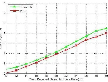
V. SIMULATION SCENARIOS
The simulation analysis of the 1*2 single input and multiple input Maximal-ratio combining and 2*2 Alamouti space-time coding are taken in the below-deck environment with the metallic construction and the coupled sections. The channel capacity of each physical layers of both the antenna transmitter and receiver are simulated using MATLAB software.
VI. CONCLUSION
Simulation analysis results gives that the multi antenna system can improve communications performance over single antenna system in a below-deck environment and in other metallic constructions and coupled sections. MIMO system should be used in the below deck environments over SIMO system. Determination of Shannon channel capacity gives multi antenna techniques can improve communications reliability and capacity. Thus, multi antenna systems can be used in below deck ship environments over single antenna systems.
REFERENCES
[1] E. Mokole, M. Parent, T. Street, and E. Tomas, “RF propagation on ex-USS Shadwell,” in Proc. IEEE-APS Conf. Antennas Propag. Wireless Commun., 2000,pp. 153–156.
[2] D. Estes, T. Welch, A. Sarkady, and H. Whitesel, “Shipboard radio frequency propagation measurements for wireless networks,” in Proc. Military Commun.Conf., 2001, vol. 1, pp. 247–251.
[3] X. H. Mao, Y. H. Lee, and B. C.Ng, “Wideband channel characterization along a lift shaft on board a ship,” in Proc. IEEEAntennas Propag. Soc. Int. Symp., Jul. 2010,pp. 1–4.
[4] X. H. Mao, Y. H. Lee, and B. C. Ng, “Study of propagation over two ends of a vessel in VHF band,” in Proc. Asia-PacificMicrow. Conf., Dec. 2010, pp. 1946–1949.
[5] A. Mariscotti, M. Sassi, A. Qualizza, and M. Lenardon, “On the propagation of wireless signals on board ships,” in Proc.IEEE Instrum. Meas. Technol. Conf., May2010, pp. 1418–1423.
[6] T. Bronez and J. Marshall, “Shipboard experiments for a multihop 802.11 communications system-RF channel characterization andMAC performance measurement,” in Proc. Military Commun.Conf., Oct. 2005, vol. 1, pp. 557–563.
[7] R. Heath and A. Paulraj, “Switching between diversity and multiplexing in MIMO systems,” IEEE Trans. Commun., vol. 53, no. 6, pp. 962– 968, Jun. 2005.
[8] Rice University, Houston, TX, USA,
[9] “Rice UniversityWARP Project,” [Online]. Available: http://warp.rice.edu
10] A. Goldsmith, WirelessCommunications. New York, NY, USA:Cambridge Univ. Press, 2005.
[10] S. Loyka and G. Levin, “On physically-based normalization of MIMO channel matrices,” IEEE Trans. Wireless Commun., vol. 8, no. 3, pp. 1107–1112, Mar. 2009.
[11] R. Shafik, S. Rahman, R. Islam, and N. Ashraf, “On the error vector magnitude as a performancemetric and comparative analysis,” in Proc. Int. Conf. EmergingTechnol., Nov. 2006, pp. 27–31.
[12] D. Love, R. Heath, V. Lau, D. Gesbert, B. Rao, and M. Andrews, “An overview of limited feedback in wireless communication systems,”