Abstract: Multiple Input Multiple Output (MIMO) systems are used to assure high spectral efficiency, huge data rate, improved channel capacity and low error rates. Forward error correction coding is required in communication systems for the efficient transmission of data. One of such code is Low-Density Parity-Check codes. Block Diagonalization is used as a precoding technique which reduces Multi-User Interference and Space-Time Block Codes decreases the signal fading effects. The combination of both can effectively mitigate channel impairments. Hence, for the MIMO systems, we have proposed a technique which is Low-Density Parity-Check codes aided Block Diagonalization using Space-Time Block Codes by assuming that the channel state information is known. Low-Density Parity-Check codes provide efficient coding when compared with the other encoding techniques even in rank deficient scenarios.
Index Terms: Binary Phase Shift Keying (BPSK), Block Diagonalization (BD), Inter Symbol Interference (ISI), Low-Density Parity-Check (LDPC) codes, Minimum Mean Square Error (MMSE), Multi-User Interference (MUI), Signal to Noise Ratio (SNR), Quadrature Phase Shift Keying (QPSK), Quadrature Amplitude Modulation (QAM), Singular Value Decomposition (SVD), Space Time Block Codes (STBCs), Trellis Coded Modulation (TCM) and Zero Forcing (ZF)
I. INTRODUCTION
Wireless Communications (in particular mobile communications) are spread extensively due to their enormous usage. MIMO systems with the help of various diversity techniques are used to maintain the expanding data rate by providing high spectral efficiency. MIMO systems are used to ensure tremendous increase in speed of transmission with least possible degradation in Quality of Service [1], [2], [3]. The idea of numerous antennas instead of single antenna is justified to be successful for the enhancement of bit rate, security, coverage and overall performance of communication systems. By using MIMO systems, channel capacity is increased because total antennas used are directly comparable with the channel capacity. Implementing Spatial
Revised Manuscript Received on April 17, 2019
M. Jhansi Madhuri, BE student, Dept. of Electronics and Communication Engineering, SRKR Engineering College, Andhra Pradesh, India
Buddaraju Revathi, Assistant Professor, Department of Electronics and Communication Engineering, SRKR Engineering College, Bhimavaram, Andhra Pradesh, India
M. Yaswanthi, BE student, Dept. of Electronics and Communication Engineering, SRKR Engineering College, Andhra Pradesh, India
Diversity scheme in MIMO results in the increase of link reliability and reduces Bit Error Rate (BER) [4].
Some of the challenging issues which are to be considered in designing of MIMO systems are Multi-User Interference and signal fading effects. By taking these challenges into consideration we have proposed this technique. MUI can be reduced by Block Diagonalization technique by making the efficient use of the channel matrix.
LDPC codes are one of the best channel encoding/decoding codes and which are capable of data transmission with greater efficiency. Extensively used in Space Communications due to their channel impending capabilities [5]. The outstanding performance of these codes is due to the decoding algorithms which consumes huge amount of memories [6].
Block Diagonalization technique is mainly based on SVD technique and Water Filling algorithm [7].
SVD technique decomposes a single matrix to three matrices [8]. This technique is also known as factor analysis. Applying SVD technique to matrix B, it can be decomposed as
(1.1)
where, B represents p × q matrix,
U represents p × q left-hand unitary matrix,
S represents q × q diagonal matrix containing singular values of matrix B,
V represents q × q right-hand unitary matrix.
Water Filling algorithm [9], [10] helps in raising the power to the required level. It can be used in wireless communication such that we can overcome the transmission losses which are ensued, as the power level of the transmitted signal is raised. Hence, by increasing the power level we can able to retrieve the original signal.
In STBCs we will transmit copies of data to reduce signal fading effects [11], [12]. This is done by transmitting the same information twice in two time slots. Then even if the signal in one time slot is corrupted with more noise at a singular instant of time we may able to retrieve the signal from the second time slot as it may not be effected with that much of noise at that particular instant of time. Hence, by reducing signal fading effects we may able to retrieve the original signal.
At the receiver side, ZF and MMSE detectors are generally used for retrieving the information from the signal received at the receiver antenna.
ISI can be removed by a Zero Forcing detector. Its performance is ideal in the
Performance Analysis of Low-Density
Parity-Check Codes Aided Block
Diagonalization using Space Time Block Codes
for MIMO Systems
noiseless channel. But, if it is a noisy channel then it will amplify the noise to a great amount at the frequencies where the channel response has less magnitude.
ZF estimates the transmitted bits using [13], [14]
(1.2)
where, H represents channel matrix
for 2×2 MIMO systems,
represents Hermitian of the channel matrix,
D represents received bits after the addition of noise at the receiver side,
represents estimated transmitted bits by ZF method.
As ZF equalizer provides noise amplification for lesser channel response, a more balanced equalizer used in this case is Minimum Mean Square Error equalizer. Unlike ZF equalizer it doesn’t eliminate ISI. But, the total power of the noise and ISI components present in the output are minimized.
MMSE retrieves bits by using [15]
(1.3)
where, H represents Channel Matrix,
for 2×2 MIMO systems,
HH represents Hermitian matrix of the channel matrix, σ2 represents variance,
I represents Identity Matrix, D represents received signal matrix,
represents estimated transmitted bits by MMSE method
II. SYSTEMMODEL
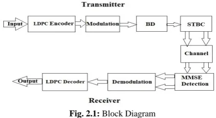
[image:2.595.53.275.496.617.2]The block diagram shown in fig 2.1 represents the transmission of data from transmitter to receiver
Fig. 2.1: Block Diagram
A. Transmitter
At the transmitter, initially we generate data randomly by the source and the generated data is fed to LDPC encoder. LDPC Encoder does two tasks, which are, creation of LDPC matrix and generation of parity bits.
Creation of LDPC matrix:
There are two methods for distributing a non-zero element. One method is by placing 1’s uniformly at random along each column and the other is by placing 1’s uniformly at random along each column and row.
Try to eliminate girth-4 because of looping problems. Create full sparse matrix T by employing one of the above methods.
The created matrix will be of size M×N where, M represents the number of parity check bits and N represents the block length. Hence, R=1/2 LDPC matrix is created.
Generation of Parity bits:
Using sparse matrix properties of T and sparse LU decomposition parity bits are computed. Let T= [D|E]. Now, we have to decompose D to LU where, L represents Lower triangular matrix and U represents Upper triangular matrix. To decompose the matrix D, it must be non-singular. Hence 1’s must be reordered diagonally. Thereby we get parity-check bits and the reordered sparse matrix G, which is used for encoding and decoding instead of original sparse matrix T.
We can use any of the modulation schemes such as BPSK, QPSK, QAM, and so on. Here, we have used BPSK modulation and applied modulation scheme to the LDPC encoded bits.
To the modulated bits, apply Block Diagonalization technique which is a combination of SVD technique and Water Filling algorithm [7].
SVD technique:
SVD is performed on the channel matrix such that channel matrix H can be decomposed into S, V, D matrices [8].
(2.1) where, H is channel matrix and is equal to
, A and C are unitary matrices,
B is a diagonal matrix. Apply Water Filling algorithm. Water Filling Algorithm: [9], [10]
1.Consider absolute value of noise vector at different frequencies in linear units. Noise vector must be a row vector. 2.Also consider power constraint and acceptable tolerance in the same units of noise vector.
3.Initial water level should be considered in the units of noise vector such that
abs (Power Constraint -SUM(MAX(Initial Water Level – Noise Vector, 0))) <= Acceptable Tolerance
4.Build it in such a way that
Power Constraint >= SUM (MAX (Initial Water level, 0)) and it should be never less than SUM (MAX (Initial Water level, 0)
Modulated bits are multiplied with Vector C, Power Constraint and then transmitted through the channel using Space time block codes.
STBCs means transmitting copies of data i.e., in the first time slot the information will be transmitted as and in the second time slot transmit the information as . Here, and are the data bits which are obtained after the multiplication of C, power constraint with modulated bits [10], [11]. As we are transmitting copies of data, we can recover the original signal, thereby reducing signal fading effects.
Algorithm at transmitter:
By a random source generate a stream of data. Create an LDPC matrix.
Generate parity check bits. These two steps constitute LDPC encoder and we get
Apply the modulation technique to the encoded bits. By considering channel state information is known, apply
the Singular Value Decomposition technique to the channel matrix.
Apply Water Filling algorithm. These two steps constitute Block Diagonalization technique.
Multiply the data with a unitary matrix obtained from SVD technique and Power Constraint obtained from Water Filling algorithm.
Transmit the modified data through the channel with the help of STBCs.
B. Receiver
At the receiver antenna, bits received in two time slots are as follows:
(2.2)
(2.3)
where, H is the channel matrix,
P1 and P2 represents the input bits to the channel of size Nt × b in first and second time slots respectively,
Here, Nt represents number of transmitter antennas and b represents number of bits after modulation.
N1 and N2 represents receiver noise matrices in time slots 1 and 2 respectively and are of size Nt × b.
As the first step at receiver, apply MMSE detection to the received bits. It is performed by [15]
(2.4)
(2.5)
Here, , H is the Channel Matrix,
C is right hand unitary matrix obtained from SVD technique, σ2 is the variance,
I is the Identity Matrix,
and are the matrices obtained from equations (2.2) and (2.3) respectively,
and are the bits estimated in first time slot and second time slot respectively.
For the obtained output matrices (Z1 and Z2) perform the corresponding demodulation according to the modulation scheme applied.
For the demodulated bits apply LDPC decoding based on Sum-Product Algorithm (SPA). There are 4 versions of SPA decoder which are
Hard-Decision decoder – It is also known as Bit-Flip decoder. It decodes 1/0 message as follows. If the majority of bits present is 1 then it chooses ‘1’ or else '0'. The decoder could be used for introduction to message passing algorithms since it does not employ complicated probability. Expect worse performance compared for very low Eb/N0.
Probability-Domain SPA decoder – Based on Gallager’s
work
Log-Domain SPA decoder –Similar to probability-domain SPA, but instead of probability function, use log-likelihood. Advantage is that operations can be performed using additions instead of multiplications, which takes less computational time.
Simplified Log-Domain SPA decoder – It is similar to Log-Domain SPA decoder, but log-likelihood function is directly replaced by incoming signal waveform. Hence simplified log-domain SPA decoder doesn’t need noise variance information.
Here, we used Log-Domain SPA decoder and performed decoding process.
After the decoding process, calculate BER. Performance of the proposed technique is obtained by repeating the above steps with various SNR.
III. RESULTS
[image:3.595.315.534.58.261.2]By assuming that we have channel state information and by creating random LDPC codes, results are obtained as follows:
Fig -3.1: Performance comparison of MMSE and ZF detectors for 2×2 MIMO systems
From fig-3.1 we observe that at 6dB SNR, BER for ZF is 2×10⁻¹ and BER for MMSE
is 6×10⁻³. From the graph we
performance of MMSE is better than ZF as it has less BER when compared with ZF. Hence, we use MMSE detection technique instead of ZF detection technique.
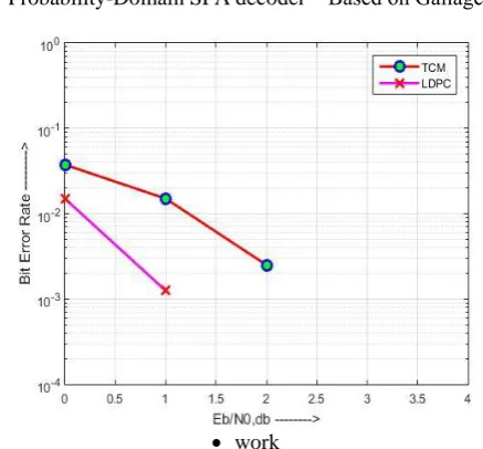
Fig -3.2: Performance comparison of TCM and LDPC codes for 2×2 MIMO systems
[image:4.595.59.283.186.415.2]From fig-3.2 we observe that at 1dB SNR, BER for TCM encoded MMSE is nearly 10--2 and for LDPC encoded MMSE is nearly 10-3. Hence, we conclude that LDPC performance is superior to TCM. So, LDPC codes are encoded to Block Diagonalization technique.
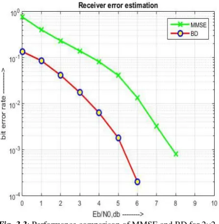
Fig -3.3: Performance comparison of MMSE and BD for 2×2 MIMO systems
[image:4.595.54.285.497.695.2]From fig-3.3 we observe that at 2dB SNR, BER for MMSE is 2×10⁻¹ and for BD is 4×10⁻². So, from the graph we conclude that performance of BD is better than MMSE technique. Hence, we applied LDPC encoding to Block Diagonalization technique.
Fig -3.4: Performance comparison of BD with and without LDPC codes for 2×2 MIMO systems
From fig-3.4, we observe that at 2dB SNR, BER for Block Diagonalization technique without any encoding schemes is 5×10⁻² and for LDPC encoded Block Diagonalization technique is nearly 2×10⁻³. Hence, LDPC encoded Block
Diagonalization technique is superior to BD technique in performance.
Fig -3.5: Performance comparison of BD-STBC with and without LDPC encoding for 2×1 MIMO systems
From fig-3.5, we observe that performance of
LDPC-BD-STBC is superior to BD-STBC because of the application of LDPC encoding. At 1dB BER for
LDPC-BD-STBC is 10-2 and for BD-STBC is 7×10⁻³. BD-STBC technique works well in Rank Deficient scenario and by the application of LDPC encoding its performance is improved even better. Hence, our proposed technique works well in practical Rank Deficient scenario also where, most of the receivers fail.
IV. CONCLUSION
LDPC is an efficient encoding technique when compared with TCM, BD reduces the effect of MUI and STBCs reduces signal fading effects. In this paper, we proposed LDPC aided Block Diagonalization technique using STBCs (LDPC-BD-STBCs) which works better in rank deficient scenarios when compared to TCM-BD-STBCs.
REFERENCES
1. W.SONONE,N.B.CHOPADE ,“TECHNIQUES FOR IMPROVING BER AND
SNR IN MIMO ANTENNA FOR OPTIMUM PERFORMANCE ,” SSRG
INTERNATIONAL JOURNAL OF ELECTRICAL AND ELECTRONICS
ENGINEERING (SSRGIJEEE), VOL.1, NO.3,MAY 2014.
2. E. Ghayoula, A. Bouallegue, R. Ghayoula and J.-Y. Chouinard, “Capacity and Performance of MIMO systems for Wireless Communications,” Journal of Engineering Science and Technology Review, vol. 7, no. 3, pp. 108–111, August 2014.
3. S. Sarkar, M. S. Rahman, “Optimal BER in MIMO Rayleigh fading channel from QPSK Modulation: Modified MMSE Versus ML Equalizer Evaluation,” International Journal of Electronics and Informatics, vol. 2, no. 1, pp. 34–39, March 2013.M. Young, The Technical Writer’s Handbook. Mill Valley, CA: University Science, 1989.
4. Y. Jiang, J. Li, and W. Hager, “Uniform channel decomposition for MIMO communications,” IEEE .Signal processing., vol. 53, pp. 4283-4294, Nov.2005
5. K. S. Andrews, D. Divsalar, S. Dolinar, J. Hamkins, C. R. Jones, and F. Pollara, “The development of turbo and LDPC codes for deep-space applications,” Proceedings of the IEEE, vol. 95, no. 11, pp. 2142–2156, 2007.
6. Q. Huang, Q. Xiao, L. Quan, Z. Wang, and S. Wang, “Trimming soft-input soft-output viterbi algorithms,” IEEE Transactions on Communications, vol. 64, no. 7, pp. 2952–2960, 2016.
7. Md Hashem Ali Khan, K M Cho, Moon Ho Lee and JinGyun Chung, “A simple block diagonal precoding for multi-user MIMO broadcast channels” Khan et al. EURASIP Journal on Wireless Communications and Networking 2014, 2014:95
8. Buddaraju Revathi, Mahadasa Jhansi Madhuri, Manthena Yaswanthi, Gudipati Maheswari, Marni Satya Srinivas, “Performance Analysis of TCM aided Block Diagonalization using STBCs for MIMO systems”, International Conference on Smart Systems and Inventive Technology (ICSSIT 2018) December 13-14, 2018.
9. Z. Pan, K.-K.Wong, and T.-S. Ng, “Generalized multiuser orthogonal space-division multiplexing,” IEEE Trans. Wireless Commun., vol. 3, no. 6, pp. 1969-1973, Nov. 2004.
10. GH Golub, CF Van Load, Matrix Computations, 3rd edn. (The John Hopkisns University Press, Baltimore and London, 1996)
11. S.M.Alamouti, “A simple transmit diversity technique for wireless communications”, IEEE jsac, Vol No .16, pp.1451-1458, October 1998. 12. B.Revathi, P.S.Samhitha, S.V.V Lavanya, G. Amani, N.A Manikantha,
“ BER analysis of TCM aided STBC in MIMO-OFDM Systems” ,International Conference on Electrical, Electronics, Signals, Communication and Optimization (EESCO), 2015
13. W Li, M Latva-aho, “An efficient channel block diagonalization method for generalized zero forcing assisted MIMO broadcasting systems”. IEEE Trans on Wireless Commun 10(3), 739–744 (2011)
14. Tanvir Ahmed, Nezam Uddin, Motiur Rahaman, “Performance Analysis of Zero Forcing Equalizer in 2×2 and 3×3 MIMO Wireless Channel”, Global Journal of Researches in Engineering (F) Volume XIV Issue IX Version I Year 2014.