Design of Bidirectional Converter Using Fuzzy
Logic Controller to Optimize Battery
Performance in Electric Vehicle
Sasikumar S1, Krishnamoorthi K2, Soniya N3
Research Scholar, Department of Electrical Engineering, Sona College of Technology, Salem, India 1
Associate Professor, Department of Electrical Engineering, Sona College of Technology, Salem, India 2
PG Scholar, Department of Electrical Engineering, Sona College of Technology, Salem, India3
ABSTRACT— Hybrid Electric Vehicle (HEV) is an electric vehicle which has more than one energy source. HEV is powered by battery, photovoltaic (PV), or fuel cell. It needs boost converter linked by bidirectional converter to achieve maximum power output. Maximum power point is achieved by setting reference power to manage bidirectional converter duty cycle. This paper shows design of HEV using PV and battery controlled by fuzzy logic controller. Bidirectional converter is used to adjust the charging current and discharging current of the battery. Regulation of the current is aimed to prevent damage to the battery, and reduces gassing phenomena that occurs in lead-acid batteries. Fuzzy logic controller is designed to optimize battery lifetime and used capacity. Simulation result shows that bidirectional converter has 90 percents efficiency and can regulate the charging current and discharging current. The bidirectional converter also can maintain the output voltage constantly.
KEYWORDS: Bidirectional DC-DC converter, HEV, PV with Coupled Inductor.
I. INTRODUCTION
Battery is an important part in modern electrical system, including application for hybrid power systems [1] and electric vehicle systems. The developments of battery management systems [2], the use of better inverter control [3], the use of efficient dc converter [4] are known to improve the battery performance and lifetime. HEV driving cycle (acceleration, braking, maintaining to a constant velocity) needs a bidirectional converter to manage Battery charging and discharging. Bidirectional converter will manage the DC link voltage constant. Charging and discharging processes would make voltage of battery changed. The battery voltage change can make a gassing effect that can reduce the lifetime of battery. This study is taken to achieve maximum power in PV, so it not only can receive maximum power of PV, but also can reduce the dimension and weight of HEV. This method is expected to be an alternative method to increase HEV Performance, so the usage of HEV would be increased in the future. The aim of this research is to design a battery charging and discharging system using bidirectional converter with coupled inductor that optimized by Fuzzy Logic Controller.
II. ELECTRIC VEHICLE SYSTEM
charge and discharge current. Bidirectional converter system with coupled inductor is more efficient than common bidirectional converter [5].
A. PHOTOVOLTAIC MODELING
PV is used as the main source of the system. PV is Modeled as an equivalent series as shown in Fig.2. Rsh and Rsis intrinsic resistance; they are arranged in parallel connection and serial connection. Rsh value is very high and Rs value is very low. Both variables are neglected in the analysis process. PV cells which is arranged to bigger units called PV modules.These modules are connected in parallel and serial to make PV arrays [7].
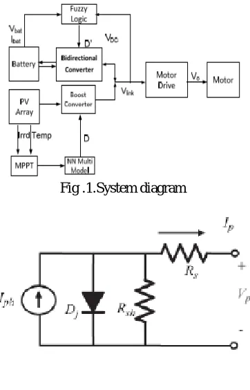
Fig .1.System diagram
Fig.2.Equivalent circuit of PV
Mathematic model of PV arrays is presented below:
(1)
I is output current of PV module (Ampere), V is output voltage from PV module, and Io is saturated current of PV. Vt= NskT/q is thermal voltage of PV, and Ns is connected in serial connection.
B. BATTERY MODELING
The battery used in this study is the kind of Lead-Acid. Equivalent circuit of the battery is shown in Fig.3. The circuit consists of an internal resistance, controlled voltage source, with f1 and f2 is a function of charge and discharge. For lead acid batteries charge and discharge functions are as follows [8]:
(3)
Ibatt is the current flowing through the battery. SOC that the battery can be written by the following equation:
Battery thermal modeling is obtained by performing an experiment. From experiments obtained mathematical model of thermal battery is:
T is temperature, C is battery capacity in Ah, and h is operating time.
Fig.3.Equivalent circuit of lead -acid battery
Fig.4.Topology of Bidirectional Converter with coupled inductor
C. BIDIRECTIONAL CONVERTER MODELING
(4)
VDC is the DC bus voltage and IDC is the current flowing to the inverter. Value of the output voltage of Bidirectional Converter should be equal to the DC bus voltage. The output voltage on Bidirectional Converter can be set using this equation [5]:
(5)
D is the duty cycle of the switches S1 and S2. Bidirectional converter is connected to the battery, and the converter works in two modes: When the battery is in Boost mode, equation (4) can be applied. When the battery is in Buck mode, equation changes to [5]:
(6)
D. BIDIRECTIONAL CONVERTER CONTROL DESIGN
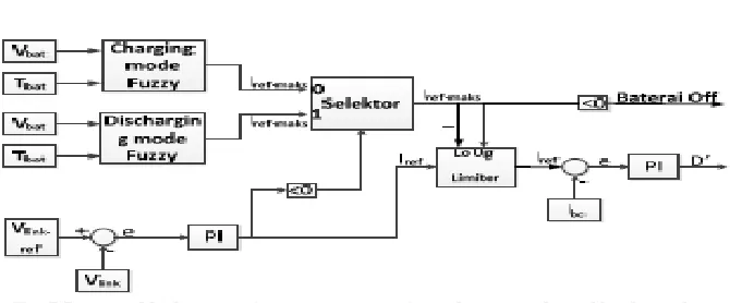
Scheme of the main converter system control circuit that proposed is shown in Fig.5. Converter control circuit is divided into 2 parts: controls the bidirectional converter in charging mode, and controls the bidirectional converter in discharging mode. The combination of control used by the converter depends on the operating conditions of the system as shown in Table I and Table II.
Fig.5.Proposed bidirectional converter control for boost mode and buck mode.
Fig.6.Membership function input fuzzy logic controller.
III. SIMULATION AND RESULTS
Bidirectional converter is used as a regulator of charging and discharging of the battery. Charging / discharging should not exceed the limits of charging / discharging, and a stable DC voltage link.
Fig.8.Battery charging current (a) DC link voltage (b)
A. SIMULATION RESULT IN LOAD CHANGES
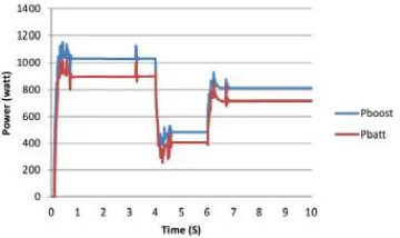
shows that the voltage is maintained at 600 Volts. It shows that the bidirectional converter as a voltage regulator was able to regulate the flow of power so that the voltage becomes stable.
Fig.9.Battery power and bidirectional input power.
Fig.10.The process of change in boost mode charge into trickle charge.(a) Battery current,(b) Voltage DC link,(c) PV power,(d) The battery voltage
III. CONCLUSION
battery current change of mode boost charge into trickle charge. Fig. 10 (b) presents the DC link voltage. DC link voltage momentarily increased when there is a change charging mode. However, as the operation of the controller in the PV power down, the voltage stabilizes at a value of 620 Volts. PV power reduction can be observed in Fig.10. (c). The controller responds excess PV power by reducing the power output of PV. Thus the DC link voltage can still be maintained despite the PV power exceeds the power charging.
REFERENCES
[1]. Amalin Rishma, A., Raja Rajeswari, P. and Sasikumar, M. (2012), “High Efficiency Modified Pulse Width Modulation Bidirectional Converters for Medium Power Drives,”IJAIEM, vol. 1, no. 2, pp. 94–100.
[2].Amin Mirzaei, Awang jusoh and Zainal Salam, (2012), “Design and Implementation of High Efficiency Non Isolated Bidirectional Zero Voltage Transition Pulse With modulated DC-DC converters,” Elsevier,Energy 47, pp. 358–369.
[3]. Baburaja.C and Jayakumar, J., (2013) “Transformer less soft switching bi-directional DC-DC Chopper”,International journal of Engineering and Advanced Technology, vol. 2, pp.391-395.
[4]. Chuan-Kuei Huang, Hsiau-Hsian Nien,Koan-Yuh Chang and Wen-Jer Chang, (2010) “An Optimal Designed RCD Snubber for DC-DC Converters,”Journal of Marine Science and Technology, Vol. 18, No. 6, pp. 901-906.
[5]. Lee, D.Y., Kee, M. K., Hyun, D.-S. and Choy, I., (2003) “New zero-current-transition PWM DC/DC converters without Current Stress,” IEEE Trans. Power Electron., vol. 18, no. 1, pp. 95–104.
[6]. Doo-Yong Jung, Sun-Hee Hwang, Young-Hyok Ji, Jung-Hyo Lee, Yong-Chae Jung and Chung-Yuen Won, (2013) “Soft-Switching Bidirectional dc-dc Converter with a LC Series Resonant Circuit,” IEEE Trans.Power Electron ,vol. 28, no. 4, pp. 1680– 1690.
[7]. Hua, G., Leu, C., Jiang, Y. and Lee, F. C. ,(1994), “Novel zero-voltage transition PWM converters,” IEEE Trans.Power Electron., vol. 9, no. 2, pp. 213– 219.
[8]. Ho-Sung Kim, Myung-Hyo Ryu,Ju-Won Back and Jee-Hoon Jung, (2013) “High-Efficiency Isolated Bidirectional AC-DC Converter for a dc Distribution System,” IEEE Trans.Power Electron., vol. 28, no. 4, pp.1642–1654.
[9]. Hua Han, Yonglu Liu, Yao Sun,Hui Wang and Mei Su, (2014), “A Single Phase Current Source Bidirectional Converter for V2G Applications” Journal of Power Electronics, vol. 14, no. 3, pp. 458-467.
[10].Huiqing Wen and BinSu, (2015), “Reactive Power and Soft-Switching Capability Analysis of Dual -Active –Bridge DC-DC Converters with Dual-Phase-Shift Control” Journal of Power Electronics, vol. 15, no. 1, pp.18–30.
[11].Hyung-Min Ryu , (2014) “High Efficient High-Volatge MOSFET Converter with Bidirectional Power Flow Legs” ,Journal of Power Electronics, Vol. 14, No. 2, pp. 265-270.