DWT and DCT based Robust Iris Feature
Extraction and Recognition Algorithm for
Biometric Personal Identification
Sunita V. Dhavale
Defence Institute of AdvancedTechnology, Girinagar, Pune-411025, INDIA.
ABSTRACT
Human iris is one of the most reliable biometric because of its uniqueness, stability and noninvasive nature. Thus it has attracted the attention of biometrics based identification and verification research and development community. In this paper, a new approach of iris image feature extraction technique based on the statistical properties of Discrete Cosine Transform (DCT) domain is proposed. A Canny Edge Detection followed by Hough Transform is used to detect the iris boundaries in the eye’s digital image. The two level Discrete Wavelet Transformation (DWT) is applied on the segmented and normalized iris region. Both second level horizontal and vertical detail sub-bands are used for encoding unique iris feature. Each of those frequency sub-bands is divided into 8x8 non-overlapping blocks and DCT is applied to each block. Unique iris features are obtained by comparing the energies containing in corresponding DCT blocks of both the sub-bands. These features extracted are used to generate unique encoded binary image and corresponding unique binary bit stream/code is constructed. In order to reduce the size of the database, this binary bit stream instead of binary image is stored in database for matching purpose. Further to increase the security of the system, the bit stream obtained is first encrypted using the user key obtained from user password and then the encrypted bit pattern template is stored. Experimental results on Iris Database reveal that the proposed iris matching scheme provides results comparable to those of recent methods and is also computationally effective.
General Terms
Biometric Applications, Iris Recognition, Image Processing
Keywords
Iris recognition, Discrete Wavelet Transform, Discrete Cosine Transform, biometrics, human identification, image preprocessing.
1.
INTRODUCTION
Automatic reliable personnel identification systems using biometrics have received a great importance in the past few years. Biometric refers to a science of analyzing human physiological or behavioral characteristics for security purposes. The Biometric characteristics cannot be faked, forged, guessed and stolen easily. One need not remember his/her biometric traits [1].
Iris is the round contractile membrane of the eye suspended between cornea and lens which is perforated by the pupil. Iris
human eye is so unique that no two irises are alike, even among identical twins or even between the left and right eye of the same person, in the entire human population. Also changing iris pattern of any person without surgery with high risk is impossible. Thus it is considered as one of the most reliable biometric in case of biometrics-based identification/recognition systems [2, 6].
A typical iris recognition system involves four main modules. The first module, image acquisition deals with capturing sequence of iris images from the subject using cameras and sensors. The second module, preprocessing involves various steps such as iris liveness detection, pupil and iris boundary detection, eyelid detection and removal and normalization. Several methods like Hough transformation, integro-differential operator, gradient based edge detection are used to localize the portions of iris and the pupil from the eye image. It is essential to map the extracted iris region to a normalized form. The iris localization methods are based on spring force, morphological operators, gradient, probability and moments. The third module, feature extraction identifies the most prominent features for classification. The features are encoded to a format suitable for recognition. The fourth module, recognition achieves result by comparison of features with stored patterns [6, 11].
A major approach for iris recognition today is to generate feature vectors corresponding to individual iris images and to perform iris matching based on different metrics [15]. One of the difficult problems in feature based iris recognition is that, the speed of matching is significantly influenced by time required for feature extraction process, size of the template database stored, format of the template database etc. Thus fast, robust and secured implementation techniques are needed.
The rest of this paper is organized as follows. Section 2 provides overview of related works. Section 3 provides the outline of the proposed algorithm for Iris Recognition system. Experimental results are compared with the results of previous works in Section 4; followed by the conclusions in Section 5.
2.
RELATED WORKS
Daugman’s system is the first known algorithm for iris recognition [1]. It consists following major stages:
Feature extraction stage: To extract iris image pattern using bi-dimensional Wavelets
Feature classification stage: To perform the classification process with the XOR function applied to the iris code.
Wildes [2] proposed the algorithm which first convert image into a binary edge map and then detect circle using Hough transform. Laplacian filter at multiple scales is used to extract features. Finally, the matching between two iris images is done using normalized correlation. S´anchez-Reillo [4] used the left and right portion of the iris in order to avoid the missing data due to eye lashes along with Gabor filters for feature extraction. Liu Yang [5] encrypted the iris code using one way coupled map lattice in order to protect of stored template data. Zhonghua Lin and Bibo Lu [7] used the imaginary coefficients of Morlet Wavelet Transform at different scales to generate the binary code of the iris image. Jing Huang et al., [8] proposed iris recognition based on non separable wavelet. After decomposing iris image into wavelet sub band coefficients using sixteen non-separable wavelet filters, Generalized Gaussian Density (GGD) modeling of each non separable orthogonal wavelet coefficient was carried for feature extraction. The Kullback Leiblar distance between GGDs was computed for matching. Mohammed Abdullah [9] presented an algorithm using wavelet transform for iris recognition where the feature vector is stored in the form of binary code.
All above mentioned techniques are computationally intensive and have the size of the template database formed by the extracted feature vectors is more.
3.
PROPOSED SCHEME
The proposed scheme consists of following processing stages as shown in Figure 1 and the detailed procedure in case of iris identification process is as follows,
3.1
IRIS Recognition
[image:2.595.397.463.445.498.2]Image pre-processing and normalization is significant part of iris recognition systems. The stages involved in most iris recognition systems consist of five basic modules leading to a decision as shown in Figure 1.
Fig.1. Typical iris recognition schemes
3.2
Segmentation
The segmentation module locates the position of the iris within the image by isolating it from the sclera, pupil, eyelids, and eyelashes.
3.2.1
Canny Edge Detection and Localization
Canny edge detection is used to create an edge map [9]. The Canny method finds edges by looking for local maxima of the gradient of the iris image. The Canny edge detects strong and weak edges, and includes the weak edges in the output only if they are connected to strong edges. This method is therefore less likely than the others to be fooled by noise, and more likely to detect true weak edges. Here the boundary of an iris is located using parameters like centre coordinates x and y, the radius r, which are related according to the following equation,
2 2 2
r
y
x
(1)In performing the preceding edge detection step, the derivatives of the horizontal direction is to detect the eyelids, and the vertical direction is to detect the outer circular boundary of the iris. The radius of the iris image is determined and provided to the Hough transform. For better accuracy, the Hough transform is carried out initially for iris/sclera boundary and then for iris/pupil boundary.
3.2.2
Hough Transform
[image:2.595.61.283.522.696.2]The Hough transform is a feature extraction technique used in image analysis [2]. It finds imperfect instances of objects within a certain class of shapes by a voting procedure. This voting procedure is carried out in a parameter space, from which object candidates are obtained as local maxima in a so-called accumulator space that is explicitly constructed by the algorithm for computing the Hough transform.
Fig.2. Detection of circular boundaries of pupil and iris.
Canny edge detection is used to build the edges in horizontal direction and then the Parabolic Hough transform is applied on it to detect the eyelids, approximating the upper and lower eyelids with parabolic arcs. If the maximum Hough space is below the threshold then it indicates the non occlusion of eyelids. For isolating eyelashes it is very easy by utilizing thresholding. This is because they are darker while comparing with further elements in eye [2].
3.3
Normalization
Once the segmentation module has estimated the iris’s boundary, the normalization module transforms the iris texture from Cartesian to polar coordinates. The process, often called iris unwrapping, yields a rectangular entity that is used for subsequent processing.
Fig.3. Normalized Iris
Normalization has advantages like, It accounts for variations in pupil size due to changes in external illumination that might influence iris size, It ensures that the irises of different individuals are mapped onto a common image domain in spite of the variations in pupil size across subjects etc.
3.3.1
Histogram Equalization
[image:3.595.353.509.285.361.2]Histogram equalization is done on each iris template to generate an image whose intensity also covers the entire range of intensity levels. The normalized iris image has very low contrast and it could have a non-uniform brightness in different parts of the image due to the light applied at the acquisition time. This makes the iris texture seem to be with less contrast than it really is. The contrast enhancement of the image is accomplished by means of histogram equalization in order to use the full spectrum of gray levels, hence the textures are highlighted (see figure 4). Further, filtering operation can be applied to remove noisy components.
Fig.4. Enhancement of the iris normalized image.
3.4
Encoding/Feature extraction
Step 1: In encoding stage, two level Discrete Wavelet Transformation (DWT) is applied on the above segmented and normalized iris region to get approximation and detail coefficients as shown in figure 5. Haar wavelet is used as the mother wavelet. The two-dimensional DWT leads to a decomposition of approximation coefficients at level j in four components: the approximation at level j + 1, and the details in three orientations (horizontal, vertical, and diagonal).
Fig.5. Approximation and detail coefficients of the normalized iris image.
Step 2: In encoding stage, unique iris texture featuresare extracted from both second level horizontal detail subband CH2 and vertical detail subband CV2. Both subbands are first segmented into non-overlapping 8x8 non-overlapping blocks.
If size of both subbands is NxM, then
2
(
1
),
2
(
2
),...,
2
(
)
2
ch
ch
ch
N
bCH
(3)
2
(
1
),
2
(
2
),...,
2
(
)
2
cv
cv
cv
N
bCV
(4)
where,
ch
2
(
i
)
is ith block of CH2 subband,cv
2
(
i
)
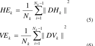
is ith block of CV2 subband and Nb=(NxM/64) is total number of blocks in each subbands at level 2 of wavlet decomposition. Step 2: Apply Discrete Cosine Transform (DCT) to each of the 8x8 block of both subbands. The energy-compaction characteristics of DCT in both sub-bands are used further to capture iris texture variations.Step 3: Calculate the energy of each 8x8 DCT block for both the subbands as,
2 1
1
||
||
1
Nki
k k
k
DH
N
HE
(5)
2 1
1
||
||
1
Nki
k k
k
DV
N
VE
(6)
Where, HEk is energy of kth DCT block of Horizontal detail wavlet subband, VEk is energy of kth DCT block of Vertical detail wavlet subband and Nk=64 is total number of DCT coefficients in each block vector.
Step 4: Form binary image template using both subband energy vectors representing iris texture variations using the following criteria.
For a kth block, if HEk is greater than VEk then set all pixels of corresponding 8x8 block of binary template as 255 i.e. all white pixels.
Else set all pixels of corresponding 8x8 block binary template as 0 i.e. all black pixels as shown in figure 6.
Fig.6. Binary image template formed using energies in DWT-DCT domain.
Step 5: Form final binary bit stream/unique code B corresponding to above binary iris image template using following rule,
If all pixels of 8x8 block is marked as 0 then corresponding bit will set as 0 else corresponding bit will set as 1.
b
(
1
),
b
(
2
),...,
b
(
N
b)
B
(7) [image:3.595.56.277.354.433.2] [image:3.595.54.284.560.664.2](K) obtained from user password and then the encrypted bit pattern template is stored.
3.4.1
Iris Template Matching Process
The matching algorithm consists of all the image processing steps that are carried out at the time of enrolling the encoded iris template in database. User also needs to input the same password to form user key (K). Once the bit encrypted bit pattern B’ corresponding to binary image formed is extracted, it is tried to match with all stored encrypted bit patterns B using simple boolean XOR operation. The dissimilarity measure between any two iris bit patterns is computed using Hamming Distance (HD) which is given as,
l N
l l
N
X
XOR
Y
HD
ll 1
(
)
1
(8)
Where, Nl=total number of bits in each bit pattern. As HD is a fractional measure of dissimilarity with 0 representing a perfect match, a low normalized HD implies strong similarity of iris codes.
4.
EXPERIMENTAL RESULTS
4.1
Experimental setup
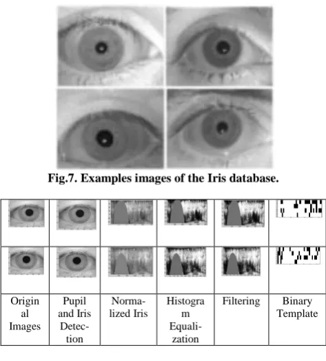
[image:4.595.48.285.462.724.2]In order to test the performance of the proposed method, a set of eye images obtained from the MMU and BATH databases [10] were used. Figure 7 shows an example of the eye images contained in this database. The data set consists of all grayscale images. Matlab R2009b is used on Intel Core 2 Duo (2.1 GHz) machine with 2GB RAM for the simulation purpose. The time needed for iris recognition was approximately 2-3 seconds. The searching period depends on the database size. There were total 80 numbers of irises stored in the database for this experiment. Figure 8 shows the outputs obtained at each processing stages along with the final binary image template.
Fig.7. Examples images of the Iris database.
Origin al Images
Pupil and Iris
Detec-tion
Norma-lized Iris
Histogra m
Equali-zation
[image:4.595.89.248.466.581.2]Filtering Binary Template
Fig.8. Results obtained at different stages.
A unique bit stream is constructed from it as shown in
K and final encrypted bit stream is stored in the database. The size of final bit stream is 128 bits only which is actually stored in the database. This drastically reduces size of total database along with providing higher security against compromise of template database.
Fig.9. Sample Unique Binary Bit Pattern created representing Iris Features
4.1.1
Performance Evaluation
Following metrics are used to evaluate the performance of the system.
1) False Acceptance Rate (FAR): FAR is the measure of the likelihood that the biometric security system will incorrectly accept an access attempt by an unauthorized user [11]. A system’s FAR typically is stated as the ratio of the number of false acceptances divided by the total number of identification attempts.
2) False Rejection Rate (FRR): A statistic used to measure biometric performance when operating in the verification task. The percentage of times the system produces a false reject. A false reject occurs when an individual is not matched to his/her own existing biometric template.
3) Equal Error Rate (EER): The rates at which both accept and reject errors are equal. In general, the lower the equal error rate value, the higher the accuracy of the biometric system. The EER is sometimes referred to as the "Crossover Error Rate".
The above performance parameters are evaluated by splitting total database of 100 persons into 80 and 20 persons. The database is created with 6 images per person i.e., total number of images in the database are 480. FRR is calculated by comparing seventh image of every individual with 480 images in the database of 80 persons. FAR is calculated by considering 20 individuals as imposters and are compared with 480 images in the database. Table 1 shows the resulted FRR and FAR for the proposed and existing technique.
Table1. FAR and FRR Comparison
User Proposed
FAR in % FRR in %
1-10 0.03 0.04
From the result, it can be observed that the proposed technique results in lesser FRR and FAR. The value of EER obtained is 0.122. From all the results obtained, it can be said that the proposed technique results in better accuracy in recognition/verification process.
5.
CONCLUSIONS
In this correspondence, we propose a novel robust iris recognition scheme having less computational complexity during verification phase due to smaller size of template database stored along with higher accuracy. Automatic segmentation is achieved through the use of the canny edge detector and hough transform for localising the iris and pupil regions. The energy-compaction characteristics of DCT are used to capture iris texture variations contained in both horizantal and vertical detail subbands of second level wavlet decomposition. In order to reduce the size of the database, binary bit stream instead of binary image is stored in the database for matching purpose. The reduced feature vector size provides faster recognition rate. Further to increase the security of the system, the bit stream obtained is first encrypted using the user key obtained from user password and then the encrypted bit pattern template is stored. Experimental results show that the proposed algorithm provides lesser FRR and FAR values during matching along with less computational complexity and better security. The future work will be carried out for real applications utilization such as generation of compact iris codes for mobile phones and PDAs.
6.
ACKNOWLEDGMENTS
Author would like to thank Defence Institute of Advanced Technology, DRDO Lab, Ministry of Defence, India for providing necessary facilities to carry out research. Author also would like to thank iris database repository providers for making available a large iris database for our research purpose.
7.
REFERENCES
[1] J. Daugman,“High confidence visual recognition of persons by a test of statistical independence,” IEEE Transactions on Pattern Analysis and Machine Intelligence, vol. 15, no. 11, pp. 1148–1161, 1993. [2] R. Wildes, “Iris recognition: An emerging biometric
technology,” Proceedings of the IEEE, vol. 85, no. 9, pp. 1348–1363, 1997.
[3] J. Daugman, “How iris recognition works,” IEEE Trans. Circuits Syst. Video Techn., vol. 14, no. 1, pp. 21–30, 2004.
[4] R. Sanchez-Reillo and C. Sanchez-Avila, “Iris recognition with low template size,” in AVBPA, ser. Lecture Notes in Computer Science, J. Big¨un and F. Smeraldi, Eds., vol. 2091. Springer, 2001, pp. 324–329. [5] Liu Yang, Yue Xue Dong, Liu Ying Fei and He Yan,
“Iris Recognition System Based on Choas Encryption,”
IEEE International Conference on Computer Design and Applications, vol 1, pp. 537-539, 2010.
[6] S. V. Sheela, P. A. Vijaya, “Iris Recognition Methods – Survey”, International Journal of Computer Applications, 2011.
[7] Zhonghua Lin and Bibo Lu, “Iris Recognition Method Based on the Imaginary Coefficients of Morlet wavelet Transform,” Seventh IEEE international Conference on Fuzzy Systems and Knowledge Discovery, pp. 573-577, September 2010.
[8] Jing Huang, Xinge You, Yuan Yan Tang, “Iris Recognition Based on Non Separable Wavelet,” IEEE International Conference on Systems, Man and Cybernetics, pp. 1552-1557, 2008
[9] Mohammed A M Abdullah, F H A Al-Dulaimi, Waleed Al-Nuaimy and Ali Al-Ataby, “Smart Card with Iris Recognition for High Security Access Environment,” IEEE International Conference on Biomedical Engineering, pp. 382-385, 2011.
[10] D. Monro, “Bath University iris database,” University of Bath, Bath, School of Electronic and Electrical Engineering, 2008,http://www.bath.ac.uk/elec-eng/research/sipgl.
[11] Li Ma, Tieniu Tan, Yunhong Wang, Dexin Zhang, “Personal Identification based on Iris Texture Analysis”, IEEE Transactions on Pattern Analysis and Machine Intelligence, Vol.25, No.12, pp. 1519 – 1533, 2003. [12] Beauchamp, K.G., 1984, “Applications of Walsh and
Related Functions: with an Introduction to Sequency Theory”, Academic Press, London, 295-300.
[13] Zhihua, L. and Qishan, Z.,1983, “Ordering of Walsh functions”, IEEE Transactions on Electromagnetic Compatibility, 2, 115–119.
[14] Brown, R.D., 1977, “A recursive algorithm for sequency-ordered fast Walsh transforms”, IEEE Transactions on Computers, C-26, 8, 819–822.
[15] C.Anand Deva Durai, M.Karnan, “Iris Recognition Using Modified Hierarchical Phase-Based Matching (HPM) Technique”, IJCSI International Journal of Computer Science Issues, Vol. 7, Issue 3, No 8, May 2010
[16] L. Ma, T. Tan, Y. Wang, and D. Zhang, “Personal Identification Based on Iris Texture Analysis,” IEEE Trans. Pattern Analysis and Machine Intelligence, vol. 25, pp. 1519-1533, 2003.