Design Approach of High Speed Parallel
Processed Viterbi Decoder with Pipelining
Technique
Ms Mohini lade
1, Dr. N.N.Mhala
2, Prof.S.M.Sakhare
3M.Tech Scholar, Dept. of Electronics Engineering, SDCOE, Selukate, Wardha,India1 Professor and Head,Dept. of Electronics Engineering, BDCOE, Sewagram, Wardha, India2
Assistant Professor, Dept. of Electronics Engineering, SDCOE ,Selukate, Wardha,India3
ABSTRACT: Attenuation, distortion, interference and noise affect data transmission over wireless channels that influence the receiver‘s ability to receive correct information. Convolution codes are used in many communication systems because of their excellent error-control performance. A convolutional coding is done by combining the fixed number of inputs bits. The input bits are stored in the fixed length shift register and they are combined with the help of mod-2 adders. This operation is similar to binary convolution and hence it is known as convolution coding. Convolutional encoding with Viterbi decoding is a powerful method for forward error correction. The High-speed Viterbi decoders for convolutional codes are of great interest for high-data-rate applications. This proposal presents the convolution encoder and viterbi decoder for constraint length 9 and code rate 1/3. This design presents an efficient coding technique for wireless communication, using VHDL. It is simulated and synthesized using Xilinx 13.2. The data stream is processed parallel with pipelined technique in the viterbi decoder. The parallel processed viterbi decoder with pipelining uses 3-bit soft decision decoding for the estimation of original data stream. In this dissertation the given input sequence that to be transmitted has been encoded by using convolutional encoder and received sequence is decoded by the high speed parallel Processed Viterbi decoder with pipelined technique and the estimated original sequence is produced. With the proposed design the power consumption is reduced nearly by 8% moreover speed of processing is increased.
KEYWORDS: Convolution encoder, viterbi decoder, Constraint length, code rate, parallel process, pipelined technique.
I. INTRODUCTION
A. Convolutional Encoder:
Convolutional code is a type of error-correcting code in which each (n≥k) k-bit information symbol (each k bit string) to be encoded is transformed in to an n-bit symbol, where k/n is the code rate (n≥k) and the transformation is a function of the last k information symbols, where K is the constraint length of the code. A Convolution Encoder accepts an input stream of message and generates encoded output streams to be transmitted. In this process for one input bit the encoder generates more than one output bits and these redundant symbols in output bit pattern makes the transmitted data more immune to the noise in the channel.[12] The redundant bits help to decide and correct the errors in received pattern. For the standardization a terminology was generated as summarized:
M = Length of the shift registers stage in the encoder. This indicates the number of shift registers present in the convolutional encoder.
Constraint Length (K) = The constraint Length equal to Number of Shift register plus one. This number represents the number of input bits required to generate a unique output pattern in the encoder. A constraint length of K=3 means that each output symbol depends on the current input symbol and the two previous input symbols stored in the shift register.
Number of States = Defines the maximum number of states that is possible to be mapped by the combinations of the m number of input bits for the convolution encoder.
S=2(m-1)
m=This indicates the total length of input message
1) R=Convolution Code Rate , It is defined as The Number of input bits to create a symbol at the input (k)/ Number of output bits in a symbol at the output (n).
R=k/n Where,
k= number of input to the convolutional encoder n=number of outputs of convolutional encoder
For example, 1/3 code rate means each bit entering the encoder results in 3 bits leaving the encoder. The encoder has n modulo-2 adders, and n generator polynomials one for each adder. This process doubles the number of input bits at the output. For example, a 4-bit input is converted into an 8-bit output, 8-bit input into a 16-bit output and so on. The block diagram of convolution encoder is shown in Fig 1. To generate the output, the encoder uses three values of the input signal, one present and two past. The set of past values of input data is called a state. The number of input data values used to generate the code is called the constraint length. A convolutional coding is done by combining the fixed number of inputs bits. The input bits are stored in the fixed length shift register and they are combined with the help of mod-2 adders. This operation is equivalent to binary convolution and hence it is called convolution coding[16][4][7].
Fig.1. Functional Block Diagram of Convolution Encoder
Each set of outputs is generated by EX-OR ing a pattern of current and shifted values of input data. The pattern used to generate the coded output value can be expressed as binary strings called ―Generator Polynomials‖ (GP)[13]. The MSB of the GP corresponds to the input; the LSBs of the GP correspond to the state [13]. The encoder that has been designed is a linear, non – systematic, convolution encoder [3].Tthe convolutional encoder and Viterbi decoder, which is used in the digital communication system. Here, X is the input data steam, which is given into the convolutional encoder and it produces the encoded data stream (Y). The encoded data stream (Y) is given to the channel in the presence of noise. Hence, it produces the noise added encoded data stream (R). Finally, data stream (R) is given to the Viterbi decoder that produces the estimated data stream (Z) applied at the input.
B. Viterbi Decoder :
viterbi decoder consist of branch matric unit, Path matric Unit, Add compare select Unit, Survival Memory Unit.
Branch Matric Unit:
The comparison between received code symbol and expected code symbol is done by branch metric unit. It also counts the number of differing bits. It is the smallest unit in the Viterbi decoder. The measured value of the BMU can be the Hamming distance in case of the hard input decoding or the Euclidean distance in case of the soft input decoding .[1][3][4]The BMU performs simple add and subtract operations on the decision bits to generate the output , and the output of the BMU is still in a two‘s complement format. The bit serial format of the BMs is generated by the parallel to serial module at the output of the BMU.[16][2]
Path Matric Unit:
The partial path metric of each branch is computed by the use of two adders. The partial path metric is compared by the comparator and an appropriate branch is selected by the selector. The selector selects the smaller value and stored that value as the new path metric for each state. [8] The corresponding bit decision is transferred to the SMU.[1]
Survivor Memory Unit :
The Survivor Memory Unit receives the bit decision from the PMU. This will produces the decoded sequence. After finishing the SMU, it is important to perform the trace back module. When the trellis diagram is finished, the trace-back module will search the maximum likelihood path from the final state which is state0 to the beginning state which is state0. Each time, the trace-back block just left shifts one bit of the binary state number and add one bit from the survivor path metric to compute the previous state. It stores the path information in the form of an array of recursive pointers. By doing this, the most likelihood path is found.[4]
C. Viterbi Decoder Algorithm:
The Viterbi algorithm has been known as a maximum likelihood decoding algorithm for convolutional codes.[1] Let us consider a simple example for illustrating the principle of Viterbi algorithm. Assume that a car that has 3 states forward, stop and reverse with the condition that a transition from forward to reverse is not allowed. In other words, it implies that the car first enter the stop state and then enter the reverse state. Hence, when we receive the information through the processes of forward, reverse and stop, we can safely interpret it as – forward, stop and reverse as this is a ―maximum likelihood sequence‖. The Viterbi algorithm uses the trellis diagram to compute the path metric value (accumulated distance) from the received sequence to the possible transmitted sequences. The total number of such trellis paths increases exponentially with the number of stages in the trellis. The maxiumhood likelihood viterbi decoder is classified into two type.
Hard decision Decoding: If the received signal is converted into two levels, either zero or one, it is called hard decision
soft decision Decoding: If the input signal is quantized and processed for more than two levels, it is called soft decision.[13]
The algorithm can be broken down into the following three steps.
1. Weigh the trellis; that is, calculate the branch metrics.
2. Recursively computes the shortest paths to time n, in terms of the shortest paths to time n-1. In this step, decisions are used to recursively update the survivor path of the signal. This is known as add-compare select (ACS) recursion.[7]
Fig.2. Viterbi decoder algorithm
II. RELATED WORK
Previous paper describe the analysis and implementations of a pipelined & reduced-complexity decode approach, the adaptive Viterbi algorithm (AVA). AVA design is implemented in reconfigurable hardware to take full advantage of algorithm parallelism and specialization. Run-time dynamic reconfiguration is used in response to changing channel noise conditions to achieve improved decoder performance. Look ahead technique is studied for extracting vectorized output bits without taking into consideration the hardware cost involved. It improves the throughput rate. Implementation parameters for the decoder have been determined through simulation and the decoder has been implemented on a Xilinx FPGA SPARTAN 3E Kit. This approach has shown significant speedup versus both software implementations on previous FPGA-based implementations. Through experimentation it was shown that dynamic reconfiguration can be used effectively to improve overall performance by at least 20%. Reconfiguration was performed on the basis of channel noise to achieve a consistent bit-error rate. If channel noise increases, a more accurate but slower running decoder is swapped into the FPGA hardware. Reduced channel noise leads to the opposite effect. With a throughput of 20 Mbps, the proposed decoder is suitable for use in receiver architecture of 3G cellular code division multiple access environments.[5]
Wireless devices such as hand phones and broadband modems rely heavily on forward error correction techniques for their proper functioning, thus sending and receiving information with minimal or no error, while utilizing the available bandwidth. Major requirements for modern digital wireless communication systems include high throughput, low power consumption and physical size. This paper presents the design of an efficient coding technique for wireless communication, using FPGA, a four state convolutional encoder and decoder were designed respectively, an efficient decoder with high speed and low power consumption was designed using the memory less decoder design, the maximum frequency of the device clock was recorded as 185 MHz, with a coding gain of 4dB over uncoded BPSK for BER of 10-10 found through MATLAB simulation. The encoder and decoder were implemented on altera DE1 board, with cyclone II FPGA having a maximum frequency of 50MHz.[6]
Silicon Area, Decoding Time and Power Consumption. We have developed Viterbi Decoder on Spartan 3A FPGA by utilizing both method and Synthesis result shows that Trace back method is more efficient in term of Chip Area Utilization so as will be Power Consumption in comparision with Register Exchanged Method. Also this paper tested the functionality ofthe Viterbi Decoder Code implemented on FPGA by designing a Test Bench for performing Error Detection and Correction[4]
In a previous paper, A Viterbi decoder uses the Viterbi algorithm for decoding a bit stream that has been encoded using Forward error correction based on a Convolutional code. The maximum likelihood detection of a digital stream is possible by Viterbi algorithm. Author present a design and implementation of Convolutional encoder and Viterbi decoder with a constraint length of 7 and code rate of 1/2. This is realized using Verilog HDL. It is simulated and synthesized using Modelsim PE 10.0e and Xilinx 12.4i. [1]
The problem of survival memory management of a Viterbi decoder (VD) was solved by introducing a novel pointer implementation for the register exchange method, where a pointer is assigned to each row of memory in the survivor memory unit (SMU). The content of the pointer which points to one row of memory is altered to point to another row of memory, instead of copying the contents of the first row to the second. In this paper, the one-pointer VD is proposed; if the initial state of the convolutional encoder is known, the entire SMU is reduced to only one row. Because the decoded data bits are generated in the required order, even this row of memory is dispensable. The PVD proposed was further improved to reduce its power consumption. The MLVD is a memoryless implementation of the VA, and successfully decodes the continuous data encoded by aWCDMA convolutional encoder. The power reduction is as high as 50% and the latency is only 2 data bits. The new implementation is realized by applying the pointer concept to the RE implementation, and by using trellis truncation for every bits encoded. The BER for the MLVD is estimated to be for a SNR of 4.2 dB with a coding gain of 2.6 dB. The MLVD along with an on-chip convolutional encoder was implemented on a Xilinx 2V6000 chip to demonstrate both the design‘s functionality and feasible implementation. The hardware and computational overhead of this implementation is only a 256-to-1 decoder, which is switching at the data rate frequency. Increasing the MLVDs performance by increasing the constraint length or by varying the survivor path length is still to be investigated. Thus, the one-pointer architecture, referred to as memoryless VD (MLVD), reduces the power consumption of a traditional traceback VD by approximately 50%, but has some performance degradation. A prototype of the MLVD with a one third convolutional code rate and a constraint length of nine is mapped into a Xilinx 2V6000 chip, operating at 25 MHz with a decoding throughput of more than 3 Mbps and a latency of two data bits.[2]
III. PROPOSED METHOD
A. Development of Convolution Encoder:
Convolution code are commonly specified by three parameters k , n , m or K where k is the number of input , n is the number of output , m=K-1 which represent number of shift register and K represent length of convolutional Encoder. The efficiency of convolution code is measured in terms of code rate, which is calculated as k/n.
Fig.3. Convolutional Encoder of K= 9 & k/n =1/3
In this diagram at the first clock cycle input bit is enter to flip-flop register 1 ie at FF1 and then it is shifted to next shift register say FF2 and so on. The output is the X-OR combination of input and shift register bit depend on Generator Polynomials . The developed convolutional Encoder‘s outputs are depends on following equations.
i1 = b0+b1; (1)
i2 = b0+ b1+b2; (2)
i3 = b0+ b1+ b2; (3)
If Input Bit is X = {01101}
Then Encoded Bit Y={101101101011011011011101101101011101101101101101}
Shift register S={101100000}
In this dissertation, the convolutional Encoder is of constraint length(K) 9 and code rate (R) 1/3. The Encoder output i.e. the code word is the combination of i1, i2 ,i3.
B Development of Viterbi Decoder:
The development of viterbi decoder is done with the development of branch matric unit and development of Add Compare Select Unit. The branch Matric unit and Add Compare Select Unit Added together to form Viterbi Decoder.
Fig .4. Block Diagram of Viterbi Decoder
Figure 4shows the block diagram viterbi decoder. It consist of branch matric unit, Path matric Unit, Add compare select Unit, Survival Memory Unit.
Branch Matric Unit: For binary convolutional codes, it is proven that linear distances (Hamming distances) can be used as the optimum branch metrics (BMs). For three 3-bit soft decision input bits, each ranging from-3 to 3, eight 8-bit BMs are generated. The BMU performs simple add and subtract operations on the decision bits to generate the output , and the output of the BMU is still in a two‘s complement format. The bit serial format of the BMs is generated by the parallel to serial module at the output of the BMU, then the bit serial format BM(0-7) is fed into the add-compare-select unit ( ACSU).
Add Compare Select Unit: The ACS unit is the second functional unit of the Viterbi decoder. The ACS unit calculates the path matric (Pm) which is used to determine Survivor path.
Pm (next stage) = Pm (previous stage) + Bm(next stage)
The two adders compute the partial path metric of each branch, the comparator compares the two partial metrics, and the selector selects an appropriate branch. The new partial path metric updates the state metric of state.
Fig.6. Block Diagram of Add Compare select Unit
Parallel Processing with Pipelining Technique:
Pipelining is one of the popular methods to realize high performance computing platform. Usually, if a processor is pipelined with N stages of registers, then the delay between the pipeline stages is reduced by almost a factor of N[] Thus, it is possible to maintain the operating frequency, while the supply voltage is aggressively scaled down. [9]. Pipelining is a technique where multiple instruction executions are overlapped. It comes from the idea of a water pipe: continue sending water without waiting the water in the pipe to be out. By pipelining the unit of a system we can produce result in every clock cycle
It leads to a reduction in the critical path. It can either increase the clock speed (or sampling speed) or reduces the power consumption at same speed in a DSP system. Pipelining is a concept to reduce the delay in the critical path. It is done by adding registers or latches in the data path .By eliminating the delay in the critical path the speed and throughput is increased [9]. Pipelining is a popular technique to increase throughput of a high speed system, which divides total system into several small cascade stages and adds some register to synchronize outputs of each stages. a
pipeline is a set of data processing elements connected in series, where the output of one element is the input of the next one. The elements of a pipeline are often executed in parallel or in time-sliced fashion; in that case, some amount of buffer storage is often inserted between elements.
The Pipeline pattern uses parallel tasks and concurrent queues to process a sequence of input values. Each task implements a stage of the pipeline, and the queues act as buffers that allow the stages of the pipeline to execute concurrently, even though the values are processed in order. You can think of software pipelines as analogous to assembly lines in a factory, where each item in the assembly line is constructed in stages. The partially assembled item is passed from one assembly stage to another.
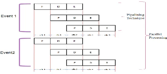
Fig.7. Parallel Processing with Pipelining Technique
Figure 7 clear the pipelining and parallel processing concept in the processor. Suppose in the program if it consist of three instruction and this instructions are process pipelined then at a clock cycle one first instruction is fetch, at the second clock cycle that first instruction is decoded but simultaneously second instruction is fetch . In the third clock cycle the first instruction is executed and at the same clock cycle only second instruction is decoded and third instruction fetch. So for complete execution of three instructions by using pipelining process required 5 clock cycle but in normal clock cycle it required 9 clock cycle. That is why we can say that pipelining required less execution timing as compared to normal processing. In the parallel processing the two instructions are executed at a same clock cycle. so to execute two event which consist of three instruction each required only 5 clock cycle instead of 18 clock cycle.
IV. SIMULATION RESULTS
The This design has been implemented on Xilinx 13.2 and synthesized for VHDL. Simulation based verification is one of the method for functional verification of a design. In this method, test inputs are provided using standard test benches. The test bench forms the top modules that instantiates other modules. Simulation based verification ensure that the design is functionally correct when tested with given set off inputs.
A. Xilinx Results for Normal Viterbi Decoder :
Execution Time :-
Figure 8 shows the execution time of normal convolutional encoder and viterbi decoder system. The execution time of normal convolutional encoder and viterbi decoder system is 0.885nsec.
Area :-
Figure 9 shows the area of Normal Convolutional encoder and Viterbi Decoder system.
Fig.9. Area of normal convolutional encoder and viterbi decoder system.
Power Consumption :-
Figure 10. shows power consumption of normal convolutional encoder and viterbi decoder system. The power consumption of normal convolutional encoder and viterbi decoder is 0.00037 watt.
Fig.10. Power consumption of normal convolutional encoder and
viterbi decoder system
Delay :-
Figure11. shows delay of normal convolutional encoder and viterbi decoder system. The delay of normal convolutional encoder and viterbi decoder is 8.759 nsec.
Fig.11. Delay of normal convolutional encoder and viterbi decoder system.
B. Xilinx Results for Parallel Processed Viterbi Decoder with pipelining technique:
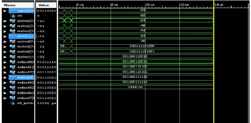
Waveform and RTL view :
Fig.12. Waveform of Parallel Processed Viterbi Decoder with pipelining technique system .
Execution Time :-
Figure 13 shows the execution time of convolutional encoder and parallel processed viterbi decoder with pipelining pipelining. The execution time of convolutional encoder and parallel processed viterbi decoder with pipelining technique is 0.83nsec.
Fig.13. Execution time of convolutional encoder and parallel processed viterbi decoder with pipelining technique system. Area :
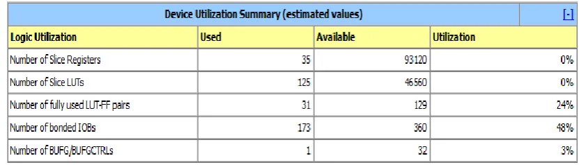
Figure 14. shows the area of convolutional encoder and parallel processed viterbi decoder with pipelining technique.
Fig.14. Area of convolutional encoder and Parallel Processed Viterbi
Power Consumption:-
Figure 15. shows the power consumption of convolutional encoder and high speed parallel processed viterbi decoder with pipelining technique. The power consumption of convolutional encoder and parallel processed viterbi decoder with pipelining technique system is 0.00034 Watt.
Fig.15. Power consumption of convolutional encoder and
Parallel processed viterbi decoder with pipelining technique.
Delay :-
Figure 16 shows the Delay of convolutional encoder and parallel processed viterbi decoder with pipelining technique system. The Delay of convolutional encoder and parallel processed viterbi decoder with pipelining technique is 0.342.
Fig.16. Delay of convolutional encoder and parallel processed viterbi decoder with pipelining technique system.
Comparison Between Normal Convolutional Encoder And Viterbi Decoder System And Convolutional Encoder And Parallel Processed Viterbi Decoder With Pipelining Technique System :-
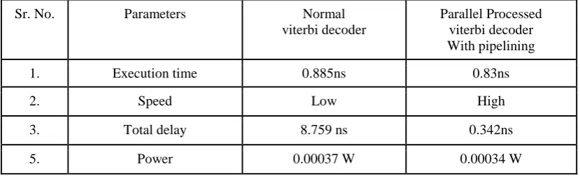
Table 1. shows the comparison between normal convolutional encoder and viterbi decoder system and convolutional encoder and parallel processed viterbi decoder with pipelining technique system in terms of execution time, speed, delay and power consumption.
Table 1. comparison between normal convolutional encoder and viterbi decoder system and convolutional encoder and parallel processed viterbi decoder with pipelining technique system
Sr. No. Parameters Normal
viterbi decoder
Parallel Processed viterbi decoder With pipelining
1. Execution time 0.885ns 0.83ns
2. Speed Low High
3. Total delay 8.759 ns 0.342ns
V. CONCLUSION AND FUTURE WORK
In this paper the design of high speed parallel processed viterbi decoder with pipelining technique is done. The design has been simulated in Xilinx13.2 for the constraint length of K=9 and code rate of 1/3 input sequence. The given input sequence has been encoded by using convolutional encoder and transmitted sequence is decoded by the Viterbi decoder and the estimated original sequence is produced. The design uses pipelining and parallel processing concept in the viterbi decoder. Speed is increased as compared with normal viterbi decoder System. The power consumed by high speed parallel processed viterbi decoder with pipelining technique system is less as that of normal viterbi decoder system. The power consumption of high speed parallel Processed viterbi Decoder with Pipelined technique is decrease by 8.82%as compared to normal viterbi decoder.The designed high speed parallel processed viterbi decoder with pipelining technique system has less delay in its processing then the Normal viterbi decoder system. In the future, we will taken up for decreasing the area and power consumption.
REFERENCES
1. V.Kavinilavu1, S. Salivahanan, V. S. Kanchana Bhaaskaran2, Samiappa Sakthikumaran, B. Brindha and C. Vinoth, ―Implementation of convolutional encoder and viterbi decoder using verilog HDL‖, IEEE trans. ICECT, vol. 1, pp. 297-300, April 2011.
2. Dalia A. El-Dib, M. I. Elmasry ―Memoryless Viterbi Decoder‖ IEEE Transactions On Circuits And Systems—Ii: Express Briefs, Vol. 52, No. 12, December 2005.
3. Hiral Pujara1, Pankaj Prajapati2 ―RTL Implementation of Viterbi Decoder using VHDL‖ IOSR Journal of VLSI and Signal Processing (IOSR-JVSP) Volume 2, Issue 1 (Mar. – Apr. 2013), PP 65-71 e-ISSN: 2319 – 4200, p-ISSN No. : 2319 – 4197.
4. Anubhuti Khare, Manish Saxena, Jagdish Patel, ―FPGA Based Efficient Implementation of Viterbi Decoder‖ International Journal of Engineering and Advanced Technology (IJEAT) ISSN: 2249 – 8958, Volume-1, Issue-1, October 2011.
5. Nitin S. Sonar, Dr. Faris S. Al-Naimy, Dr. R.R. Mudholkar, ―An Improved Dynamically Reconfigurable Pipelined Adaptive Viterbi Decoder for High Throughput‖ International Journal of Engineering and Innovative Technology (IJEIT) Volume 2, Issue 7, January 2013 ISSN: 2277-3754 ISO 9001:2008.
6. Shaina Suresh, Ch. Kranthi Rekha, Faisal Sani Bala ,‖ Performance Analysis of Convolutional Encoder and Viterbi Decoder Using FPGA‖ International Journal of Engineering and Innovative Technology (IJEIT) Volume 2, Issue 6, December 2012, ISSN: 2277-3754 ISO 9001:2008
7. Wong, Y., Jian, W., HuiChong, O., Kyun, C., Noordi, N. ―Implementation of Convolutional Encoder and Viterbi Decoder using VHDL‖, Proceedings of IEEE International conference on Research and Development Malaysia, November 2009.
8. Yin Sweet Wong, Wen Jian Ong, Jin Hui Chong, Chee Kyun Ng and Nor Kamariah Noordin, ―Implementation of convolutional encoder and viterbi decoding using VHDL‖, Proceedings of SCOReD, pp. 22-25, Nov. 2009.
9. Keshab K. Parhi, MARCH (2004), "An Improved Pipelined MSB-First Add Compare Select Unit Structure for Viterbi Decoders", IEEE Transactions On Circuits And Systems—I: Regular Papers, Vol. 51, And No. 3
10. Chaiwat Keawsai1, Keattisak Sripimanwat 2, and Attasit Lasakul3 ―Modified Registe Exchange Method of Viterbi Decoder for 3GPP Mobile System‖
11. Muhammad Shoaib Bin Altaf ―A Parallel Viterbi Decoder Implementation for High Throughput‖
12. Mahe Jabeen, Salma Khan ―Design of Convolution Encoder and Reconfigurable Viterbi Decoder‖ International Journal of Engineering and Science ISSN: 2278-4721, Vol. 1, Issue 3 (Sept 2012), PP 15-21.
13. L. Lang; C.Y. Tsui and R.S. Cheng, ―Low power soft output Viterbi decoder scheme for turbo code decoding,‖ Conference-Paper, ISCAS ‗97(Cat. No97CH35987). IEEE, New York, NY, USA, 4 vol. Lxvi+2832 pp. p. 1369-1372 vol.2, 19
14. A.J.Viterbi, ―Error bounds for convolutional coding and an asymptotically optimum decoding algorithm‖, IEEE Tran. on Inform.Theory, Vol. 2, Pp. 260-269, Apr. 1967.
15. Hema.S, Suresh Babu.V and Ramesh.P, ―FPGA Implementation of Viterbi decoder‖ proceedings of the 6th WSEAS ICEHWOC, Feb.2007