Experimental Investigation and Mechanical
Characterization Analysis of Sa387 Gr12 By
Using TIG Welding Process
V.Kannan1, Kolanjirajan.M2, Saranraj.D3, Sasikumar.P4, Selvendran.K5
Assistant Professor, Department of Mechanical Engineering, TRP Engineering College, Tiruchirapalli, India1
UG Scholars, Department of Mechanical Engineering, TRP Engineering College, Tiruchirapalli, India 2,3,4,5
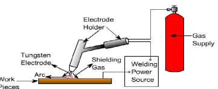
ABSTRACT: Tungsten inert gas (TIG) welding is the most popular gas shielding arc welding process used in many industrial fields. Other arc welding processes have limited quality when they are compared to TIG welding processes. However, TIG welding also needs improvements regarding spatter reduction and weld quality of the bead. Shielding gas in TIG welding is desirable for protection of atmospheric contamination. TIG welding process has the possibility of becoming a new welding process giving high quality and provides relatively pollution free.A387 Grade 12 chrome moly steel is a boiler plate steel according to the ASTM/ASME standard A387/A387M.A387 Grade 12 is designed for use in pressure vessels and heat exchangers where there is an elevated temperature.it is described as an alloyed high temperature pressure vessel steel. The addition of chrome and molybdenum in the steel making makes this plate suitable for use at high temperatures whilst also giving them some corrosion resistant properties. whilst not as corrosion resistant stainless steels, chrome moly plates in the A387 family are often a cost effective substitute in lower risk areas.
I. INTRODUCTION
Fig 1.1: Schematic Diagram of TIG Welding System. Process parameters of TIG welding
Welding Current Welding Voltage Inert Gases Welding speed:
II. LITERATURE REVIEW
J. Dutta,et al[1] investigated reveals an elaborate analysis of variation of thermal properties of high carbon steel plate butt joints formed by DC Gas Tungsten Arc (GTA) welding. Vishnu V.S,et al[2] analyzed 3D thermo-mechanical simulation model was developed to predict distribution of temperature and residual stresses during Tungsten Inert Gas (TIG) double-side arc welding (DSAW) process on a low carbon steel plate. The simulated results show that the residual stresses are tensile at the weld poolregion and as the distance from the weld line increase it tends to compressive. Also found that welding process parameters in welded structures are the most influential parameter for the occurrence and control of residual stresses. M.PalPandi,et al[3] carried out thermo-mechanical finite element analysis has been performed to assess the residual stress in the butt weld joints of aluminum Alloy AA7075 plates by utilizing the commercial software package ABAQUS. The study shows the effects of varying heat input, welding speed
on the thermo-mechanical responses of the weldment after cooling down to room temperature. M SUNDAR,et al[4]
analyzed welding is a reliable and effective metal fabrication process which is widely used in industries and study on a single pass butt-welding specimen by using Finite Element Method to illustrate the temperature distribution, distortion and residual stress field developed in the weldment. They developed relationships between the parameters and response
based on the simulation result, which are found to be in good agreement. A.RASOOL MOHAIDEEN,et al[14] studied the
heterogeneous nature of weldments demands an additional processing to retain and/or improve the joint properties. They studied the influence of postweld heat treatment on the fracture toughness on alloy steel weldments. Fracture toughness soft heattreated weldments was determined using standard CTOD test and the results were correlated.
III. PROBLEM IDENTIFICATION
In many cases the welder needs only to know the techniques of actual welding and does not need to be concerned about the type or grade of steel being welded. This is because a large amount of steel used in fabricating a metal structure is low Carbon or plain carbon steel (also called mild steel). When welding these steels with any of the common arc welding processes like Stick Mig or Tig there are generally few precautions necessary to prevent changing the properties of the steel.
be involved in following a specific welding procedure to ensure weld metal and base metal has the desired strength characteristics.
IV. EXPERIMRNTAL DESIGN DESIGN OF EXPERIMENT
Table 4.1 Process parameters and their levels Levels Process parameters
PEAK CURRENT BASE CURRENT GAS PR
1 25 130 4
2 30 150 5
3 35 170 6
4.2 DESIGN OF ORTHOGONAL ARRAY
Table: 4.2 AN ORTHOGONAL ARRAY L9 FORMATION
TRIAL NO. DESIGNATION BASE PEAK Gas pr
1 A1B1C1 25 130 4
2 A1B2C2 25 150 5
3 A1B3C3 25 170 6
4 A2B1C2 30 130 5
5 A2B2C3 30 150 6
6 A2B3C1 30 170 4
7 A3B1C3 35 130 6
8 A3B2C1 35 150 5
9 A3B3C2 35 170 4
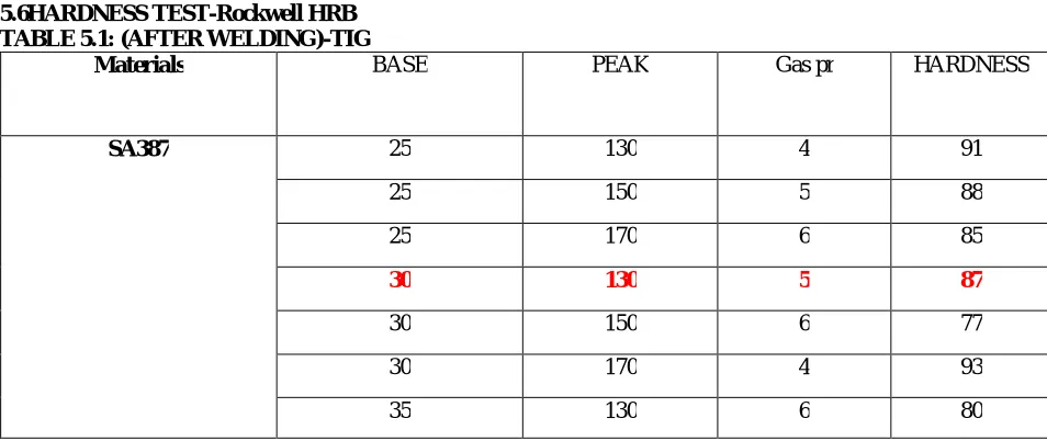
V. EXPERIMENTAL ANALYSIS 5.6HARDNESS TEST-Rockwell HRB
TABLE 5.1: (AFTER WELDING)-TIG
Materials BASE PEAK Gas pr HARDNESS
SA387 25 130 4 91
25 150 5 88
25 170 6 85
30 130 5 87
30 150 6 77
30 170 4 93
35 150 5 77
35 170 4 77
DEPTH OF PENETRATION
Fig 6.1 view of test plate
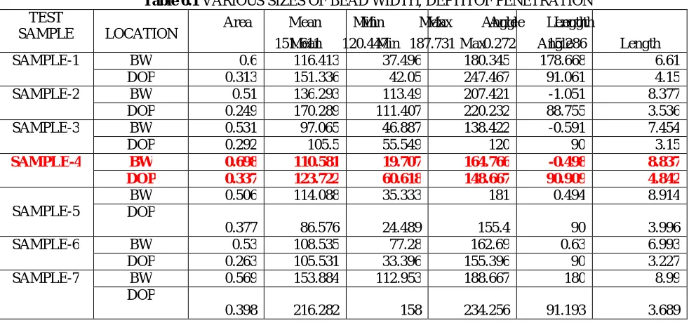
VI. VARIOUS SIZES OF BEAD WIDTH, DEPTH OF PENETRATION AND HEAT AFFECTED ZONE-SA387Gr12-GTAW
Table 6.1 VARIOUS SIZES OF BEAD WIDTH, DEPTH OF PENETRATION TEST
SAMPLE LOCATION Area Mean Min Min Max Max Angle Angle Length Length
151.611 Mean 120.447 Min 187.731 Max 0.272 Angle 15.286 Length
SAMPLE-1 BW 0.6 116.413 37.496 180.345 178.668 6.61
DOP 0.313 151.336 42.05 247.467 91.061 4.15
SAMPLE-2 BW 0.51 136.293 113.49 207.421 -1.051 8.377
DOP 0.249 170.289 111.407 220.232 88.755 3.536
SAMPLE-3 BW 0.531 97.065 46.887 138.422 -0.591 7.454
DOP 0.292 105.5 55.549 120 90 3.15
SAMPLE-4 BW 0.698 110.581 19.707 164.766 -0.498 8.837
DOP 0.337 123.722 60.618 148.667 90.909 4.842
SAMPLE-5
BW 0.506 114.088 35.333 181 0.494 8.914
DOP
0.377 86.576 24.489 155.4 90 3.996
SAMPLE-6 BW 0.53 108.535 77.28 162.69 0.63 6.993
DOP 0.263 105.531 33.396 155.396 90 3.227
SAMPLE-7 BW 0.569 153.884 112.953 188.667 180 8.99
DOP
SAMPLE-8 BW 0.499 99.125 43.826 123.873 -178.379 8.148 DOP
0.364 104.479 50.333 132.333 90 3.381
SAMPLE-9 BW 0.671 184.613 119.244 211.759 179.597 10.912
DOP
0.304 214.453 176 233.667 90 3.919
6.2 TENSILE TEST
Table 6.2 TENSILE TEST REPORT
SAMPLES WIDTH
XTHICK
AREAmm2 T.LOAD
N
TENSILE STRENGTH
Mpa
T3-LEVEL1 31.20X5.00 156.00 322.00 206
T6-LEVEL2 31.50X5.50 157.50 568.00 361
T9-LEVEL-3 31.12X5.00 155.80 437 238
Level 2 is more Tensile stress compared than other level
VII. ULTRASONIC RESULT
MACHINESPECIFICATION UT INSTRUMENT: PX20
Transducer angle : 70o 4 MHZ, Technique : pulse Echo, Material ; D3 Thickness : 5MM
Table7.1 Ultrasonic report
S.NO
BASE CURRENT
PEAK CURRENT
GAS
PRESSURE INDICATIONS
1. 25 130 4 ICP &Por
2. 25 150 5 ICP
3. 25 170 6 NI
4. 30 130 5 NI
5. 30 150 6 Cr
6. 30 170 4 Cr
7 35 130 6 UC
8 35 150 5 EP
9
35 170 6
VIII. RESULT AND DISCUSSION Table 8.1 process parameter optimization TRIAL
NO. DESIGNATION
VOLT AMPS GAS PRESSURE
HARDNESS SNRATIO VALUE
1 A1B1C1 25 130 4 91 -39.1808
2 A1B2C2 25 150 5 88 -38.8897
3 A1B3C3 25 170 6 85 -38.5884
4 A2B1C2 30 130 5 87 -38.7904
5 A2B2C3 30 150 6 77 -37.7298
6 A2B3C1 30 170 4 93 -39.3697
7 A3B1C3 35 130 6 80 -38.0618
8 A3B2C1 35 150 5 77 -37.7298
9 A3B3C2 35 170 6 77 -37.7298
Taguchi Analysis: HARD versus VOLT, AMPS, GASPRESSURE
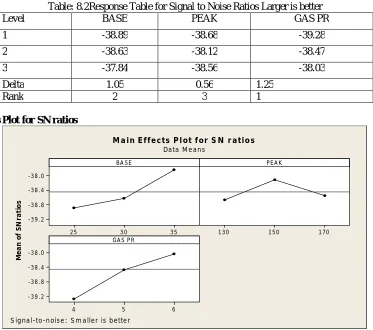
Table: 8.2Response Table for Signal to Noise Ratios Larger is better
Level BASE PEAK GAS PR
1 -38.89 -38.68 -39.28
2 -38.63 -38.12 -38.47
3 -37.84 -38.56 -38.03
Delta 1.05 0.56 1.25
Rank 2 3 1
Main Effects Plot for SN ratios
3 5 3 0
25 -3 8 . 0
-3 8 . 4
-3 8 . 8
-3 9 . 2
1 70 1 5 0
1 3 0
6 5
4 -3 8 . 0
-3 8 . 4
-3 8 . 8
-3 9 . 2
BA S E
M e a n o f S N r a ti o s
P E A K
GA S P R
M a in E f f e c ts P l ot f or S N r atio s
Da ta M e a n s
S ig na l-to-n ois e : S m a lle r is b e tte r
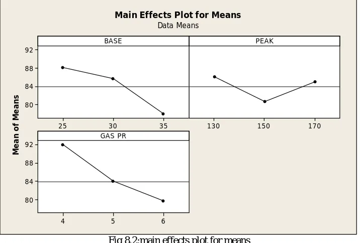
Main Effects Plot for Means
35 30
25 92
88
84
80
170 150
130
6 5
4 92
88
84
80
BASE
M
e
a
n
o
f
M
e
a
n
s
PEAK
GAS PR
Main Effects Plot for Means Data Means
Fig 8.2:main effects plot for means
Table: 8.3 analysis of variance for hard, using adjusted ss for tests
SOURCE DF SeqSS Adj SS
Adj
MS F P
% OF CONTRIBUTION BASE 2 164.22 70.34 35.17 3.00 0.250 51
PEAK 2 48.22 32.99 16.50 1.41 0.415 15
GAS PR 2 83.00 83.00 41.50 3.54 0.220 26
Error 2 23.44 23.44 11.72 8
Total 8 318.89 Level BASE PEAK GAS PR 1 -38.89 -38.68 -39.28 2 -38.63 -38.12 -38.47 3 -37.84 -38.56 -38.03 Delta 1.05 0.56 1.25 Rank 2 3 1
Response Table for Means
General Linear Model: HARD versus BASE, PEAK, GAS PR
Factor Type Levels Values
BASE fixed 3 25, 30, 35
PEAK fixed 3130, 150, 170
GAS PR fixed 3 4, 5, 6
Analysis of Variance for HARD, using Adjusted SS for Tests
Source DF Seq SS Adj SS Adj MS F P
BASE 2 164.22 70.34 35.17 3.00 0.250
PEAK 2 48.22 32.99 16.50 1.41 0.415
GAS PR 2 83.00 83.00 41.50 3.54 0.220
Error 2 23.44 23.44 11.72 Total 8 318.89
S = 3.42355 R-Sq = 92.65% R-Sq(adj) = 70.60%
IX. CONCLUSION
Many attempts have made for test piece on to predict the process parameter by GTAW for getting the maximum weldment and good weld deposition best mechanical properties and min HAZ. The planned experiments were conducted in the TIG welding machine; the test piece examination is carried out by following process. 1) Hardnesstesting.2) Bead Geometry measurements.3) Ultrasonic test testing 4)Tensile test Finally weConcluded the
suitable input parameter for SA387 in GTAW process is30A/130A/5Kg/cm2.Tensile strength also obtained 36lMpa in
second level welding parameter.According to the Taguchi design and optimized parameter value obtained for the 5
mm plate of SA387 steel for hardness property is 30 AMPS 170AMPS GAS PRESSURE 4Kg/cm2
REFERENCES
1.IzzatulAini Ibrahim1, SyarulAsraf Mohamat1, Amalina Amir1, Abdul Ghalib The Effect of Gas Metal Arc Welding (GMAW) processes on different welding parameters, Procedia Engineering 41 ( 2012 ) 1502 – 1506
2.D.S. Yawas, S.Y. Aku, S.O. Aluko Fatigue behavior of welded austenitic stainless steel in different Environments, Results in Physics 4 (2014) 127–134
3.M.N.Chougule1*, S.C.Somase2 experimental and analytical study of thermally induced residual stresses for stainless steel grade using gmaw process, 5th International & 26th All India Manufacturing Technology, Design and Research Conference (AIMTDR 2014) December 12th -14th, 2014, IIT Guwahati, Assam, India
4. LI YAJIANG*, WANG JUAN, CHEN MAOAI and SHEN XIAOQIN Finite element analysis of residual stress in the welded zone of a high strength steel,Bull. Mater. Sci., Vol. 27, No. 2, April 2004, pp. 127–132. © Indian Academy of Sciences.
5. Q.Wang*, D.L.Sun, Y.Na, Y.Zhou, X.L.Han J. Wang Effects of TIG Welding Parameters on Morphology and Mechanical Properties of Welded Joint of Ni-base SuperalloyProcedia Engineering 10 (2011) 37–41
6.G. MAGUDEESWARAN a,*, Sreehari R. NAIR a, L. SUNDAR b, N. HARIKANNAN a Optimization of process parameters of the activated tungsten inert gas welding for aspect ratio of UNS S32205 duplex stainless steel welds, Defence Technology xx (2014) 1e10
7.Fanrong Kong, Junjie Ma, Radovan Kovacevic∗Numerical and experimental study of thermally induced residual stress in the hybrid laser–GMA
welding process, Journal of Materials Processing Technology 211 (2011) 1102–1111
8N. Akkuş1,a, E. Toptas2,b, O. Topal3,c Thermomechanical Analysis of Arc Welded Joint by Finite Element Method International Congress on Advances in Welding Science and Technology for Construction, Energy and Transportation Systems (AWST - 2011)