C
Owned by the authors, published by EDP Sciences, 2014
The application of liquid air energy storage for large scale
long duration solutions to grid balancing
Gareth Brett and Matthew Barnett Highview Power Storage, London, UK
Abstract.Liquid Air Energy Storage (LAES) provides large scale, long duration energy storage at the point of demand in the 5 MW/20 MWh to 100 MW/1,000 MWh range. LAES combines mature components from the industrial gas and electricity industries assembled in a novel process and is one of the few storage technologies that can be delivered at large scale, with no geographical constraints. The system uses no exotic materials or scarce resources and all major components have a proven lifetime of 25+years. The system can also integrate low grade waste heat to increase power output.
Founded in 2005, Highview Power Storage, is a UK based developer of LAES. The company has taken the concept from academic analysis, through laboratory testing, and in 2011 commissioned the world’s first fully integrated system at pilot plant scale (300 kW/2.5 MWh) hosted at SSE’s (Scottish & Southern Energy) 80 MW Biomass Plant in Greater London which was partly funded by a Department of Energy and Climate Change (DECC) grant. Highview is now working with commercial customers to deploy multi MW commercial reference plants in the UK and abroad.
1. Introduction
In tomorrow’s electricity systems energy storage is likely to play an increasingly important role. There are several drivers to this trend. In the UK, the most apparent is the government’s aspiration to deploy increasing levels of wind generation, to help meet its renewable energy targets. This has the potential to generate significant variations in the amount of available generation at any given time. This in turn will lead to larger challenges for the transmission and distribution system operators in ensuring that the system remains in balance.
There are many solutions available to system balancing problems (for example, increased flexibility in gas turbine plant), but storage is one of the few solutions which can absorb excess power (for example at times of high wind generation but low system demand) as well as releasing power during system shortages. This helps result in a higher load factor for the system overall, which in turn leads to more efficient use of capital and generation plant (resulting in fewer emissions).
This paper examines the use of existing power generation and industrial gas liquefaction technologies (and the associated turbo-machinery) as a basis for a large scale storage system which uses liquid air as its working fluid and energy storage medium.
Figure 1. First generation compressed air and equivalent liquid air energy storage systems [1].
2. Background
Liquid air energy storage (LAES) as a concept has been around for some time1and has held an appeal
as a potential alternative to pumped hydro or cavern based compressed air energy storage (CAES), both of which have restrictive requirements for specific geography and require significant long term projects to deploy.
The early LAES systems proposed were essentially variants on first generation CAES which is based on separating (in time) the compression and combustion/expansion sections of the Brayton cycle. In the liquid air case, instead of storing compressed working fluid in a cavern, the air is refrigerated and liquefied and stored (at low/close to atmospheric pressure) in a large insulated tank, which can be sited, within reason, anywhere.
The drawback of this first generation LAES system is the requirement to burn fuel (usually natural gas) to drive the power recovery part of the cycle.
CAES developers have addressed this shortcoming through two alternative routes (both second generation CAES systems), these being the “advanced adiabatic compressed air systems” (an example being the Adele project currently being developed by RWE) and several “isothermal compressed air systems” (such as those proposed by the US early stage companies SustainX and LightSail). Both of these approaches are transferable to LAES systems.
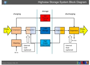
Compression Cleaning High Grade Cold Store Hot Thermal Store
Refrigeration StorageLAIR Evaporation Expansion Power
Out Power In Air In Air Out charging storage discharging External Cold (oponal) External Heat (oponal)
Figure 2. Conceptual model of Highview LAES system.
In developing its LAES systems, Highview has chosen to adopt a hybrid approach involving aspects of the adiabatic and isothermal CAES systems to remove the requirement for a fuel source as well as improving efficiency.
3. Highview LAES system
Highview’s LAES system can be described as a thermo-mechanical system where the energy is stored in thermal form, but its extraction and charging is carried out by mechanical means.
In summary, inlet air is compressed, dried and cleaned and the heat of compression stored (in hot water or thermal oil for later use on the power recovery cycle). The compressed air is expanded in a modified Claude cycle refrigerator (whose performance is enhanced by the cold recycled from the evaporation part of the cycle) and the resulting condensate, liquid air, stored in low pressure insulated tanks.
When the stored energy is required, the liquid air is pumped to high pressure and vapourised (the resultant high grade cold being stored for later use in the liquefaction cycle). The regasified air is then heated with the stored heat from the compression cycle and expanded in a multi stage process gas expander with inter-stage reheating, which drives the generator.
The storage of heat and high grade cold permits this part of the cycle to interface with other processes which may have similar process conditions and thereby present opportunities for efficiency enhancements.
© Highview Enterprises Limited, 2012
Figure 3. System PFD of Highview’s Pilot Plant.
prospect of improved efficiency from the liquefier. Similarly, waste heat from a host process (for example exhaust heat from landfill gas engines) could be used to provide further heating of the stored air which would offer additional power per stored kg of air, thereby presenting improved efficiency.
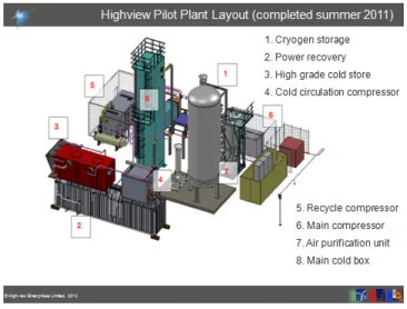
Highview has proved its cycle at pilot scale; its 300kW pilot plant has been operating since 2011. A simplified process flow diagram of Highview’s pilot plant is shown in the diagram below. Note that in this system, the heat of compression is rejected through a cooling system however, the cold captured from evaporation of liquid air is captured in a high grade cold store and recycled to enhance the liquefier performance.
A photograph of the pilot plant and a diagram showing its component parts are also shown so the physical configuration can be seen.
4. Performance
In general, LAES performs better at larger scale; turbo machinery is more efficient and the standing losses (thermal leakage) from the storage tanks are lower. In addition, the specific cost of systems is lower at larger scale, improving the system economics (dealt with separately later).
The key indicators for storage system performance usually relate to: Energy density; AC to AC round trip efficiency; flexibility and response time; and standing losses.
Figure 4. Photograph of Highview’s Pilot Plant at Slough Heat and Power.
• AC to AC round trip efficiency – Discharging energy/charging energy. For a stand-alone unit at suitable scale (see below) efficiencies in excess of 60% are possible. Efficiencies >70% can be achieved with the right combination of host site offering waste cold and/or heat.
• Response time – provided that the cryogenic feed pump(s) are kept cold and the turbine oil warm, starting the power turbine to synchronisation is usually achievable in around 1 minute with loading rate a function of the turbine size (the pilot plant can fully load in around 1 minute). On the charging side, provided the liquefier is cold (which usually means it has been at operating temperature within 24 hours) starting takes <20 minutes – although the compressors will be loaded shortly after starting. If the liquefier has not been operated recently and is at room temperature, a cooling cycle could take around 2 hours or more, depending on the liquefier size.
• Standing losses – A liquid air system loses its stored energy through heat leakage into the main cryogenic storage tank which causes boil-off. This is counteracted with insulation and losses of less than 0.2% per day are readily achievable based on established industrial gas industry equipment. This makes LAES comparable to self-discharge rates of battery technologies. [2]
5. Scale
Figure 5. Diagram showing the main components of the Highview Pilot Plant.
• Storage Tanks – using LNG storage technology would permit very large quantities of liquid air to be stored. 200,000m3of cryogenic storage using LNG technology would be capable of storing
in the 17–24 GWh range of power (depending on the energy density available – see above). As a result, tanks are not seen as a limiting factor in deployable scale.
• Liquefier – a typical, readily available large scale liquefier would have a daily production capacity of about 2,000 tons per day of liquid air. Employing the relevant cold recycle systems integrated into the Highview design, this would have an electrical demand of around 17 MW. At present, the likely cheapest way to provide higher capacity would be to utilise multiple 2,000 ton trains. • Cryogenic Feed Pump – the required flow of liquid air for a 20 MW power turbine is in excess of
50 kg/s at>100 bar (indeed 200 bar is the long term target feed pressure). The LNG industry is a useful source of such pumps which are typically used in re-gasification terminals and flows in excess of that required for a 20MW expander at the target pressure are already available from a single pump.
• Power Turbine – standardised frame, multi-stage radial inlet designs are available up to around 20 MW in output, larger outputs are readily achievable by separating stages into individual machines. Significantly larger outputs are available through the use of axial geometry which requires a degree of adaptation to suit the application.
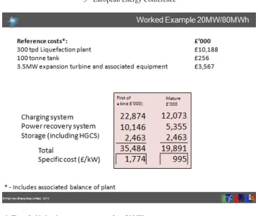
Figure 6. First of a kind and mature system costs for a 20 MW system.
5.1 Summary system using available equipment
Charging
5×2, 000 tpd liquefier total demand∼83 MW (typical demand without cold recycle>170 MW) Storage
6,000 T liquid air storage (flat bottom low pressure cryogenic tank) Power Recovery
5×20 MW turbo expanders and associated cryo-pumps and heat exchanger packs, total net output 100 MW after allowing for cryo-pumping load.
6. Costs
Costing a liquid energy storage system is relatively straightforward, although the high degree of configurability (charging capacity/amount of storage/power output) means a “standard” system is hard to define. Having such flexibility in configuration does make the LAES technology highly adaptable to both application and market. In any event, Highview has adopted the approach of using a process plant scaling factor of exp (0.6) to estimate the cost of any plant based on reference costs for a given liquefier, storage capacity and power recovery system.
To estimate the cost of a mature system Highview uses a “learning rate” to estimate the benefits of repeat building the same configuration plant. The rate used in the example below is 17.5%, meaning a doubling in manufactured units, results in a 17.5% reduction in cost.
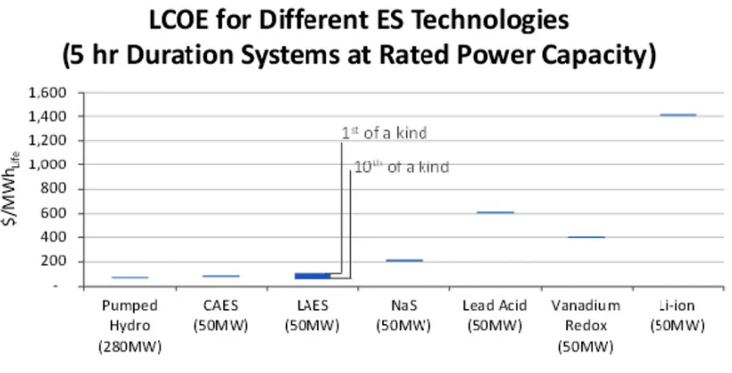
Figure 7. Lifetime levelised cost of energy for several storage technologies.
6.1 Costs when compared with other storage technologies
Comparing the costs of storage technologies can be very challenging given the very large range of functionalities, equipment lifetimes, performance and scales involved. To overcome this problem, EPRI and Sandia [3] have developed a metric which takes into account the various attributes and produces a single ‘levelised cost of energy’ over the entire duration of the analysis period. This could result in some battery systems having to be replaced several times during a 20 year study period, but does result in a comparison which is relevant for utilities, where equipment is expected to have a long life and allows for comparison with other utility equipment (e.g. fossil power plant and or transmission equipment).
The conclusions to be drawn from this comparison are as follows:
• The mechanically based systems are the lowest cost due in large part to their long lives. In addition, the LAES systems are very similar in cost to the compressed air systems (also note that difference in LCOE from first of a kind to 10thof a kind is small).
• The higher cost of the battery systems is attributable in large part to the need to replace the systems as they degrade over time.
• The cost of LAES systems is very competitive especially given the lack of geographical constraints.
7. Conclusions
Highview’s LAES represents a large scale energy storage system which is deliverable utilising technology which is available today with existing non-combustion based compressor and expander technology at its heart.
The independent nature of the major components allows for a high level of configurability, which in turn permits a level of system design flexibility which will allow its integration with a wide variety of host processes, resulting in efficiency benefits related to the use of waste heat and/or cold.
The nature of the equipment employed in the system is likely to result in a long system lifetime, which is compatible with the expectations of the utility based nature of its applications.
References
[1] Stover, Rehfeldt, Alekseev, Stiller, Liquid Air Energy Storage: A flexible and widely applicable medium term large scale energy storage concept (Linde and Hitachi) (2013)
[2] Susan M. Schoenungand WilliamV. Hassenzahl, Long vs Short-term Energy Storage Technologies Analysis, Sandia Report(2003) Available on-line at:http://prod.sandia.gov/ techlib/access-control.cgi/2003/032783.pdf
![Figure 1. First generation compressed air and equivalent liquid air energy storage systems [1].](https://thumb-us.123doks.com/thumbv2/123dok_us/8191420.1368109/2.482.60.427.56.343/figure-generation-compressed-equivalent-liquid-energy-storage-systems.webp)