Injection of Balanced Three-Phase Currents with Fuzzy Control of
Three-Phase Bidirectional Csc under Unbalanced Grid Voltage
Condition
K.R.Rakesh Babu & Sridhar Babu Gurijala
1M.Tech(student), St. Martin‟s Engineering College, Dhullapally, Secunderabad, Telangana. 2AssociateProfessor, St. Martin‟s Engineering College, Dhullapally, Secunderabad, Telangana.
ABSTRACT-In this paper proposes a control of three phase bidirectional current source converter with fuzzy controller is proposed to inject the balanced currents in different conditions. In this paper we are using the fuzzy controller compared to other controllers i.e. The fuzzy controller is the most suitable for the human decision-making mechanism, providing the operation of an electronic system with decisions of experts. In this topology, under a balanced grid voltage condition, the DC-link inductor current can be regulated over a wide range from zero to rated value while the AC-side current has low harmonic distortion. The AC-side currents will be unbalanced due to the presence of a negative sequence component. The FLC comprises of three parts: fuzzification, interference system and defuzzification. Various control loop structures for the operation of voltage source converter under unbalanced grid voltage conditions are reported in the literature. However, use of similar control loop structures for CSC may lead to unstable operation. Therefore, a control scheme to inject balanced three- phase currents into the AC grid under an unbalanced grid voltage condition is proposed in this paper. The stability of the proposed control scheme is studied using a small-signal model of the converter.
Index Terms—Bidirectional, Current source converter, DC-AC, Stability, Unbalanced grid.
INTRODUCTION
The voltage source converter (VSC) is a converter topology that is commonly used to interface a DC microgrid with a utility AC grid that has a bidirectional power flow capability. However, reliability of this converter is low due to the presence of a large electrolytic capacitor across the DC-link. Film capacitor based VSC has lower energy density, higher cost and/or employ additional active ripple reduction circuit. Further, VSC requires an additional DC-DC boost converter to interface a low-voltage DC microgrid with an AC grid.
A single-stage, current source converter (CSC) topology shown in Fig. 1 is proposed for battery charging/ discharging, and DC motor drive application. The use of this converter topology as an interface between the DC microgrid and the utility AC grid is suggested. The presence of single-phase loads, and unsymmetrical faults cause unbalance in grid voltages at the distribution level. These unbalanced grid voltages result in a second harmonic pulsation in the power, voltage and current on the DC-side of the converter.
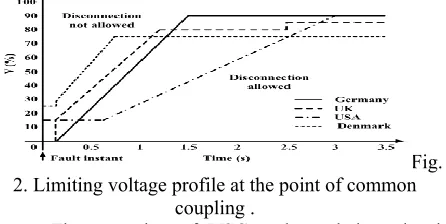
Fig.1. Bidirectional current source converter. Under such condition, the converter would trip if one of the phase currents exceeded the rated value. This may cause system instability and cascaded failure of the power system if the generation or load on the DC-side is significantly high. Therefore, the recent grid codes have made it mandatory that the converter stays operational if the grid voltage is above the limits shown in Fig. 2.
Fig. 2. Limiting voltage profile at the point of common
coupling .
The operation of VSC under unbalanced grid voltage condition is well reported in the literature. The control strategies reported in are based on the dual-frame controller: one controller in the positive and the other in the negatively rotating synchronous reference frames. In these schemes, the control target is either to maintain the active power constant or balance the grid currents. In it is proposed to inject zero sequence current into the grid, using a four-leg inverter. In positive and negative sequence modulation indices with appropriate phase angles are generated for a CSC interfacing a superconducting magnetic energy storage system with an unbalanced grid.
• In the proposed control strategy the negative sequence current component is eliminated from the grid current. • The effectiveness of the proposed control scheme is tested based on the percentage unbalance in the grid currents, grid current THD, peak-to-peak ripple in the DC-link current, current stress and voltage stress on the devices at various unbalance levels in the grid voltages. • A small-signal model of the CSC is developed .it is useful to evaluate the stability of the conventional and the proposed control loops.
THREE-PHASE BIDIRECTIONAL CURRENT SOURCE CONVERTER
The three-phase, bidirectional current source converter topology is shown in Fig. 1. This converter is a combination of a three-phase CSI, and a three-phase, three-switch current source rectifier (3SW-CSR). It has two broad modes of operation, namely, inverter and rectifier.
Inverter mode: Switches S1 to S6 constitute the
three-phase CSI. These switches provide the forward path for the DC-link inductor current iDC. Switches S1, S2 and S3 are known as upper group switches, while S4, S5 and S6 are known as the lower group switches. There are nine valid switching states, as given in Table I. The space vector diagram is shown in Fig. 3.
Fig. 3. CSI and 3SW-CSR space vectors..
Table 1
Converter Switching States: Inverter Mode Of Operation
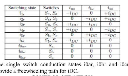
Rectifier mode: Switches Sa to Sc constitute the
3SWCSR. These switches provide the reverse path for iDC. At any instant, at least one switch conducts. Current iDC is controlled using the SVM technique. There are nine valid switching states, as given in Table II and shown in Fig. 3.
Table 2
Converter Switching States: Rectifier Mode Of Operation
The single switch conduction states i0ar, i0br and i0cr provide a freewheeling path for iDC.
CONTROL STRATEGY
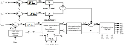
Fig. 4 shows the block diagram of the control strategy to regulate the DC-link inductor current. The phase angle information of the AC grid voltage is obtained using a three phase lock loop (PLL). The current references i∗ d and i∗ q are then transformed from a synchronous to a stationary reference frame. Magnitude and angular position of the reference current space vector |i ∗| and γ respectively, are calculated using the stationary frame reference currents i∗ α and i∗ β. The modulation index m is calculated by dividing the reference current space vector magnitude |i ∗| by the actual DC-link current iDC, as shown in Fig. 4.
Fig. 4. Block diagram of the control scheme to regulate the
DC-link inductor current.
The modulation index m and the angular position γ are fed to the converter SVM block. This block computes the active time periods of the switching states, and generates the gate signals.
CONTROL OF THE CONVERTER UNDER UNBALANCED GRID VOLTAGE CONDITIONS
In this section, possible control loop structures are evaluated under unbalanced grid voltage conditions.
No compensation during unbalanced grid voltage conditions
The converter draws/injects pulsating active and reactive powers from/to the grid. The instantaneous active power p (reactive power q) can be represented as a summation of a constant value Po (Qo) and two orthogonal, second harmonic oscillating signals having peak values Pc and Ps (Qc and Qs) as:
𝑝 = 𝑃𝑜+ 𝑃𝑐cos 2𝜔𝑡 + 𝑃𝑐sin 2𝜔𝑡 (1) And
In this case, although the average value of iDC is the same as its reference value, it has a second harmonic pulsation, proportional to the pulsation in the active power. Hence, it can also be represented as a summation of a constant value IDC and two orthogonal, second harmonic oscillating signals having peak values Idcc and Idcs as,
𝑖𝐷𝐶= 𝐼𝐷𝐶+ 𝐼𝐷𝐶cos 2𝜔𝑡 + 𝐼𝐷𝐶sin 2𝜔𝑡 (3)
Fig. 5. Nature of various control loop signals under an unbalanced grid voltage condition.
Fig. 5 shows the nature of various control loop signals under such operating condition. The presence of second harmonic pulsation in e, i∗ d and |i ∗| can be observed. Therefore, |i ∗| can also be represented as a summation of a constant value I∗ and two orthogonal, second harmonic oscillating signals having peak values I∗ c and I∗ s as,
𝑖 = 𝐼∗ ∗+ 𝐼
𝐶∗cos 2𝜔𝑡 + 𝐼𝑠∗sin 2𝜔𝑡 (4) The equation for a grid current space vector can be written
as,
𝑖 𝑔= 𝑚𝑖𝐷𝐶𝑒𝑗 𝜔𝑡 +∅ (5) where ϕ is the power factor angle and m is,
𝑚 = 𝑖 ∗
𝑖𝐷𝐶 (6)
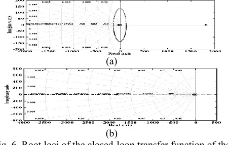
The stability of the control scheme shown in Fig. 5. It can be observed that this control scheme is stable when the proportional gain KP>0.6, and KP>0, for the inverter and rectifier modes of operation, respectively.
(a)
(b)
Fig. 6. Root loci of the closed-loop transfer function of the controller for the control scheme without unbalanced grid voltage compensation for (a) Inverter and (b) Rectifier
modes of operation.
Modified control scheme to inject balanced three-phase grid currents
It can be concluded from the above discussion that the uncontrolled second harmonic oscillation in the reference current space vector |i ∗| leads to a fundamental frequency
negative sequence and third harmonic positive sequence components in the grid currents. These oscillations in the control loop signals can be eliminated by filtering the iDC signal using a 100 Hz notch filter, as shown in Fig. 7. With this modification, (4) changes to,
𝑖 = 𝐼∗ (7) Using (3), (6) and (9) in (5) gives,
𝑖 𝑔 = 𝐼∗
𝐼𝐷𝐶+𝐼𝑑𝑐𝑐cos 2𝜔𝑡 +𝐼𝑑𝑐𝑠sin 2𝜔𝑡 ∗ 𝐼𝐷𝐶+ 𝐼𝑑𝑐𝑐cos 2𝜔𝑡 +
𝐼𝑑𝑐𝑠sin2𝜔𝑡𝑒𝑗𝜔𝑡+∅ (8)
Further simplification gives,
𝑖 𝑔 = 𝐼∗𝑒𝑗 𝜔𝑡 +∅ (9) It can be concluded from the above equation that the grid currents are perfectly balanced, and free from harmonic components.
Further, the stability of the modified control scheme shown in Fig. 7 is studied using the small-signal model of the converter. During the inverter mode of operation, at least one pole exists on the right hand side (RHS) of the imaginary axis for any finite value of KP .
Fig. 7. Block diagram of the modified control scheme to inject balanced three-phase grid currents under unbalanced
grid voltage conditions.
(a)
(b)
Fig. 8. Root loci of the closed-loop transfer function of the controller for the modified control scheme to inject balanced three-phase grid currents for (a) Inverter and (b)
Rectifier modes of operation.
PROPOSED CONTROL SCHEME TO INJECT BALANCED THREE-PHASE GRID CURRENTS
i∗ d. Instead, if it is the reference modulation index, then the ( 1 iDC ) term in the control loop can be avoided. The resulting block diagram is shown in Fig. 9.
Mathematical expression for the modulation index m
In (10), the first term represents the modulation index m. Therefore,
𝑚 = 𝐼∗
𝐼𝐷𝐶+𝐼𝑑𝑐𝑐cos 2𝜔𝑡 +𝐼𝑑𝑐𝑠sin 2𝜔𝑡 (10)
In the modified control scheme, the instantaneous value of m is calculated by solving the equation above by using instantaneous numerical values of its numerator and denominator terms.
After rearranging the terms, m can be expressed as,
𝑚 = 𝑀 + 𝑀𝑐cos 2𝜔𝑡 + 𝑀𝑐sin 2𝜔𝑡 + 𝑀𝑐cos 4𝜔𝑡 +
𝑀𝑐sin 4𝜔𝑡 + ⋯ (11)
The coefficients Mc4 and Ms4 are very small, because their expression contains the product of two AC terms in the numerator and the third power term of the average DC-link current in the denominator. Therefore, neglecting these terms, the expression for the modulation index m can be written as,
𝑚 = 𝑀 + 𝑀𝑐cos 2𝜔𝑡 + 𝑀𝑠sin 2𝜔𝑡 (12) In this equation, the value of M is determined using the control loop structure explained earlier, and shown in Fig. 9.
Fig. 9. Block diagram of the proposed control scheme to inject balanced three-phase grid currents under unbalanced
grid voltage conditions.
Closed-loop control of negative sequence currents
In the above equation, the second and the third terms correspond to the dq-axes fundamental frequency negative sequence currents. Therefore, these negative sequence currents can be expressed as
Fig. 10. Root locus of the closed-loop transfer function of the controller using the proposed control scheme to inject
balanced three-phase grid currents for inverter and rectifier modes.
𝑖 𝑞 = 𝑀𝐼𝑑𝑐𝑐
2 +
𝑀𝐶𝐼𝐷𝐶
2 sin ∅ − 𝑀𝐼𝑑𝑐𝑠
2 +
𝑀𝑠𝐼𝐷𝐶
2 sin (∅ −
𝜋
2) (13)
Therefore, the second harmonic oscillation required in order to obtain balanced grid currents, can be introduced in the modulation index m using two orthogonal signals [Mc cos(2ωt)] and [Ms sin(2ωt)], as shown in Fig. 9 Both the controllers have identical root loci as shown in Fig. 11. It can be observed that these controllers have stable operation for the condition 0<KP<0.1.
FUZZY LOGIC CONTROLLER
In FLC, basic control action is determined by a set of linguistic rules. These rules are determined by the system. Since the numerical variables are converted into linguistic variables, mathematical modeling of the system is not required in FC.
Fig.11.Fuzzy logic controller
The FLC comprises of three parts: fuzzification, interference engine and defuzzification. The FC is characterized as i. seven fuzzy sets for each input and output. ii. Triangular membership functions for simplicity. iii. Fuzzification using continuous universe of discourse. iv. Implication using Madman‟s, „min‟ operator. v. Defuzzification using the height method.
TABLE III: Fuzzy Rules
Fuzzification: Membership function values are assigned
to the linguistic variables, using seven fuzzy subsets: NB (Negative Big), NM (Negative Medium), NS (Negative Small), ZE (Zero), PS (Positive Small), PM (Positive Medium), and PB (Positive Big). The Partition of fuzzy subsets and the shape of membership CE(k) E(k) function adapt the shape up to appropriate system. The value of input error and change in error are normalized by an input scaling factor.In this system the input scaling factor has been designed such that input values are between -1 and +1. The triangular shape of the membership function of this arrangement presumes that for any particular E(k) input there is only one dominant fuzzy subset. The input error for the FLC is given as
E(k) = Pph (k )−Pph (k −1)
Vph (k )−Vph (k −1) (14)
Inference Method: Several composition methods such as Max–Min and Max-Dot have been proposed in the literature. In this paper Min method is used. The output membership function of each rule is given by the minimum operator and maximum operator. Table 1 shows rule base of the FLC.
Defuzzification: As a plant usually requires a non-fuzzy
value of control, a defuzzification stage is needed. To compute the output of the FLC, „height‟ method is used and the FLC output modifies the control output. Further, the output of FLC controls the switch in the inverter.The set of FC rules are derived from
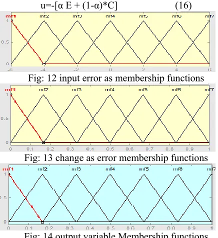
u=-[α E + (1-α)*C] (16)
Fig: 12 input error as membership functions
Fig: 13 change as error membership functions
Fig: 14 output variable Membership functions Where α is self-adjustable factor which can regulate the whole operation. E is the error of the system, C is the change in error and u is the control variable.
SIMULATION RESULTS
A 10 kVA converter interfacing a 415 V, 50 Hz, 3-phase AC grid with a 300 V DC microgrid is simulated using MATLAB\Simulink. The simulation parameters are given in Table III.
Fig. 15. Root locus of the closed-loop transfer function of the controller used to regulate the negative sequence currents .
TABLE 3
SIMULATION PARAMETERS
in Table III. Here, the DC microgrid bus voltage vBUS is emulated using a DC source.
FUZZY LOGIC CONTROLLER
In FLC, basic control action is determined by a set of linguistic rules. These rules are determined by the system. Since the numerical variables are converted into linguistic variables, mathematical modeling of the system is not required in FC.
Fig.16.Fuzzy logic controller
The FLC comprises of three parts: fuzzification, interference engine and defuzzification. The FC is characterized as i. seven fuzzy sets for each input and output. ii. Triangular membership functions for simplicity. iii. Fuzzification using continuous universe of discourse. iv. Implication using Mamdani‟s, „min‟ operator. v. Defuzzification using the height method.
TABLE III: Fuzzy Rules
Fuzzification: Membership function values are assigned
to the linguistic variables, using seven fuzzy subsets: NB (Negative Big), NM (Negative Medium), NS (Negative Small), ZE (Zero), PS (Positive Small), PM (Positive Medium), and PB (Positive Big). The value of input error and change in error are normalized by an input scaling factor. In this system the input scaling factor has been designed such that input values are between -1 and +1. The triangular shape of the membership function of this arrangement presumes that for any particular E(k) input there is only one dominant fuzzy subset. The input error for the FLC is given as
E(k) = Pp h (k )−Pp h (k −1)
Vp h (k )−Vp h (k −1) (17)
CE(k) = E(k) – E(k-1) (18)
Inference Method: Several composition methods such as
literature. In this paper Min method is used. The output membership function of each rule is given by the minimum operator and maximum operator.
Defuzzification: As a plant usually requires a non-fuzzy
value of control, a defuzzification stage is needed. To compute the output of the FLC, „height‟ method is used and the FLC output modifies the control output. Further, the output of FLC controls the switch in the inverter. In UPQC, the active power, reactive power, terminal voltage of the line and capacitor voltage are required to be maintained. The set of FC rules are derived from
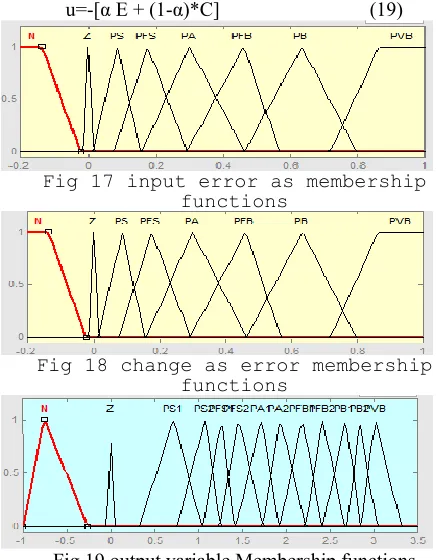
u=-[α E + (1-α)*C] (19)
Fig 17 input error as membership functions
Fig 18 change as error membership functions
Fig.19 output variable Membership functions Where α is self-adjustable factor which can regulate the
whole operation. E is the error of the system, C is the change in error and u is the control variable
Fig.20.Fuzzy logic controller in simulation.
Fig.21.Block diagram of simulation
No compensation during unbalanced grid voltage conditions
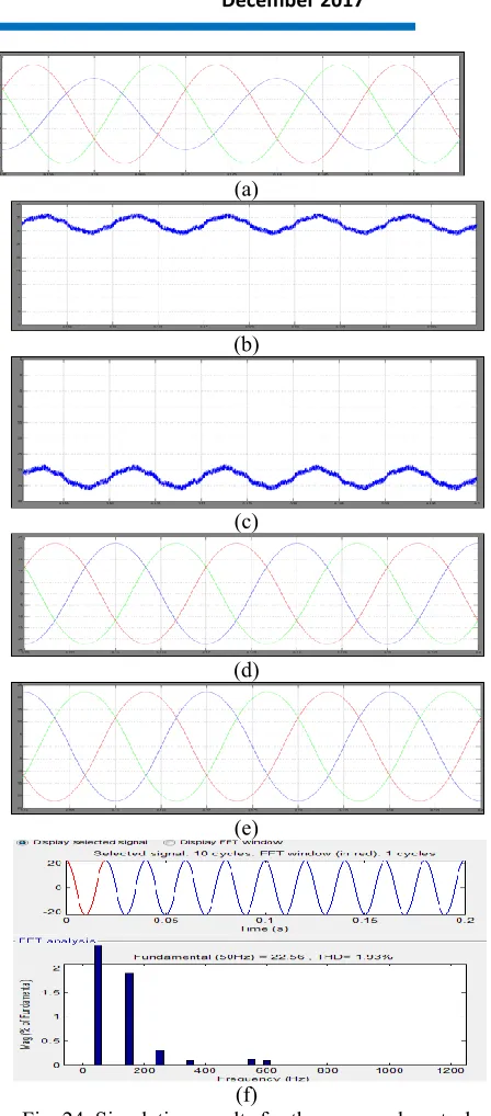
Figs.22(a) and (b) show the variation of iDC for the ramp changes in its reference value, in inverter and rectifier modes of operation, respectively. For these modes of operation, the grid phase voltage and current are shown in Figs.22(c) and (d). It can be seen that the system is capable of operating at a high power factor in both the modes.
(a)
(b)
(c)
(d)
Fig. 22. Simulation results:- Actual and reference DC-link currents for (a) Inverter (b) Rectifier modes of operation;
Grid phase voltage and current for (c) Inverter (d) Rectifier modes of operation under a balanced grid voltage
condition.
(a)
(b)
(c)
(d)
(e)
(f)
Fig. 23. Simulation results:- (a) Unbalanced three-phase grid voltages; DC-link current for (b) Inverter and (c) Rectifier modes of operation; Three-phase grid currents
for (d) Inverter and (e) Rectifier modes of operation; Harmonic spectrum of iag for (f) Inverter and (g) Rectifier
modes of operation.
Proposed control scheme to inject balanced three-phase grid currents
It can be seen from Figs. 24(b) and (c) that the DC-link current has second harmonic pulsation. In spite of this pulsation, balanced three-phase grid currents are obtained. This can be observed in Figs. 24(d) and (e). Figs. 24(f) and (g) show the harmonic spectrum of phase-a grid current iag for the inverter and rectifier modes of operation, respectively.
(a)
(b)
(c)
(d)
(e)
(f)
Fig. 24. Simulation results for the proposed control scheme:- (a) Unbalanced three-phase grid voltages;
(a)
(b)
(c)
(d)
(e)
(f)
(g)
(h)
(i)
(j)
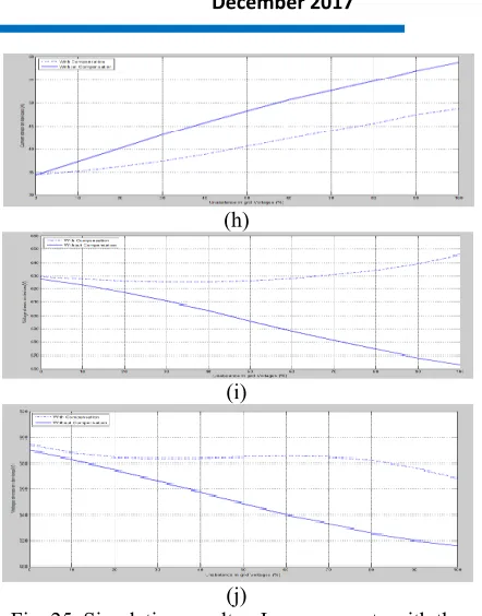
Fig. 25. Simulation results:- Improvements with the proposed control scheme: Three-phase grid current unbalance (a) Inverter mode (b) Rectifier mode; Grid current THD (c) Inverter mode (d) Rectifier mode;
Peak-to-peak ripple in DC-link current (e) Inverter mode (f) Rectifier mode; Current stress on devices (g) Inverter mode (h) Rectifier mode; Voltage stress on devices (i)
Inverter mode (j) Rectifier mode.
CONCLUSION
REFERENCES
[1] A. Lahyani, P. Venet, G. Grellet and P. J. Viverge, “Failure prediction of electrolytic capacitors during operation of a switchmode power supply,” IEEE Trans. Power Electron., vol. 13, no. 6, pp. 11991207, Nov. 1998. [2] J. M. Galvez and M. Ordonez, “Swinging Bus Operation of Inverters for Fuel Cell Applications With Small DC-Link Capacitance,” IEEE Trans. Power Electron., vol. 30, no. 2, pp. 1064-1075, Feb. 2015 [3] W. Huai, M. Ke and F. Blaabjerg, “Design for reliability of power electronic systems,” in Proc. IEEE Ind. Electron. Soc. Conf. (IECON), 2012, pp. 33-44. [4] E. Wolfgang, “Examples for failures in power electronics systems,” presented at ECPE Tutorial on Reliability of Power Electronic Systems, Nuremberg, Germany, Apr. 2007.
[5] W. Huai and F. Blaabjerg, “Reliability of capacitors for DC-Link applications in power electronic converters-an overview,” IEEE Trconverters-ans. Ind. Appl., vol.50, no.5, pp. 3569-3578, Sep.-Oct. 2014.
[6] D. Winterborne, M. Mingyao, W. Haimeng, V. Pickert, J. Widmer, P. Barrass and L. Shah, “Capacitors for high temperature DC link applications in automotive traction drives: current technology and limitations,” in Proc. IEEE European Power Electron. and Applicat. Conf. (EPE), 2013, pp. 1-7.
[7] A. Sannino, G. Postiglione and M. H. J. Bollen, “Feasibility of a dc network for commercial facilities,” IEEE Trans. Ind. Appl., vol. 39, no. 5, pp. 1499-1507, Sep. 2003.
[8] B. Mirafzal, M. Saghaleini and A. Kaviani, “An svpwm-based switching pattern for stand-alone and grid-connected three-phase single-stage boost inverters,” IEEE Trans. Power Electron., vol. 26, no. 4, pp. 1102-1111, Apr. 2011.
[9] P. P. Dash and M. Kazerani, “Dynamic modeling and performance analysis of a grid-connected current-source inverter-based photovoltaic system,” IEEE Trans. Sustain. Energy, vol. 2, no. 4, pp. 443450, Oct. 2011.
[10] B. Sahan, S. V. Arajo, C. Nding and P. Zacharias, “Comparative evaluation of three-phase current source inverters for grid interfacing of distributed and renewable energy systems,” IEEE Trans. Power Electron., vol. 26, no. 8, pp. 23042318, Aug. 2011.
K.R.RAKESH BABU
Completed B.Tech in Electrical &
Electronics Engineering in 2015 from JNTU, HYDERABAD and Pursuing M.Tech form St. Martin‟s Engineering College, Dhullapally, Secunderabad, Telangana. Area of interest includes Power Electronics. E-mail id:[email protected]
SRIDHAR BABU GURIJALA
Completed B.Tech in Electrical &Electronics Engineering from JNTUH University, HYDERABAD and M.Tech in Power Electronics from JNTUH, Hyderabad. And pursing Ph.D in K.L University &Working as Associate Professor in St. Martin‟s Engineering College, Dhullapally, Secunderabad, Area of interest includes multilevel convert topologies ,Facts devices, IPFC. Power quality, Voltage Source Converts.