Copyright to IJAREEIE DOI: 10.15662/ijareeie.2015.0407125 6720
Modelling and Simulation of Variable Speed
Squirrel Cage Induction Motor Drives
Khadim Moin Siddiqui1, Kuldeep Sahay2 , V.K.Giri3
Ph.D Scholar, Dept. of EE, Institute of Engineering & Technology, Lucknow, UP, India1
Professor, Dept. of EE, Institute of Engineering & Technology, Lucknow, UP, India2 Professor, Dept. of EE, Madan Mohan Malaviya University of Technology, Gorakhpur, UP, India3
ABSTRACT: In the present time, the variable speed induction motors are being popularized with efficient performance by using different PWM techniques. These kinds of drives are replacing D.C. motors and thyrister bridges day by day in the industries. In the past, Many Pulse Width Modulated (PWM) inverter fed induction motor models has been proposed by researchers and used in the various adjustable speed drives applications. But, the harmonics in the voltage, current and electromagnetic torque remains create problem in this type of drives. For minimizing harmonics, they used 5 and 7 level inverters. But, the 3-level inverter is being more popular and extensively being used in many power electronics and drives applications rather that 5 and 7 level inverters. Therefore, in this work, we have developed 3-level inverter fed squirrel cage induction motor model with better performance. In the present paper, the open and closed loop 3 level inverter fed induction motor has been proposed and developed in the latest MATLAB/Simulink environment. It has been observed that the closed loop PWM model gives better results as compare to open loop model with reduced harmonics. The direct torque control method has been used along with PWM inverter for induction motor controlling purpose.
KEYWORDS: Squirrel Cage Induction Motor, IGBT inverter, Pulse Width Modulation, Direct Torque Control, Modelling and Simulation, MATLAB/Simulink.
I.INTRODUCTION
Induction motors, especially Squirrel Cage Induction Motor (SCIM) are being widely used these days in the industries along with different PWM techniques for variable speed applications. This kind of drives are often used in the appliances, industrial control and automation; hence called workhorse of the motion industry[1,3]. The Induction Motor having some important advantages over other motors such as simple construction, high reliability and the availability of power converters based on efficient control strategies. Since, induction machines are made and used in largest number of applications due to their varied modes of operation under both under steady state and dynamic states[3,6,12].
Copyright to IJAREEIE DOI: 10.15662/ijareeie.2015.0407125 6721
The Pulse Width Modulation (PWM) inverters reduce harmonics in the output current as well as voltage by increasing the switching frequency and control the inverter output voltage as well as frequency by changing modulating wave. PWM inverters are more appropriate for speed control of induction motor instead of other techniques. The most popular technique is Sinusoidal PWM which is appropriate for linear modulation index upto 0.7855 only. Above this modulation index, SPWM produces more harmonics in output voltage and current. So, Space Vector PWM is suitable above 0.7855 modulation index. The main capability of SVPWM inverter is that it reduces THD as well as increases the basic value of inverter voltage. Consequently, induction motor works smoothly[6,8].
In the past, the 3 level PWM inverter fed induction motor drives has been proposed by various researchers. It has been observed that the THD in the current, voltage and electromagnetic torque was always the problem. Therefore, some researchers used 5 and 7 level inverters for minimizing harmonics. But, it has been seen that the 3 level inverter fed induction motor widely used in various applications[2,5,7,10]. Therefore, in this paper, our attempt is to minimize harmonics by using proposed models.
Since, the induction machine modelling has continuously attracted with the attention of researchers not only because such machines are made and used in largest number of applications but also due to their varied modes of operation both under steady state and dynamic states. In Electric Drive System elements, such machines is a part of the control system elements, which is to be controlled by the dynamic behaviour of Induction Motor (IM) then the dynamic model of IM has to be considered. The dynamic model considers the instantaneous effects of varying voltage/currents, stator frequency and torque disturbance[1,4].
In the present paper, the mathematical modelling of induction motor, open/closed loop induction motor fed PWM inverter model with THD analysis has been carried out for three level PWM inverter. This research paper is an attempt to minimize harmonics for 3 level PWM inverter by new proposed models.
II.
MATHEMATICAL MODELLING OF THE INDUCTION MOTORThe stator voltage on the q-axis and d-axis are given in equation 1 and 2. The equations from (1 to 7) come into the category of Electrical system.
qs
qs s qs ds
d
V
R i
dt
(1) Where,
qs
L i
s qs
L i
m
qrds
ds s ds qs
d
V
R i
dt
(2) Where,
ds
L i
s ds
L i
m
drThe rotor voltage on q-axis and d-axis are given in equation (3) and (4).
(
)
qr
qr r qr r dr
d
V
R i
dt
(3) Where,
qr
L i
r qr
L i
m qs(
)
dr
dr r dr r qr
d
V
R i
dt
(4) Where,
dr
L i
r dr
L i
m ds1
s s m
L
L
L
(5)1
r r m
L
L
L
(6)The Electromagnetic Torque is given in equation (7):
1.5 (
)
e ds qs qs ds
T
p
i
i
(7)The equations for the mechanical system are as shown below:
1
(
)
2
m
e m m
d
T
F
T
dt
H
Copyright to IJAREEIE DOI: 10.15662/ijareeie.2015.0407125 6722 m m
d
dt
(9)The abc-to-dq reference frame transformations applied to the Induction Machine phase-to-phase voltages are expressed by following equations:
2 cos 1 2 sin 3 qs ds V V
cos
3 sin
sin
3 cos
abs bcsV
V
(10) qr drV
V
=1
3
2cos
2sin
cos
3 sin
sin
3 cos
abr bcrV
V
(11)In the preceding equations, θ is the angular position of the reference frame, while β = θ - θr is the difference between
the position of the reference frame and the position (electrical) of the rotor. Because the machine windings are connected in a three-wire Y configuration, there is no homopolar (0) component. This also justifies the fact that two line-to-line input voltages are used inside the model instead of three line-to-neutral voltages.
The dq-to-abc reference frame transformations applied to the Induction Machine phase current are expressed by following equations. as bs
i
i
=cos
cos
3sin
2
sin
3cos
sin
2
qs dsi
i
(12) ar br
=cos
cos
3sin
2
sin
3cos
sin
2
qr dr
(13)cs as bs
i
i
i
(14)
cr ar br
i
i
i
(15)Where ias, ibs, ics are the stator currents in different phases. íar, íbr, ícrare the rotor current in different phases.
III. PROPOSED OPEN LOOP SIMULATION MODEL OF PWM INVERTER FED SQUIRREL CAGE INDUCTION MOTOR MODEL
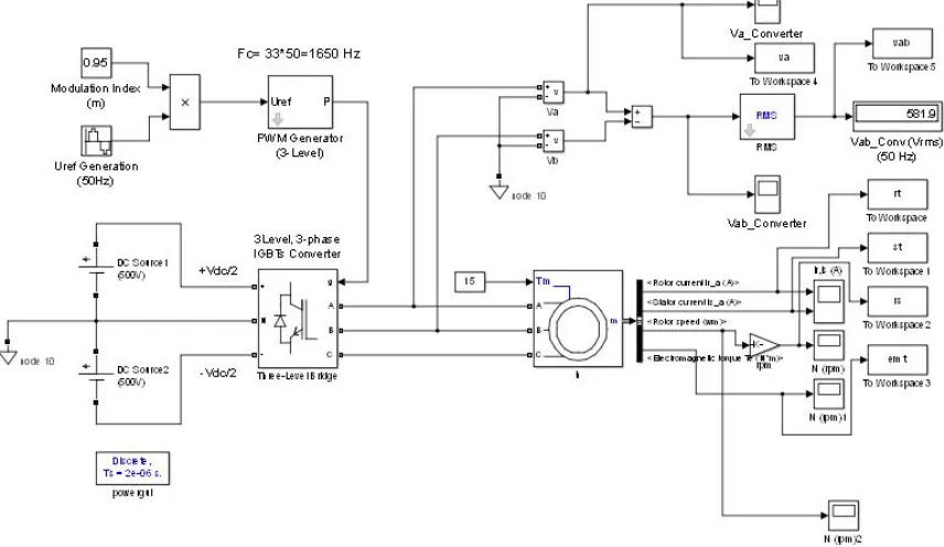
Variable speed controls of AC electrical machines make use by force-commutated electronic switches such as IGBTs, MOSFETs, and GTOs. Induction motors fed by pulse width modulation (PWM) voltage sourced converters (VSC) are nowadays gradually replacing the DC motors and thyristor bridges. With PWM, combined with modern control techniques such as field-oriented control or direct torque control, we can obtain the same flexibility in speed and torque control as with DC machines. Since, the IGBTs having superior characteristics rather than other power electronics switches in medium power applications. Therefore, in the present section we have developed an open and closed loop induction motor fed PWM inverter model with IGBT inverter in the Matlab/Simulink. This squirrel cage induction machine block can be operates in generator as well as motor mode. It depends upon the sign of mechanical torque(Tm).
If Tm is positive as shown in fig. 1, machine acts as motor and if Tm is negative it acts as generator. The applied full
load nominal constant mechanical torque at the machine's shaft is 15 Nm. The Simulink output block has one output but that contains 21 signals. We can de-multiplex these signals by the Bus Selector block provided by the Simulink library.
Copyright to IJAREEIE DOI: 10.15662/ijareeie.2015.0407125 6723
Hz). The Maximum time step has been limited to 10 µs. This is required due to the relatively high switching frequency (1650 Hz) of the inverter. It is recommended in [4] that the modulation factor mf be an odd multiple of three and that
the value be as high as possible. The PWM inverter is built entirely with standard Simulink blocks. The machine's rotor is short-circuited. Its stator leakage inductance L1s is set to twice its actual value to simulate the effect of a
smoothing reactor placed between the inverter and the machine. The motor is started from standstill condition. The speed set point is set to 1490 rpm under full load condition. This speed is reached after 0.1 s. it has been observed that the rotor and stator currents are quite "noisy," despite the use of a smoothing reactor. The noise introduced by the PWM inverter is also observed in the electromagnetic torque waveform. However, the motor's inertia prevents this noise from appearing in the motor's speed waveform.
Fig. 1 Open Loop Simulink Model of Squirrel Cage Induction Motor Model
The reference frame is used to convert input voltages (abc reference frame) to the dq reference frame, and output currents (dq reference frame) to the abc reference frame. We may choose among the following reference frame transformations:
i) Rotor reference frame (Park transformation)
ii) Stationary reference frame (Clarke or αβ transformation) iii) Synchronous reference frame
In our case, we have chosen stationary reference frame. The complete mathematical modelling and corresponding equations of the model has also been given earlier. The choice of reference frame affects the waveforms of all dq
variables. It also affects the simulation speed and in certain cases the accuracy of the results. The following guidelines are suggested in [4].
i) Use the stationary reference frame if the stator voltages are either unbalanced or dis-continuous and the rotor voltages are balanced (or 0).
ii) Use the rotor reference frame if the rotor voltages are either unbalanced or discontinuous and the stator voltages are balanced.
Copyright to IJAREEIE DOI: 10.15662/ijareeie.2015.0407125 6724
A pulse generator is used to control the inverter bridge. The efficient and common method is used for generating the PWM pulses. For generating the PWM pulses comparison of the output voltage to synthesize (50 Hz in this case) with a triangular wave at the switching frequency 1650 Hz (in this case). This method is implemented in the Discrete 3- phase PWM pulse generator block in the Matlab/Simulink. The line-to-line RMS output voltage is a function of the DC input voltage and of the modulation index m as given by the following equation:
VLL_Converter = m * Vdc/2 * sqrt(3) / sqrt(2)
VLL_Converter = m * Vdc * 0.6124
VLL_Converter = 0.95 * 1000 * 0.6124 = 581.8 V (16)
Therefore, the obtained line-to-line voltage converter value matches to obtained theoretical value. It may be observed from the fig.1. Therefore, we can say that the simulated model is working perfectly.
A. Simulation Results of Open Loop Model
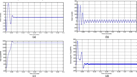
The simulation results in symmetrical or balanced supply (or called healthy mode) motor condition of the motor are as shown in fig 2. Four motor signatures are considered, those are stator current, rotor current, rotor speed and electromagnetic torque. In the healthy mode of the motor the slip is set at 1(s=1) and input mechanical torque is 15 N-m. It is observed from the obtained results, all the motor signatures are reached in the steady state condition after 0.1 seconds. The motor’s speed is reached (i.e. 1490 rpm) in the steady state after 0.1 sec. It has been observed that in the starting of the motor, the first peak of the stator current and electromagnetic torque waveforms has highest amplitude after that it is being decreased and reached in the stable condition. The rotor speed is controlled by V/f control method of the induction motor. The model is simulated for 0.5 sec for clear visualization of transient characteristics. Therefore, the transient characteristics of the motor may be clearly observed and analysed. The electromagnetic torque waveform shows that it is reached in the stable condition after 0.1 sec. It has also been observed that the strong oscillations of the electromagnetic torque at starting. If we zoom in on the torque in steady state, we will observe a noisy signal with a mean value 15 N-m, corresponding to the load torque at nominal speed. If we zoom on the three motor currents, we can observe that all the harmonics (multiple of the 1650 Hz switching frequency) are filtered by the stator inductance; hence we can say that the 50 Hz component is dominant.
(a) (b)
(c) (d)
Fig. 2 Results of Open Loop Simulink Model, (a) Stator Current, (b) Rotor Current, (c) Rotor Speed, (d) Electromagnetic Torque
0 0.05 0.1 0.15 0.2 0.25 0.3 0.35 0.4 0.45 0.5
-250 -200 -150 -100 -50 0 50 100 150 200 250
Time (seconds)
R
o
to
r
C
u
rr
e
n
t(
A
)
0 0.05 0.1 0.15 0.2 0.25 0.3 0.35 0.4 0.45 0.5
-150 -100 -50 0 50 100 150 200 250 300
Time (seconds)
S
ta
to
r
C
u
rr
e
n
t(
A
)
0 0.05 0.1 0.15 0.2 0.25 0.3 0.35 0.4 0.45 0.5
-200 0 200 400 600 800 1000 1200 1400 1600
Time (seconds)
R
o
to
r
S
p
e
e
d
(R
P
M
)
0 0.05 0.1 0.15 0.2 0.25 0.3 0.35 0.4 0.45 0.5
-200 -100 0 100 200 300 400 500 600 700 800
Time (seconds)
E
le
c
tr
o
m
a
g
n
e
ti
c
T
o
rq
u
e
(R
P
M
Copyright to IJAREEIE DOI: 10.15662/ijareeie.2015.0407125 6725
IV.PROPOSED CLOSED LOOP SIMULATION MODEL OF PWM INVERTER FED SQUIRREL CAGE INDUCTION MOTOR
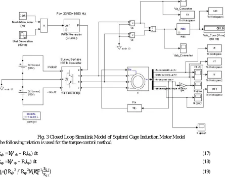
The closed loop induction motor fed PWM inverter Simulation model is as shown in fig. 3. It is simple open loop DC drive controlling an induction motor. The modern control techniques such as field oriented control or direct torque control technique can also be used with PWM inverter fed motor and can obtain same flexibility in speed and torque control like DC machines. The field control is an attractive control method but it has a serious drawback. It relies heavily on precise knowledge of the motor parameters. The rotor time constant is particularly difficult to measure precisely, and to make matter worse because it varies with temperature. The torque control method efficiently controls the induction motor. It estimates the stator flux and electric torque in the stationary reference frame and terminal measurements.
Fig. 3 Closed Loop Simulink Model of Squirrel Cage Induction Motor Model The following relation is used for the torque control method:
Ψds = ∫(Vds – Rsids) dt (17)
Ψqs =∫(Vqs – Rsiqs) dt (18)
φs=√ Ψds 2
+ Ψqs 2
≤ tan-1(Ψ
Ψ ) (19)
The Electromagnetic Torque is given as follows
Te= 1.5 p(Ψdsiqs – Ψqsids (20)
Copyright to IJAREEIE DOI: 10.15662/ijareeie.2015.0407125 6726
B. Simulation Results of Closed Loop Model
The simulation results of developed closed loop model are as shown in fig.4. The four motor current parameters are
(a) (b)
(c) (d)
Fig. 4 Results of Closed Loop Simulink Model, (a) Stator Current, (b) Rotor Current, (c) Rotor Speed, (d) Electromagnetic Torque
compared with obtained results by open loop model. These motor signatures are stator current, rotor current, rotor speed and developed electromagnetic torque. As, we have observed from the obtained results in the open loop that motor signatures have been reached in the steady state condition after passing through the transient time i.e. 0.1 sec. But, it has been observed in the closed loop model, for the same values transient time is get decreased. In the open loop transient time lost after 0.1 sec and in closed loop transient time lost before 0.1 sec. It can be observed from fig.4 (a-d) Therefore; we can say that the proposed torque control method can be used proficiently for the controlling of induction motor.
V. THD ANALYSIS of OPEN AND CLOSED LOOP MODEL
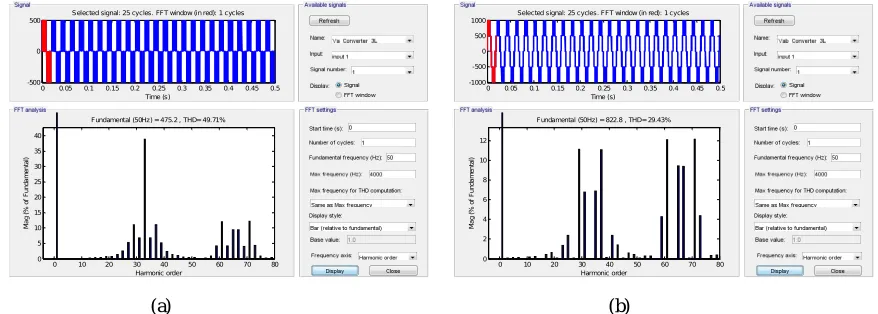
The Total Harmonic Distortion (THD) analysis for open and closed loop models has been discussed for its stator current and line-to-line voltages. The waveforms of Stator current and line-to-line voltages for 4KHz maximum frequency is as shown in fig. 5 and fig. 6 for open loop and closed loop respectively.
(a) (b)
Fig. 5 Total Harmonic Distortion in Voltages(open/Closed Loop), (a) THD in Voltage Va, (b) THD in Voltage Vab
0 0. 1 0.2 0. 3 0.4 0.5
-250 -200 -150 -100 -50 0 50 100 150 200 250 Time (seconds) < R o to r c u rr e n t (A )>
0 0.1 0.2 0.3 0.4 0.5
-150 -100 -50 0 50 100 150 200 250 300
Time (sec onds)
< S ta to r c u rr e n t( A )>
0 0. 1 0. 2 0. 3 0.4 0.5
-200 0 200 400 600 800 1000 1200 1400 1600 Time (seconds) R o to r S p e e d (R P M )
0 0.1 0.2 0.3 0.4 0.5
-200 -100 0 100 200 300 400 500 600 700 800
Time (sec onds )
< E le c tr o m a g n e ti c t o rq u e ( N *m )>
0 0.05 0.1 0.15 0.2 0.25 0.3 0.35 0.4 0.45 0.5 -500
0 500
Selected signal: 25 cycles. FFT window (in red): 1 cycles
Time (s)
0 10 20 30 40 50 60 70 80 0 5 10 15 20 25 30 35 40 Harmonic order Fundamental (50Hz) = 475.2 , THD= 49.71%
M a g ( % o f F u n d a m e n ta l)
0 0.05 0.1 0.15 0.2 0.25 0.3 0.35 0.4 0.45 0.5 -1000
-500 0 500 1000
Selected signal: 25 cycles. FFT window (in red): 1 cycles
Time (s)
0 10 20 30 40 50 60 70 80 0 2 4 6 8 10 12 Harmonic order Fundamental (50Hz) = 822.8 , THD= 29.43%
Copyright to IJAREEIE DOI: 10.15662/ijareeie.2015.0407125 6727
The THD in open loop stator current is more in comparison to closed loop but for the line-to-line voltages, THD is same in both the cases (open/close). It is because we are not controlling input line-to-line voltage here. Therefore, PWM inverter output voltage will be unchanged in open loop as well as closed loop. It has been observed that if the inverter is fed into induction motor then line voltage will be disturbed consequently rise in THD for line-to-line voltages but THD in the stator current will be less.
(a) (b)
Fig. 6 Total Harmonic Distortion in Stator Current , (a) THD in Open Loop Stator Current, (b) THD in Closed Loop Stator Current
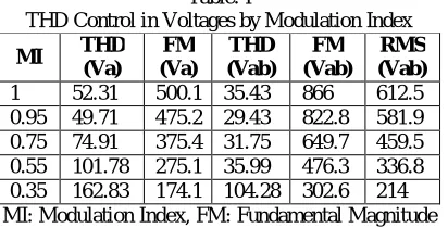
In this kind of drives, we may control line-to-line voltages by varying modulation index is as shown in the Table I. The THD of the line to line voltages and corresponding fundamental values are as shown in Table 2. The THD is lowest when modulation index is set 0.95.
Table. I
THD Control in Voltages by Modulation Index MI THD
(Va)
FM (Va)
THD (Vab)
FM (Vab)
RMS (Vab) 1 52.31 500.1 35.43 866 612.5 0.95 49.71 475.2 29.43 822.8 581.9 0.75 74.91 375.4 31.75 649.7 459.5 0.55 101.78 275.1 35.99 476.3 336.8 0.35 162.83 174.1 104.28 302.6 214 MI: Modulation Index, FM: Fundamental Magnitude
VI. CONCLUSIONS
In the present paper, an open loop and closed loop squirrel cage induction motor fed PWM inverter models have been developed and analysed its transient behaviour. However, the PWM inverter influences the motor performance and introduces disturbance into the main power line. But precisely designed interface system would be very useful in drive control applications. The extensive simulation has been carried out for 3 HP, 4 pole, 50 Hz induction motor and obtained simulation results has given ultimate solution for the wide range of speed control with reduced harmonics. It has been observed that the closed loop model has given better results as compare to open loop model with reduced harmonics. The torque control method has been used with PWM inverter for induction motor controlling purpose over field-oriented control technique due to its advantages discussed earlier. These models may be used in various power electronics and drives applications in industries. In future, these models may also be used in the different fault diagnosis purpose by advanced DSP based transformative techniques like Fast Fourier Transform and Wavelet Transform techniques.
REFERENCES
[1] Khadim Moin Siddiqui, Kuldeep Sahay and V.K. Giri, “Simulation and Transient Analysis of PWM Inverter Fed Squirrel Cage Induction Motor Drives”, i-manager’s Journal on Electrical Engineering, Vol.7, No.3, pp.9-19, Jan-March,2014.
[2] P. Thirumurugan and R.Preethi, “Comparison of Total Harmonic Distortion Different Levels of Inverter”, Journal of Electrical Engineering, Vol.14, No.1, pp. 263-270, 2014.
0 0.05 0. 1 0. 15 0.2 0.25 0. 3 0. 35 0.4 0.45 0.5 -100
0 100 200
Selected signal: 25 cycles. FFT window (in red): 1 cycles
Time (s)
0 10 20 30 40 50 60 70 80 0
5 10 15 20 25 30 35
Harmonic order Fundament al (50Hz) = 189.7 , THD= 11. 65%
M
a
g
(
%
o
f
F
u
n
d
a
m
e
n
ta
l)
0 0.05 0.1 0.15 0.2 0.25 0.3 0.35 0.4 0. 45 0.5 -100
0 100 200
Selec ted signal: 25 cycles. FFT window (in red): 1 cycles
Time (s)
0 10 20 30 40 50 60 70 80 0
5 10 15 20 25 30 35
Harmonic order Fundamental (50Hz) = 188.2 , THD= 11.39%
M
a
g
(
%
o
f
F
u
n
d
a
m
e
n
ta
Copyright to IJAREEIE DOI: 10.15662/ijareeie.2015.0407125 6728
[3] P.C. Krause, O. Wasynczuk and S.D. Sudhoff, Analysis of Electric Machinery, IEE Press, 1995.
[4] P.C. Krause, Simulation of Symmetrical Induction Machinery, IEEE Trans. Power Apparatus Systems, Vol.84, No. 11, pp.1038-1053, 1995. [5] Aparna Sharma, Abhijeet Singh and P.Yadav, “Analysis of 3 Level SVPWM based Open Loop and Closed Loop V/F Control of Induction
Motor”, International Journal of Engineering Research & Technology, Vol.4, No.4, pp.1362-1365, April, 2015
[6] Gaber EI-Saady, EI-Nobi A. Ibrahim and Mohamed Elbesealy, “V/F Control of Three Phase Induction Motor Drive with Different PWM Techniques”, Innovative Systems Design and Engineering, Vol.4, No.14, pp. 131-145, 2013.
[7] A. Ravi, P.S. Manoharan, J. Vijay Anand, “Modelling and Simulation of Three Phase Multilevel Inverter for Grid Connected Photovoltaic System”, In. ELSEVIER, August, 2011.
[8] A. Kwasinski, P.T. Krein, and P. L. Chapman, “Time domain comparison of pulse-width modulation schemes,” IEEE Trans. Power Electronics., Vol. 1, No. 3, pp. 64–68, September, 2003.
[9] G. Narayanan, V.T. Ranganathan, D. Zhao, and H. K. Krishnamurthy, “Space Vector Based Hybrid PWM Techniques for Reduced Current Ripple,” IEEE Trans. Ind. Electron, Vol. 55, No. 4, pp. 1614–1627, April, 2008.
[10] U.V. Patil, H.M. Suryawanshi, and M.M. Renge, “Torque Ripple Minimization in Direct Torque Control Induction Motor Drive Using Space Vector Controlled Diode Clamped Multi-Level Inverter,” Elect. Power Compon. Syst., Vol. 40, pp. 1060–1076, August 2011.
[11] I. Takahashi and T. Noguchi, “A new quick-response and high efficiency control strategy of an induction motor,” IEEE Trans. Ind. Appl., Vol. 22, No. 5, pp. 820–827, September 1986.
[12] Khadim Moin Siddiqui, Kuldeep Sahay and V.K. Giri, “Health Monitoring and Fault Diagnosis in Induction Motor- A Review”, International Journal of Advanced Research in Electrical, Electronics and Instrumentation Engineering, Vol. 3, No.1, pp.6549-6565, January, 2914.
ACKNOWLEDGMENT
Authors acknowledge Technical Education Quality Improvement Program Phase-II, Institute of Engineering & Technology, Lucknow for providing financial assistantship to carry out the research work.
BIOGRAPHY
Khadim Moin Siddiqui is teaching-cum research Scholar in the Department of Electrical Engineering, IET, Lucknow. He received his B.Tech degree in Electronics Engineering from Azad Institute of Engineering & Technology, Lucknow, India, in 2007, the M.Tech degree in Power Electronics & Drives from Madan Mohan Malaviya Engineering College,(presently Madan Mohan Malaviya University of Technology) Gorakhpur, India, in 2011. He has published 15 International Journal papers and 8 papers presented in the conferences. He has total 04 years of teaching experience in AIET Lucknow, NIIT, Bangalore & JNU, Jaipur. His research area of interest includes Electrical Machines, fault diagnosis and health monitoring.
Kuldeep Sahay, Ph.D. is associated with Institute of Engineering & Technology, Lucknow since 1996, where, he is presently Professor in the Department of Electrical Engineering, An Autonomous Constituent Institute of Uttar Pradesh Technical University, Lucknow. He has authored numbers of research paper in National and International Journal having good citation and published a book. His research interests are in the area of Mathematical Modeling of Energy Storage System, Integration of Renewable Energy System with Grid. Prof. Sahay for his overall contribution in research and academics has been awarded “Shikha Rattan Puraskar” and “Rashtriya Gaurav Award” by India International Friendship Society, New Delhi in 2011.