Wear 262 (2007) 684–692
A tribo-testing method for high performance cold forging lubricants
Gracious Ngaile
a,∗, Hiroyuki Saiki
b, Liqun Ruan
b, Yasuo Marumo
b aDepartment of Mechanical and Aerospace Engineering, North Carolina State University, Campus Box 7910, Raleigh, NC, USAbDepartment of Mechanical Engineering and Materials Science, Kumamoto University, 2-39-2, Kurokami 860-8555, Japan
Received 31 December 2005; received in revised form 2 August 2006; accepted 3 August 2006 Available online 15 September 2006
Abstract
A tribo-testing method based on inducing different deformation patterns at the tool–workpiece interface developed by the authors was used in rating the performance of high quality lubricants. Dies which can induce different levels of maximum surface expansion under localized rod drawing set up were used. The maximum local surface expansion induced ranged from 20 to 500%. The basic feature for this test lies under the assumption that the surface expansion is proportional to the lubricant thinning and breakdown at the tool–workpiece interface. The experimental set up is coupled with die heating facilities used to raise the temperature at the interface so that the influence of temperature on the performance of the lubricant is studied. The performance of several coating-based lubricants was studies under this method. One of the goals of screening the lubricant was to identify possible lubricant candidates for replacing zinc phosphate coating based lubricant for medium forging processes. The results have demonstrated that, the effectiveness of the lubricants varies considerably with changes in the maximum local surface expansion induced at the interface and the change in the interface temperature. Of the six lubricants studied, two lubricants based on calcium and sodium soap were found to be at the same performance level as the conventional zinc phosphate coating + metal soap.
© 2006 Elsevier B.V. All rights reserved.
Keywords: Tribo-testing; Lubricants; Cold forging; Surface evolution
1. Introduction
Lubricants play a key role in cold forging as they reduce the high frictional forces occurring at the tool–workpiece interface. Improved lubrication systems are needed, however, as they will help make net-shape production possible and affordable. The development of new lubrication systems needs to go hand in hand with the development of laboratory tests. A number of tests for cold forging processes have been developed to date. Critical reviews on these tests are given by Schey[1], Bay and Hansen[2], and Kawai et al.[3]. The problem pertaining to some of the tribo-tests developed to date is the failure to reproduce similar conditions to those occurring in the actual production environment. The failure of the tribo-tests can be caused by the deviation of the test characteristics from the actual plant tri-bosystem characteristics. Furthermore, the deviation of variables such as interface pressure, sliding velocity, interface tempera-ture, contact time, surface expansion, and the like can lead to a
∗Corresponding author. Tel.: +1 919 515 5222; fax: +1 919 515 7968.
E-mail address:gracious [email protected](G. Ngaile).
total failure of the tribo-test. In other words, the data obtained from the tribo-test may not be reliable particularly, if the defor-mation modes induced by the test have not been thoroughly studied.
In screening high performance lubricants for cold forging of complex components, more careful attention is needed. Most of these lubricants have good lubricity and it is not easy to distin-guish which lubricant is superior to the other, unless a tribo-test employed is sensitive enough to simulate the right deformation modes relevant to the specific forging process. An important aspect for a lubricant meant to be used in complex forging oper-ation is the level of adhesive strength of the lubricant to the parent material and the ability of the lubricant to follow surface extension without breaking down[4,5].
The aim of this paper is to present on the performance of sev-eral lubricants tested using the tribo-test method based on induc-ing different deformation modes at the tool–workpiece interface. In this method, tools of different geometrical profiles which can induce different levels of maximum local surface expansion are used. The basic feature for this test lies under the assumption that the surface expansion is proportional to the lubricant thinning and breakdown at the tool–workpiece interface.
Fig. 1. (a–c) Localized rod drawing experimental set up.
2. Methodology
The test is modeled such that, tools of different geometrical profiles are employed in order to induce different deformation patterns at the tool–workpiece interface under localized rod drawing setup. The tools employed vary from flat, sinusoidal, saw tooth, and multi-surface profiles as shall be discussed in Sec-tion2.3. The drawing force is supplied by a 500 kN Hydraulic cylinder and the die closing force being supplied by 200 kN hydraulic cylinder. Fig. 1shows the experimental test set up. The tooling can accommodate round rods of 1000 mm length and 20 mm diameter.
2.1. Determination of interface friction
The friction coefficient developed at the tool–workpiece interface under this test is given by the following formula.
μ= 1 C ×tan
arctan
Pv Pc
−φ
(1)
where,Pvis half the drawing force,Pcthe die closing force and φis the half die angle.Cis a correction factor for non-flat dies (Wavy dies) obtained by dividing the contact area of a non-flat die to that of a flat die of the same width. For flat diesC= 1. ThePvandPcare determined from Eqs.(2)and(3). The free body diagram showing the orientation ofPvandPccan be seen
inFig. 1b.
Pv=0.0059ε1−0.0181ε2−0.0528ε3 (2) Pc= −0.0601ε1−0.0467ε2−0.0017ε3 (3)
whereε1,ε2andε3are output strains in mV from the load cell. These expressions were obtained after conducting calibration of the load cell. The load cell was designed such thatPcandPvare linear function of strainsε1,ε2andε3shown in Eqs.(4)and(5)
[Fig. 1b and c].
Pv=a1ε1+a2ε2+a3ε3 (4)
Pc=a4ε1+a5ε2+a6ε3 (5)
To determine the values for the constantsa1,a2,a3,a4,a5, anda6, Eqs.(4)and(5)were arranged to form a functionfand this function was minimized as shown in Eqs.(6)and(7).
f =(a1ε1+a2ε2+a3ε3−Pc)2 +(a4ε1+a5ε2+a6ε3−Pv)2
(6)
∂ ∂ai
(a1ε1+a2ε2+a3ε3−Pc)2
+ (a4ε1+a5ε2+a6ε3−Pv)2
686 G. Ngaile et al. / Wear 262 (2007) 684–692
Fig. 2. Wavy die geometries.
where subscriptsi= 1, 2, 3, 4, 5 and 6. Calibration loads forPc andPvand their corresponding output strains were substituted in the above equations to solve for the constants.
2.2. Tool–workpiece interface temperature
In order to emulate realistic forging temperatures the setup is designed such that the dies are electrically heated to a controlled temperature. This is to embody similar thermal characteristics at the tool–workpiece interface as those occurring in an actual cold forging plant where the temperature normally reaches val-ues of about 200◦C[6,7]. As shown inFig. 1c, the die holder is designed with provisions for inserting heating coils. The desired tool–workpiece interface temperature which can be varied from room temperature to 300◦C is controlled by a control panel [Fig. 1a]. The load cell is provided with water jackets [Fig. 1c] where water is circulated to restrict the excessive heat transfer to the load cell. By controlling the volume flow rate of water in the cooling system, the temperature distribution at the load cell structure is kept below 25◦C. The major reasons for incor-porating the cooling system is to prevent any variation of stress due to temperature increase at the columns where strains are measured and also suppress any change in strain gauge char-acteristics which might be caused by the thermal loading. In order to record the temperature distribution at the interface and the surroundings a video thermal camera is employed [Fig. 1c]. Thermal couples are also embedded into the die holders to assist in measuring temperatures at some selected points.
2.3. Die geometry selection
The dies for the tribo-test are categorized in terms of the level of maximum local surface expansion they can induce at the tool–workpiece interface. As mentioned above, this method
employs dies with surface patterns ranging from flat, sinusoidal, saw-tooth, to multi-surface ones. The major die geometrical vari-ables are contour radii, pitch, root depth and the angle subtending the ridges. To determine the maximum local surface expansion induced by these dies, finite element (FE) simulation is used. Surface expansion values are highly dependent on deformation modes, part complexity and the material properties, particularly, the strain hardening index[8,9].Fig. 2shows examples of wavy dies.
2.3.1. FE modeling
2D FE simulations were carried out to study the local sur-face expansion as the dies pinch the material to a predetermined reduction. The simulations were carried out using the commer-cial FE software DEFORM. The FE simulations emulate the first stage during the localized rod drawing process. FE simulation for the second stage, i.e., drawing was not carried out. There-fore, the contribution of drawing to the surface expansion is not reported here. The FE simulations were conducted for Flat dies, Wavy-2 and Wavy-3 dies. For all the simulations a 12 mm diam-eter rod was pinched by advancing the dies from each side by 2 mm. The flow stress for the specimen wasσ= 800εnN/mm2. A quarter FE model with 3000 elements and a friction factor of
m= 0.10 (equivalent to∼μ= 0.06) was used for all simulations. To determine the influence of strain hardening on surface evolu-tion, three strain hardening coefficients,n= 0.06, 0.10 and 0.20 were used.Fig. 3shows the FE model for flat and wavy dies.
2.3.2. Surface evolution as a function of die geometry and material properties
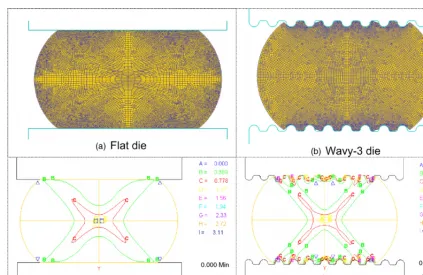
Fig. 3. (a–d) FE model, flat dies and wavy dies. maximum surface expansion of 25% is induced by flat dies.
Little variation of the local surface expansion from point A to point B is observed with flat dies. When Wavy-2 and Wavy-3 dies were used, completely different surface expansion distribu-tion patterns were observed. Wavy-2 dies exhibited a maximum local surface expansion of 220%, while Wavy-3 dies exhibited a maximum local surface expansion of 410%. The difference in the level of surface expansion for the two wavy dies is attributed to the die geometric differences shown in Fig. 2. The radius of the ridges for Wavy-2 and Wavy-3 are 0.6 and 0.4 mm, respectively. It is also observed that wavy dies exhibit two distinct regions; one region is dominated by surface expan-sion and the other region by surface contraction. The maximum surface contraction levels for Wavy-2 and Wavy-3 are −35 and−50%, respectively. It should be noted that the expansion
Fig. 4. Surface expansion distribution when strain hardening indexn= 0.06 is used.
peaks observed inFig. 4occur at the roots of the wavy formed part.
When the strain hardening exponent was changed from
n= 0.06 to 0.20, the overall magnitude of local surface expan-sion decreased for all the dies.Fig. 5shows surface expansion distribution profiles when n= 0.10 was used. With flat dies a maximum of local surface expansion of 20% is observed. Wavy-2 exhibited a maximum local surface expansion of 130%, while Wavy-3 exhibited a maximum surface expansion of 370%. The surface expansion distribution profiles forn= 0.20 are given in
Fig. 6, where maximum local surface expansions of 15, 110, and 270% were exhibited for flat dies, Wavy-2 and Wavy-3, respec-tively. The change in the local surface expansion with change in
688 G. Ngaile et al. / Wear 262 (2007) 684–692
Fig. 6. Surface expansion distribution when strain hardening indexn= 0.20 is used.
the strain hardening exponent implies that the difference in the materials properties may alter tribological characteristics. It can also be concluded that with the low level of local surface expan-sion induced by flat dies, it will be difficult to capture accurately the performance of cold forging lubricant since the lubricant will not be subjected to severe deformation modes typical of most cold forging of complex parts.
2.4. Test procedures
Six types of coating-based lubricants were tested for their performance. The main compositions of the lubricants are given inTable 1. Lub1 is a commonly used lubricant for cold forg-ing and is based on zinc phosphate coatforg-ing which is chemically combined with metal soap. The application/coating process for this lubricant involves a series of chemical baths. Lub2 and Lub3 contained only metal soap (calcium and sodium), however, Lub3 had more percentage of calcium than Lub2. Lub4 contained the same chemical compositions as Lub2, but with an additional of chlorine and fluorine. Lub5 and Lub6 had the same base chemi-cal compositions; however, the billets for Lub6 were dipped in a polymer liquid with anticipation that the polymer will increase lubricity.
The dies used in the tests were made from tool steel (JIS-SKD11) hardened to 700 Hv. Flat dies and Wavy dies were used in the test [Fig. 2]. The die surfaces were lapped to acquire a sur-face roughness of 1.5m RZ. The specimens used were made
Table 1
Lubricant test matrix
Lubricant composition
Lub1 Zinc phosphate coating + metal soap (calcium + sodium) Lub2 Calcium and sodium soap
Lub3 Calcium and sodium soap (higher Ca% than Lub2) Lub4 Calcium, sodium, chlorine, fluorine
Lub5 Phosphate + phosphate metal salt
Lub6 Phosphate + phosphate metal salt + polymer
Fig. 7. Influence of flat die on friction coefficient.
from two types of materials. These materials were low carbon steel (JIS-S15C) with a flow stress ofσ= 800ε0.1N/mm2 and JIS-SCM 435 with a flow stress ofσ= 904ε0.12N/mm2. The size of the specimens for low carbon steel was 12 mm diame-ter×1000 mm length while the size for specimens made from SCM 435 was 11.6 mm diameter×1000 mm length, and 19 mm diameter×1000 mm length.
In order to study the effect of temperature on the performance of lubricants, the experiments were conducted under four differ-ent die surface temperature conditions, i.e., room temperature, 150, 200 and 250◦C. To study galling and tool wear behav-ior, the weight and surface roughness of the dies before and after the experiment were measured. Furthermore, to study the lubricant film spread behavior, the lubricant chemical element compositions from the drawn specimens were analyzed by using scanning electron microscope coupled with energy dispersive spectroscopy.
3. Experimental results and discussion
3.1. Influence of die geometry on interface friction
Fig. 7shows the change in friction coefficient with stroke when the four lubricants: Lub1, Lub2, Lub3, and Lub4 were tested for their performance. In this case, 11.6 mm diameter specimens made from JIS-435 material were drawn using flat dies. A coefficient of friction of nearlyμ= 0.10 is observed with zinc phosphate stearate (Lub1) coated specimens. Friction coef-ficients ofμ= 0.11, 0.12 and 0.13 were attained for Lub2, Lub3 and Lub4, respectively. Comparing the performance of Lub2, Lub3 and Lub4 with the standard phosphate coating stearate lubricant (Lub1), an insignificant increase in the coefficient of friction is observed. Thus, one can conclude that all the four lubricants are equally good.
On the contrary, when wavy dies were used under similar experimental conditions, a significant difference on the perfor-mance of the four lubricants was observed as shown inFig. 8
Fig. 8. Influence of wavy dies (Wavy-3) on apparent friction coefficient.
observed. However, a marked increase in friction coefficient is observed for Lub4. Thus, by employing wavy dies it was pos-sible to clearly distinguish the level of effectiveness of the four lubricants. Lub4 was found to be the least effective among the four lubricants. An important observation is that the flat dies failed to clearly distinguish the level of effectiveness of the four lubricants. This failure is due to the low level of local surface expansion induced by flat dies. The FE simulation discussed in Section2.3demonstrated that flat dies can induce a maximum surface expansion of 25% while Wavy-3 dies could induce local surface expansion of 410%. This implies that when tribological data sought are to be transferred to a production line where com-plex components with different surface contours rather than flat surfaces are to be forged, then flat dies would not be the right choice for screening the lubricants.
There has been a considerable effort to formulate forging lubricants that can replace zinc phosphate coating based lubri-cation systems[10–14]. Though zinc phosphate coating + metal soap results in very low frictional shear stress, it contains toxic substances and poses potential health risks. Performance com-parisons of Lub2 and Lub3 against zinc phosphate has
demon-lubricity at elevated temperature. To test for this quality, Lub1, Lub5 and Lub6 were used. The die surface temperature was raised to 150, 200 and 250◦C by heating the dies.
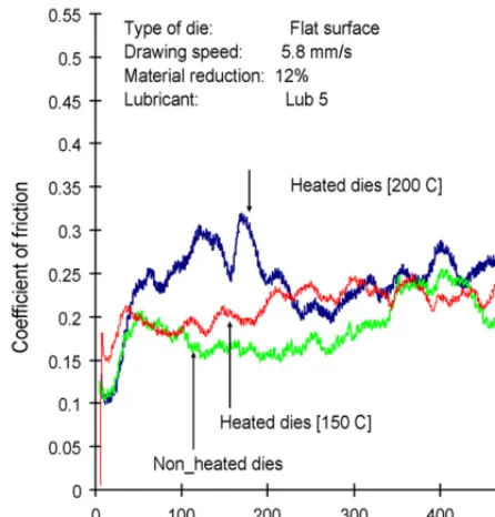
A standard conversion coating lubricant based on zinc phos-phate + metal soap [Lub1] was tested for its performance within the forging temperature range. As shown inFig. 9, the friction coefficient decreased with increasing die surface temperature. The average friction values attained at 150, 200 and 250◦C were, μ= 0.06, 0.05 and 0.04, respectively. The unique feature for this lubricant is the increase in lubricity with increasing temperature. InFig. 10, the variation of friction coefficient with interface temperature for Lub5 is shown. When non-heated dies were used, the coefficient of friction of aboutμ= 0.22 was observed. By raising the interface temperature to 150◦C, the friction coef-ficient slightly dropped to an average value of aboutμ= 0.20. However, when the interface temperature was set to 200◦C the friction coefficient rose to μ= 0.30. It can be noted that the change in friction with change in interface temperature is not significant with Lub5. This implies that, the lubricity level for this lubricant does not vary much within the forging temperature range.
On the contrary, when Lub6 was tested under similar experi-mental conditions, the lubricity level dropped significantly with increase in the interface temperature. When the die temperature was set to 150◦C the specimen failed just at the commencement
690 G. Ngaile et al. / Wear 262 (2007) 684–692
Fig. 10. Influence of die surface temperature on interface friction for Lub5.
Fig. 11. Influence of die surface temperature on interface friction for Lub6.
of the drawing experiment [Fig. 11]. Raising the interface tem-perature to 200◦C also led to the failure of the specimen. The friction coefficient rose as far asμ= 0.5 as compared to an aver-age friction value ofμ= 0.30 for the non-heated die condition. The basic chemical compositions for both Lub5 and Lub6 were
phosphate + phosphate salt. In Lub6, however, a liquid polymer was added on the assumption that the lubricity will be improved. The failure of Lub6 at 150◦C and 200◦is attributed to burning of the polymer material. In turn, the residue negatively affected the lubricant film resulting to an abrupt increase in the friction coef-ficient. The failure of Lub6, within the cold forging temperature range suggests that it is of paramount importance to include the temperature component in the lubricant screening methods.
3.3. Surface chemical analysis
Surface chemical analysis was done for specimens drawn using Lub1, Lub2, Lub3 and Lub4. The main objective was to observe the distribution of lubricant chemical element on the drawn specimen. Other objectives were to see the correlation of these distributions with the apparent friction coefficient values and to identify the lubrication regimes, namely full film lubrica-tion regime, mixed and seizure regime. The analysis was carried out under the assumption that specimen regions with low per-centage of lubricant chemical elements imply that the lubricant film has excessively thinned out, i.e., high percentage of Fe ele-ment from the bulk material is expected.
The surface chemical analysis was done using a scan-ning electron microscope coupled with energy dispersive spec-troscopy. As shown inFig. 12, the chemical analysis was done at the root and crest regions. These regions represent higher surface expansion and surface contraction, respectively, as demonstrated in the finite element analysis (seeFigs. 4 and 5).
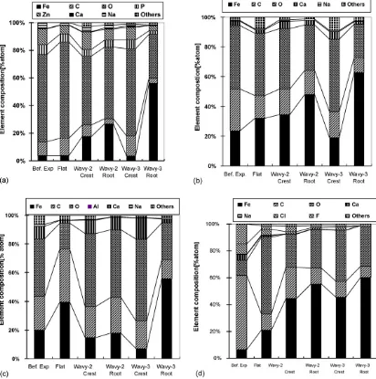
Fig. 13a shows the distribution of chemical elements for zinc phosphate stearate coating [Lub1]. It is observed that the distri-bution of chemical elements measured on a specimen drawn by flat die does not vary significantly with one measured on a spec-imen before the drawing tests. This implies that the deformation was under the full film lubrication regime. With specimens drawn by wavy dies, Wavy-2 and Wavy-3, a noticeable differ-ence in the distribution of chemical elements is observed. Large variations in the element distribution are observed on the spec-imen drawn by Wavy-3 dies. This is because the highest local surface expansion was induced by this die. A very low percent-age of Fe is observed at the crest region whereas at the root region the percentage of Fe is significantly high. This suggests that these regions were in different lubrication regimes. The chemi-cal element distributions also show a tendency for the lubricant to accumulate at the crest region. One factor contributing to the low level of Fe at the crest regions is the fact that the lowest pos-sible local surface expansion is attained at these regions. The FE simulations showed that crest regions were dominated by sur-face contraction. This implies that lubricant film thinning does not take place at these regions.
Fig. 13. Chemical element compositions for the four lubricants: (a) Lubricant 1 (Lub1), (b) Lubricant 2 (Lub2), (c) Lubricant 3 (Lub3), and (d) Lubricant 4 (Lub4).
From Fig. 8, we observed that friction values attained for both Lub2 and Lub3 were as low as that exhibited by the zinc phosphate lubrication system. The chemical element distribu-tions for flat and wavy dies show that Ca and Na chemical elements for Lub2 and Lub3 were still intact on the surfaces. It can also be noted that Lub3 exhibited slightly lower friction values than Lub1 and Lub2. This is attributed to the higher per-centage of Ca observed in the chemical composition analysis [Fig. 13c]. This suggests that a higher composition of Ca element on the coating has a positive effect on the effectiveness of the lubricant.
Fig. 13d shows the element distribution for Lub4. Though the element distribution pattern is similar to Lub1 and Lub2, in Lub4 a rapid increase in Fe is observed from Flat die to Wavy-3. This implies that the transition from full film lubrication regime to seizure regime was relatively faster than that of Lub1 and Lub2. This also justify why the highest friction coefficient was attained when Lub4 was used.
4. Conclusions
The tribo-test that can induce various deformation patterns developed by the authors has been presented. The dies for this test are chosen based on the level of local surface expansion induced. The local surface expansion and deformation modes are determined by the aid of the finite element method. The test has also provisions for heating dies to mimic realistic forging temperatures. This test was used to test several lubricants for cold forging application. The screened lubricants were aimed at replacing the zinc phosphate coating based lubrication system, particularly, for medium forging operations. The major conclu-sions drawn from this study are:
692 G. Ngaile et al. / Wear 262 (2007) 684–692 Lub4 was determined to be ineffective only when wavy dies
which represent complex forging processes were used. With flat dies which represent less severe forging operations, all lubricants; Lub1, Lub2, Lub3 and Lub4 seemed to perform equally the same.
• The study demonstrated that suitable tool geometries for the tribo-test can be designed based on prediction of the surface evolution of the part to be forged. This can be done with great accuracy using the finite element methods.
• The failure of Lub6 when heated dies were used implies that it is of great importance to test the lubricants within the typical forging temperature range. Also, in the initial development of tribo-tests, ways of acquiring realistic temperatures at the interface need to be considered.
• The surface analysis done using scanning electron microscope coupled with energy dispersive spectroscopy allows exam-ination of the distribution of lubricant chemical elements. This technique is helpful in foretelling the chemical elements that have a significant influence on performance, thus allow-ing the lubricant formulator to systematically and effectively select chemicals and improve lubricants in a short period of time.
• Lub2 and Lub3 were found to be potential candidates for replacing zinc phosphate coating for medium forging pro-cesses, particularly, those that induce deformation modes similar to the ones induced by the wavy dies used in this study. The advantage of Lub2 and Lub3 over zinc phosphate coat-ing is that no chemical baths containcoat-ing hazardous compounds were used. Therefore, the concerns pertaining to handling and disposal of waste were eliminated for Lub2 and Lub3.
Acknowledgments
The authors wish to acknowledge the support of Sumitomo Metal Industries Co., Ltd., for providing specimen materials and four lubricants, namely Lub1, Lub2, Lub3 and Lub4. Daido Chemical Industry Co., Ltd., for providing Lubricants 5 and 6. Acknowledgments should also go to, Y. Imamura, T. Hamada,
and T. Takayama, for their assistance with the experimental work and Cristina Bunget for conducting the finite element simulations.
References
[1] J. Schey, Tribology in Metal Working, American Societies for Metals, 1983, pp. 197–242.
[2] N. Bay, B.G. Hansen, Simulation of friction and lubrication in cold forging, in: Proceedings of Seventh International Cold Forging Congress, Birming-ham, 1995, pp. 55–62.
[3] N. Kawai, et al., Tribology in Metal Forming, Corona Publications, 1988, pp. 84–126 (In Japanese).
[4] H. Saiki, G. Ngaile, L. Ruan, Characterization of adhesive strength of phos-phate coatings in cold metal forming, ASME J. Tribol. 119 (1997) 667–671. [5] H.Y. Oie, Adhesion strength of phosphate coatings in cold forming, in: Proceedings of the Second International Cold Forging Congress, UK, 1987, pp. 147–153.
[6] W. Wibom, J. Nielsen, N. Bay, Influence of tool temperature on friction and lubrication in cold forging of steel, Wire 44 (1994) 275–281. [7] H. Saiki, G. Ngaile, L. Ruan, Y. Marumo, Evaluation of cold forging
lubri-cant under realistic forging temperature conditions, in: Advanced Technol-ogy of Plasticity Proceeding, vol. 1, Germany, 1999, pp. 377–382. [8] G. Ngaile, H. Saiki, L. Ruan, Y. Marumo, M. Ogura, Effect of local surface
expansion on the performance of coating-based lubricants in cold form-ing, in: Proceedings of the First International Conference on Tribology in Manufacturing Processes, Gifu, Japan, 1997, pp. 193–198.
[9] B. Bennani, N. Bay, Limits of lubrication in backward can extrusion: anal-ysis by the finite-element method and physical modeling experiments, J. Mater. Process. Technol. 61 (1996) 275–286.
[10] D. Schmoeckel, M. Rupp, More environment friendly cold massive forming—production of steel without zinc phosphate layer, in: Symposium “Latest Developments in Massive Forming”, In Fellbach near Stuttgart, 1997, pp. 183–200 (in German).
[11] L. Dubar, J.P. Bricout, C. Wierre, P. Meignan, New surface processes for cold forging of steels, Surf. Coat. Technol. 102 (1998) 159–167. [12] H. Saiki, G. Ngaile, Recent work on tribology in forging, in: Proceedings
of International Symposium on Advanced Forming and Die Manufacturing Technology, Pusan, Korea, September 1999, pp. 37–48.
[13] M. Takeuchi, F. Ikesue, N. Kashimura, Development of environmentally friendly lubricant with high performance and simple treatment for cold forging, Adv. Technol. Plast. 1 (1999) 383–390.