A Formal Framework for Specification-Based
Embedded Real-Time System Engineering
by
Martin Ouimet
B.S.E., Princeton University (1998)
S.M., Massachusetts Institute of Technology (2004)
Submitted to the Department of Aeronautics and Astronautics in partial fulfillment of the requirements for the degree of
Doctor of Philosophy at the
MASSACHUSETTS INSTITUTE OF TECHNOLOGY June 2008
@
Massachusetts Institute of Technology 2008. Allrxights reserved.Author ...
Department of Aeropautics and Ast onautics S M y 2 d, 2008 Certified by ... ...
I. Kristina Lundqvist Professor, Midlardalen University Thesis Advisor Certified by... .
R. John Hansman Professor, Massachusetts Institute of Technology
A Doc;pral Cpmm tee Chair Accepted by ... ... . ... ..
I Lid L. Darmofal
TSsC J.OW s WS Chairman, Department Committee on Graduate Students
OF TECHNOLOGY
AUG 0 12008
Certified by ... ,... ..- ...
Nancy A. Lynch
Professor, Massachusetts Institute of Technology
Thesis Supervisor
Certified by ...
...
,...
...
Heidi C. Perry
Director, The Charles Stark Draper Laboratory
Thesis Supervisor
Certified by...
57'
Nicholas Roy
Professor, Massachusetts Institute of Technology
A Formal Framework for Specification-Based Embedded
Real-Time System Engineering
by
Martin Ouimet
Submitted to the Department of Aeronautics and Astronautics on May 23rd, 2008, in partial fulfillment of the
requirements for the degree of Doctor of Philosophy
Abstract
The increasing size and complexity of modern software-intensive systems present novel challenges when engineering high-integrity artifacts within aggressive budgetary constraints. Among these challenges, ensuring confidence in the engineered system, through validation and verification activities, represents the high cost item on many projects. The expensive nature of engineering high-integrity systems using traditional approaches can be partly attributed to the lack of analysis facilities during the early phases of the lifecycle, causing the validation and verification activities to begin too late in the engineering lifecycle. Other challenges include the management of com-plexity, opportunities for reuse without compromising confidence, and the ability to trace system features across lifecycle phases. The use of models as a specification mechanism provides an approach to mitigate complexity through abstraction. Fur-thermore, if the specification approach has formal underpinnings, the use of models can be leveraged to automate engineering activities such as formal analysis and test case generation. The research presented in this thesis proposes an engineering frame-work which addresses the high cost of validation and verification activities through specification-based system engineering. More specifically, the framework provides an integrated approach to embedded real-time system engineering which incorporates specification, simulation, formal verification, and test-case generation. The frame-work aggregates the state-of-the-art in individual software engineering disciplines to provide an end-to-end approach to embedded real-time system engineering. The key aspects of the framework include:
* A novel specification language, the Timed Abstract State Machine (TASM) language, which extends the theory of Abstract State Machines (ASM). The TASM language is a literate formal specification language which can be applied and multiple levels of abstraction and which can express the three key aspects of embedded real-time systems - function, time, and resources.
* Automated verification capabilities achieved through the integration of mature analysis engines, namely the UPPAAL tool suite and the SAT4J SAT solver. The verification capabilities provided by the framework include completeness and consistency verification, model checking, execution time analysis, and resource consumption analysis.
* Bi-directional traceability of model features across levels of abstraction and lifecycle phases. Traceability is achieved syntactically through archetypical re-finement types; each rere-finement type provides correctness criteria, which, if met, guarantee semantic integrity through the refinement.
* Automated test case generation capabilities for unit testing, integration test-ing, and regression testing. Unit test cases are generated to achieve TASM specification coverage through the rule coverage criterion. Integration test case generation is achieved through the hierarchical composition of unit test cases. Regression test case generation is achieved by leveraging the bi-directional trace-ability of model features.
The framework is implemented into an integrated tool suite, the TASM toolset, which incorporates the UPPAAL tool suite and the SAT4J SAT solver. The toolset and framework are evaluated through experimentation on three industrial case studies
- an automated manufacturing system, a "drive-by-wire" system used at a major automotive manufacturer, and a scripting environment used on the International Space Station.
Thesis Supervisor: I. Kristina Lundqvist Title: Professor, Mdlardalen University Thesis Supervisor: R. John Hansman
Title: Professor, Massachusetts Institute of Technology Thesis Supervisor: Nancy A. Lynch
Title: Professor, Massachusetts Institute of Technology Thesis Supervisor: Heidi C. Perry
Title: Director, The Charles Stark Draper Laboratory Thesis Supervisor: Nicholas Roy
Acknowledgments
First and foremost, I would like to thank my advisor and thesis supervisor, Professor Kristina Lundqvist, for providing me with the guidance and with all the resources that I needed to succeed. I have a tremendous amount of admiration and respect for Professor Lundqvist as an intellectual leader, as a mentor, and as a friend. I would also like to thank Professor John Hansman for accepting the role of doctoral committee chair toward the end of my studies. Other members of my committee also deserve praise - Professor Nancy Lynch, Professor Nicholas Roy, and Heidi Perry -for taking time out of their busy schedules to guide me through the PhD process. Your time and feedback was invaluable. Professor Daniel Jackson also deserves mention due to his involvement in the general examination process.
On a research note, I would like to acknowledge JK Srinivasan, Professor Mikael Nolin, Professor Egon Bdrger, Gustaff Naeser, Yuri Gurevich, David Wang, Guillaume Berteau, and Matthieu Quenot, who have contributed directly and indirectly to the research included in this thesis. Furthermore, the Charles Stark Draper Laboratory deserves a special mention, since it has provided the funding for the project. Special thanks go out to Lauren Kessler and Heidi Perry who were instrumental to make this project a reality. I would also like to recognize Professor Charles Coleman for giving me the opportunity to explore various areas and for encouraging me to satisfy my intellectual curiosity.
On a personal note, I would like to give special consideration to my dear friends, who have withstood my intermittent emotional outbursts and my constant state of flux. Nicolas Dulac deserves special mention for being such a great friend. Michel Duranceau was also there when I needed him the most, even while 350 miles away. Etienne Parent was an awesome roommate and a true friend. Bart East and Jason Smyczek remained supportive, even though I wasn't always keeping in touch. Thank you to the East family and to the Duranceau family for continuing to be wonder-ful people. Yves Boussemart was always a source of positive attitude and occasional memorable incidents. Thank you to other friends -MV, TM, MAC, CG, HH, JL, LO,
NP, DW, CL, EP, JP, CL, MF, ... The MIT hockey team provided much needed en-tertainment and good times during my first years at MIT. The music crew also played an important role in my intellectual and emotional development - Rusty Scott, Vic-toria Chang, Elaine Kwon, Mark Kroll, Curtis Hughes, Mark Harvey, Tony Savarino, and Yoko Miwa. I would also like to recognize the wonderful ladies of the Boston area and beyond who, on various occasions, provided much needed emotional support and fantastic companionship to discover the wonderful nightlife of Boston and beyond. At the forefront, Wendy and Stella greatly contributed to my general well-being. WX, SJ, JQ, NT, MT, YJH, SSC, JC, AC, RC, V, LR, SD, CY, MM, MN, ... thanks for putting up with me, you are all awesome. Another thank you goes out to the fantasy baseball crew of New Jersey and Laval and to the fantasy hockey crowd of Montreal. The "Semi-Pro" crew, led by my uncle Michel, also deserves a wink.
Finally, a special "thank you" goes to my family who, at times, seemed more worried than my advisor about whether or not I would complete the PhD program. I have always maintained that if I could have half the heart of my father and half the courage of my mother, I would be extremely proud of who I am. Hopefully, I will get there some day. Thank you Gerard and Denise, you mean more to me than I can convey in a few lines. Thank you also to my brother, Patrick, my sister-in-law Annie, and their two sons Felix and Renaud. Your continuous support and distractions continue to be indispensable. Thank you also to my cousins Daniel and Richard. I promise that some day we will finally make it to Fenway Park. I am blessed to have a large extended family who is always radiant. Since they are too numerous to mention, I will not single them out individually; but kisses and firm handshakes go out to all the aunts, uncles, and cousins on both sides of my family.
Dear mom and dad, although I will probably never stop being a student in the figurative sense, I am convinced that the next time an acquaintance asks you what
your younger son does for a living, you will be extremely happy that you will no longer have to answer "student". Warm regards to all who helped make this a reality. With love,
Remerciements
D'abord et avant out, j'aimerais remercier mon superviseur et ma directrice de these, le Professeur Kristina Lundqvist, qui m'a guid6 dans ma recherche et qui m'a fourni toutes les ressources necessaires pour assurer mon succes. J'ai 6normement d'admi-ration et de respect pour le Professeur Lundqvist en tant que module intellectuel, en tant que conseillre, and en tant qu'amie. Je voudrais aussi remercier le Professeur John Hansman, qui a accept6 le r6le de chaire du comit6 d'evaluation durant la fin de mes etudes. Je me dois aussi de mentionner les autres membres de mon comit6 -le Professeur Nancy Lynch, -le Professeur Nicholas Roy, et Heidi Perry. Merci d'avoir pris le temps et d'avoir eu la patience pour me guider a bon port. Vos efforts et votre attention ont 6te grandement appr6ci&s. Le Professeur Daniel Jackson merite egalement mes remerciements dfi ' sa participation a l'examen general.
Du c6t6 de la recherche, je voudrais crediter JK Srinivasan, le Professeur Mikael Nolin, le Professeur Egon B6rger, Gustaff Naeser, Yuri Gurevich, David Wang, Guil-laume Berteau, et Mathieu Quenot, qui ont tous contribu6 a la recherche inclue dans cette these. De plus, le Charles Stark Draper Laboratory obtient une mention speciale, puisqu'il a subventionne ma recherche au cours de mes etudes au doctorat. Un gros merci
a
Lauren Kessler et ' Heidi Perry pour leur d6vouement. Je voudrais aussi remercier le Professeur Charles Coleman qui m'a donn6 l'opportunit6 d'explorer mes interits a ma guise et qui m'a encourage h satisfaire ma curiosit6 intellectuelle.Du c6t6 personnel, j'aimerais offrir ma profonde gratitude a mes chers amis, qui, a un moment ou un autre, ont tous dui subir les repercussions de mes sautes d'humeur et de mon incertitude constante. Nicolas Dulac a 6t6 de loin mon meilleur ami et com-pagnon spirituel a Boston. Meme s'il 6tait a 350 miles de Boston, mon meilleur ami de longue date, Michel Duranceau, a toujours su etre l1 pour me remonter le moral. Etienne Parent a et6 un ami exemplaire avec qui j'ai pu chialer plus souvent qu'a mon tour. Bart East et Jason Smyczek ont su apporter leur support, mime si je n'ai pas toujours 6t6 aussi communicatif que j'aurais dfi l'etre. Un gros merci a la famille East et a la famille Duranceau qui continuent d'&tre des gens extrimement chaleureux.
Yves Boussemiart a toujours 6t6 une source d'energic positive et d'occasionnels inci-dents m6rnorables. Merci aux autres amis - MV, TM, MAC, CG, HH, JL, LO, NP, CL2, EP, JP, DMW, ... J'ai 6galement decouvert la musique lors de mon sejour aux
6tudes -Rusty Scott, Victoria Chang, Elaine Kwon, Mark Kroll, Curtis Hughes, Mark Harvey, Tony Savarino, et Yoko Miwa - merci d'avoir ete' une source d'inspiration, merci de votre enseignement, et merci de votre encouragement. Je voudrais aussi mentionner ces divines demoiselles de Boston et d'ailleurs, qui ont su enflammer plus d'une soiree, tout en apportant un support emotionnel indispensable et une complicite remarquable, et avec lesquelles j'ai pu d6couvrir diffirents restos et bistrots de Boston et d'ailleurs. En tate de liste, Wendy et Stella ont grandement contribue a mon bien etre. WX, SJ, JQ, NT, MT, YJH, SSC, JC, AC, RC, V, LR, SD, CY, MM, MN, ...
merci de m'avoir tolire, vous etes sublimes. Je tiens aussi '. remercier la gang du pool de baseball du New Jersey et les gangs des pools de hockey et de baseball de Laval. Clin d'oeil aussi a la gang du "Semi-Pro", avec mon oncle Michel en tete.
Finalement, j'offre un remerciement special a ma famille, qui m'a support6 morale-ment et financieremorale-ment tout au long de mes 6tudes. J'ai toujours cru que si j'avais la moiti6 du coeur de mon pare et la moitie du courage de ma mere, je serais tres fier de l'homme que je suis devenu. J'espere y arriver un jour. Merci Gerard et Denise, vous Stes plus importants pour moi que je ne puisse le tUmoigner en quelques lignes. Merci aussi B mon frbre Patrick, B ma belle-soeur Annie, et a mes deux neveux Felix et Renaud. Merci aussi a mes cousins Daniel et Richard. Je vous promets qu'on ira au Fenway Park 6ventuellement. Je me compte tris chanceux d'8tre membre d'une grande famille etendue. Malheureusement, ils sont trop nombreux pour Rtre nommi s individuellement; tout de mime, j'offre baisers et poignees de mains viriles a toutes mes tantes, I tous mes oncles, et a tous mes cousins et cousines. Chers m6man et p6pa, mime si je ne cesserai probablement jamais d'8tre un 6tudiant au sens figur6, je suis convaincu que la prochaine fois ohi une connaissance vous demandera ce que votre plus jeune fils fait dans la vie, vous serez tres fiers de ne plus avoir a repondre "6tudiant". Merci a tous ceux et celles qui ont contribu6 ' mon succes. Avec amour,
Contents
1 Introduction 1.1 Motivations . . . . 1.2 Thesis Contributions . . 1.3 Relevant Publications . . . 1.4 Thesis Outline . . . . 1.5 Chapter Structure . . . . . 1.6 Notational Conventions . 1.7 Segue into Chapter 2 . . . 2 Background Information2.1 Real-Time Embedded Syste 2.1.1 The Nature of Time 2.2 Systems Engineering . . . Mc in Real-Time . . . . . .. • 2.3 Software Engineering ... 2.4 Formal Methods ...
2.5 Model-Based Software Engineering . . .
2.6 Modeling Languages ...
2.6.1 The Time Paradox: Incorporating 2.7 Analysis Engines ...
2.7.1 Model Checkers ... 2.7.2 SAT Solvers .... ... 2.8 Case Studies ... ... ...
2.8.1 The Production Cell . . . . 11 Systems . Time in High 27 27 28 29 30 33 34 34 35 35 39 41 42 45 46 48 50 54 54 56 57 58 . . . . . . . . . Level . . . .o . . . . . . ° . . ... • ... Models ... ... .o,,, .. ,..
2.8.2 Electronic Throttle Controller .. 2.8.3 Timeliner Script Executor .... 2.8.4 Motivations for the Case Studies 2.9 Segue into Chapter 3 ...
3 Framework Overview
3.1 Introduction ... 3.2 Related Work ... 3.3 Capabilities ...
3.3.1 Modeling and Simulation .... .
3.3.2 Static Analysis ...
3.3.3 Bi-Directional Traceability . . . . 3.3.4 Test Case Generation ...
3.4 Tool Architecture ...
3.4.1 Front-End Components ... 3.4.2 Back-End Components ... 3.4.3 3rd Party Engines ... 3.5 Segue into Chapter 4 ...
4 The Timed Abstract State Machine Specification Language
4.1 Related Work ... ... ...
4.1.1 Usability of Specification Languages ... .. 4.1.2 Abstract State Machines .. ...
4.1.3 The TASM Language ... ... 4.1.4 Other Specification Formalisms . ... 4.1.5 Light Switch Example . ...
4.2 The Timed Abstract State Machine (TASM) Language: Syntax 4.2.1 Basic ASM Specification . ...
4.2.2 Light Switch Example Version 1 . ... 4.2.3 Time .... ... ... 4.2.4 Resources ... ... 112 12 93 93 94 95 101 102 104 106 106 109 111
4.2.5 Light Switch Example Version 2 ... 4.2.6 Hierarchical Composition . ... 4.2.7 Light Switch Example Version 3 ... 4.2.8 Parallel Composition . ... 4.2.9 Light Switch Example Version 4 ...
4.3 The Timed Abstract State Machine (TASM) Language: 4.3.1 Update Set . ... ... .. . .. . . 4.3.2 T im e . .. . . . . . 4.3.3 Resources . ... . .. . . . .. 4.3.4 Light Switch Example Version 2 Revisited . . . 4.3.5 Hierarchical Composition. ...
4.3.6 Light Switch Example Version 3 Revisited . . . 4.3.7 Hierarchical Composition and Expressivity . . . 4.3.8 Parallel Composition . ...
4.3.9 Light Switch Example Version 4 Revisited . . . 4.3.10 Summary and Other Extensions ...
4.4 Relation to Timed ASM ... 4.5 Segue into Chapter 5 ...
5 Static Analysis
5.1 Functional Analysis: Completeness and 5.1.1 Related Work ...
5.1.2 Completeness ...
5.1.3 Consistency ... . .
5.1.4 Mapping to SAT ... 5.1.5 Example ...
5.2 Functional Analysis: Model Checking . 5.2.1 Mapping to UPPAAL . . . .
5.2.2 Example ... . . . . .
5.3 Execution Time Analysis ... 13 Consistency ... ... ... , . . . . . . . . . . . . . . ,. .. . . Semantics .... ,.. 113 113 116 117 118 118 121 121 122 124 125 129 131 135 139 141 146 149 151 151 153 154 157 160 161 165 166 167 168
5.3.1 Related W ork ... 170
5.3.2 Iterative Bounded Liveness ... . 171
5.3.3 Example: The Scheduling Problem . ... 177
5.4 Resource Consumption Analysis ... .. 182
5.4.1 Related Work ... . . .. ... 182
5.4.2 Approach ... ... ... . 183
5.4.3 Example ... ... 186
5.5 Segue into Chapter 6 ... . . ... 187
6 Bi-Directional Traceability 189 6.1 Related W ork ... ... 189
6.1.1 Syntactic Change Management . ... . . . 190
6.1.2 Refinement Theory ... . . ... 191
6.2 Concepts ... 193
6.2.1 Types of Refinements .. . ... . 195
6.2.2 Correctness Criteria . ... 200
6.3 Example ... ... ... 212
6.4 Segue into Chapter 7 ... 220
7 Test Case Generation 221 7.1 Related Work ... ... ... 221
7.1.1 Coverage Criteria ... ... 223
7.1.2 Abstract State Machines . ... ... ... 224
7.2 Test Case Generation Concepts ... .. 224
7.2.1 Definitions ... ... 225
7.2.2 Operations on Templates ... .. 227
7.2.3 Machines and Test Suites ... . 230
7.3 Unit Test Case Generation ... ... 231
7.3.1 Complexity Analysis ... .... 233
7.3.2 Example ... ... 234
7.4 Integration Test Case Generation ... . ... 235 14
7.4.1 Hierarchical Composition .... . . ... .. . . . 235
7.4.2 Complexity Analysis ... .... 239
7.4.3 Example ... ... ... ... . 239
7.5 Complete Test Case Generation Algorithm ... . . . . . 241
7.5.1 Test Sequences ... ... 244
7.6 Regression Test Case Generation ... .... .. . . . 245
7.6.1 Refinement Types ... ... ... 247
7.6.2 Test Case Execution ... ... 251
7.6.3 Complexity Analysis . . . . .. . .... . . . .. .. . . . . . 251
7.6.4 Example ... ... ... 252
7.7 Segue into Chapter 8 ... ... 256
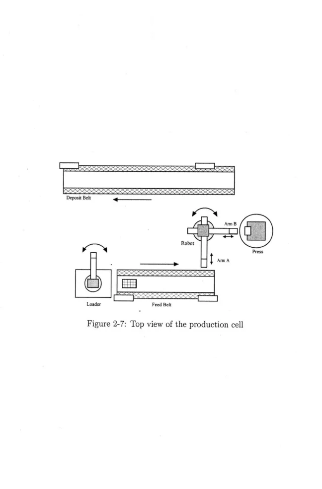
8 Case Studies 257 8.1 Production Cell . . . . .. ... ... .. .. . . .. .. . . . ... .. 258
8.1.1 M odel . . . .... . .. . . . . . 258
8.1.2 Functional Analysis ... ... ... 272
8.1.3 Execution Time Analysis ... ... 281
8.1.4 Resource Usage Analysis ... . . ... . 281
8.1.5 Test Case Generation . . . 283
8.1.6 Discussion . . . .... .. .. ... . . . . . . .. .. .. . 285
8.2 Electronic Throttle Controller: High Level M odel ... 286
8.2.1 M odel . . . .. . . . ... 290
8.2.2 Functional Analysis . ... . . . 292
8.2.3 Test Case Generation ... 301
8.2.4 Discussion ... .... ... ... 302
8.3 Electronic Throttle Controller: Tasking M odel . . .. . . . ... .. ... .. . . . 304
8.3.1 Model ... 307
8.3.3 Execution Time Analysis .
8.3.4 Test Case Generation ... ... 312
8.3.5 Discussion ... ... .. 312
8.4 Electronic Throttle Controller: Low Level Model ... .... ... . 314
8.4.1 Model ... ... ... 315
8.4.2 Traceability ... . ... 325
8.4.3 Functional Analysis . . .... .. 328
8.4.4 Execution Time Analysis ... .. 332
8.4.5 Resource Consumption Analysis . ... 335
8.4.6 Test Case Generation ... 337
8.4.7 Discussion ... ... ... 339
8.5 The Timeliner Script Executor: Plant Control System ... 341
8.5.1 M odel . . . 343
8.5.2 Functional Analysis ... . . . .... . 355
8.5.3 Execution Time Analysis ... . . 358
8.5.4 Test Case Generation .. . ... ... 361
8.5.5 Discussion ... 362
8.6 Segue into Chapter 9 ... ... . 363
9 Conclusion 365 9.1 Research Objectives and Contributions . ... 365
9.2 Framework Evaluation ... 368
9.2.1 The TASM Language ... ... ... 368
9.2.2 Static Analysis ... ... 370
9.2.3 Bi-Directional Traceability ... . 371
9.2.4 Test Case Generation .... . ... 372
9.2.5 Scalability . . . 373
9.2.6 Overall Limitations ... . ... 375 311
9.2.7 Lessons Learned ... 9.3 Opportunities for Future Research .
9.3.1 Language Extensions . . . .
9.3.2 Framework Features . . . . 9.3.3 Analysis Engines ... 9.4 Closing Thoughts ...
9.5 Segue into the Appendices ...
A TASM Language Reference
A.1 TASM Objects ... A.1.1 Specification ...
A.1.2 Project...
A.1.3 Environment ...
A.1.4 Main Machine Template . A.1.5 Function Machine ... A.1.6 Sub Machine ... A.1.7 Configuration ... A.2 Syntax ...
A.2.1 Notational Conventions.. A.2.2 Names ...
A.2.3 Types ...
A.2.4 Arithmetic Operators ... A.2.5 Logical Operators ... A.2.6 Context-Free Grammar .
A.3 Semantics ... ..
A.3.1 Operator Precedence . . .
A.3.2 Calling Convention . ...
A.3.3 Types ... .
A.3.4 Relation to Abstract State
... °... .. •**••° ... °°. .° • • . .° . .• . .. •°•..•• °...•°.•• .• . , • ,. . • •. *.•..,.•• . .• • . ...• . •. •°..••.•• Machines . . 383
...
383
. . . . . . 383 . . .. . . 384 . . .. . . 384 . . . . . . 384 . . . . . . 385 . .. . .. 385 . . . . 386 .. . . .. 386 . . . 386 .. . .. . 387 .. .. .. 387 . . . . . . 389 . . .. . . 390 . . . . . . 391 . . .. . . 400 . . . . . . 401 . . . . . . 401 . . .. . . 403 . . . . . . 403 A.3.5 Sugaring/Desugaring ... 17 376 377 377 378 379 382 382 . 404A.3.6 Resource definitions . A.3.7 Type definitions . . . A.3.8 Variables . . . . A.3.9 Rules . . . ... A.3.10 Execution Semantics
B Translating TASM Models to SAT
B.1 Preliminaries . ... B.2 Translation Algorithm ...
B.2.1 Function Machines . ...
B.2.2 Boolean and User-Defined Datatypes . B.2.3 Integer Datatypes ...
B.2.4 Constraints with Symbolic Right-Hand B.2.5 Complete Translation Algorithm. . . . B.3 Analysis . . . ...
B.3.1 Limitations ...
B.3.2 Complexity Analysis . ...
B.3.3 Intractability ...
Sides
C Translating TASM Models to UPPAAL 's Timed
C. 1 Preliminaries . . ... C.2 Translation Algorithm ...
C.2.1 Variables and Datatypes . . . ... C.2.2 Machines and Rules ...
C.2.3 Complete Translation Algorithm . . . . . C.3 Example . . . ...
Automata
D Production Cell TASM Model
D. 1 Environment . . . . ... D.2 Main Machines . ... . . . . . . . . . ... D.3 Function Machines ... . . . . . . . . . . . . . 404 404 405 405 407 409 409 410 410 411 414 417 417 418 418 419 420 423 423 425 425 426 430 431
435
437 439 444D.4 Sub Machines ...
E Electronic Throttle Controller TASM Model
E.1 High Level Model ... E.1.1 Environment E.1.2 Main Machines .. E.1.3 Function Machines E.1.4 Sub Machines . . .
E.2 Tasking Model ...
E.2.1 Environment . . .
E.2.2 Main Machines .. E.2.3 Function Machines E.2.4 Sub Machines . . E.3 Low Level Model ...
E.3.1 Environment .
E.3.2 Main Machines E.3.3 Function Machines
E.3.4 Sub Machines . . .
F Timeliner Plant Control System
F.1 Environment... ... F.2 Main Machines ... F.3 Function Machines ... F.4 Sub Machines ... TASM Model . . . .. • . . . .• ., . . . .• ., . ., .. . . . . ... . .. . 445 .,...°.°..
...
...
...
. . . .
.I
...
. . . . . . . . . . . . . . . . . . . . . . . . .. °.,....°,.. 457 457 459 461 466 470 475 476 477 480 481 486 488 491 497 499 501 503 505 509 509List of Figures
2-1 High level view of a mostly periodic reactive real-time system 2-2 Delay in system responding to an event of interest . . . ..
Systems engineering process [19] . . . . . V software lifecycle model [242] . . . . . Timed automaton describing the behavior 2-6 Sample task graph
Top view of the production cell . . . . High level Simulink model of the ETC ETC modes ...
ETC tasks and scheduler ... Timeliner script organization [61] . . . Timeliner plant application . . . .
. . . . . . . . . . 4 2 S . . . . . . . . . 4 4 of a lamp [24) .... ... 49 . . .. . . .. . .. . . .. . 5 1 . . . . . 59 . . . . . 67 . . .. . . .. . . .. . . .. 68 . .. . . . .. . .. . . .. . 69 . . . . . 7 2 . . . . . 74 3-1 Architecture of the TASM toolset
4-1 Light switch example . . . . 4-2 Hierarchical composition . . . . .
105 129
141 4-3 Time history of variable values and resource consumption
Timed automaton for Listing 5.1 . . . . Observer automaton ...
Task graph . . . .. .. . . . .. .. .. Timed automaton for the TASK1 main machine . . . . Timed automaton for the SCHEDULER main machine . .
168 175 178 180 181 2-3 2-4 2-5 2-7 2-8 2-9
2-10
2-11 2-12 5-1 5-2 5-3 5-4 5-55-6 Observer automaton to analyze schedulability . . . .
8-1 Top view of the production cell ... .. 258
8-2 Timed automaton for the feed main machine . ... 278 8-3 Observer automaton to verify the time needed to process 10 blocks 281 8-4 ETC m odes . . . . .... ... . ... .. . .. . .. .. . . ... 288 8-5 Observer automaton to verify the execution time of the servo task . 311 8-6 Simulink sliding mode controller to calculate driver throttle current 326 8-7 Traceability between different versions of the ETC model ... .. 327 8-8 Observer automaton to measure the end-to-end latency of the ETC for
the vehicle torque being over the critical threshold . ... 333 8-9 Automaton for the Scheduler main machine . ... 354 8-10 Observer automaton to measure the execution time of one pass of
Time-liner . . . 358 8-11 Observer automaton to measure the end-to-end latency of Timeliner
for a temperature drop ... . ... 360
C-1 Timed automaton for rule R, of Equation 2 . ... 427.
C-2 Timed automaton for Listing C.1 . ... . 428
C-3 Timed automaton for the "Else rule "and the "t := next" annotation 429 C-4 Timed automaton for a TASM machine with n rules ... 430 C-5 Timed automaton for the LIGHT_CONTROL machine ... . 432 C-6 Timed automaton to enforce the urgent channel for the else rule of
machine LIGHT_CONTROL ... ... 432
C-7 Timed automaton for the FAN_CONTROL machine .... ... . 433
C-8 Timed automaton to enforce the urgent channel for the else rule of
machine FANCONTROL ... ... 433
D-1 Top view of the production cell ... .. 435 182
List of Tables
2.1 Examples of sources of explicit quantitative time ... 40 2.2 List of actuators used in the production cell system ... 60 2.3 Behavior of actuators based on polarity . ... 61 2.4 List of sensors used in the production cell system . ... 61
2.5 Durative actions ... 62
3.1 Comparison of the proposed framework with other frameworks for em-bedded real-time systems engineering . ... . .. 82 4.1 Comparison of the features of the TASM language with other languages
for embedded real-time system specification . ... 105
4.2 Update set combination operators ... . 141
5.1 Maximum resource usage ... 187
5.2 Minimum resource usage ... ... 187
6.1 Truth table to verify the correctness criteria for the rule expansion
refinement between rule R1 and rules S11 and S12 . ... 215
6.2 Truth table to verify correctness the criteria for the rule expansion refinement between rule P1 and rules D1, D2, and D3 . . . 218
7.1 Pre and post state for sample test case template for Listing 7.1 .... 229 7.2 Coverage test case corresponding to the template of Table 7.1 . . . . 230 7.3 Template test suite for the machine of Listing 7.3 . ... 235 7.4 Template test suite for the machine of Listing 7.5 . ... 240
7.5 Template test suite for the machine of Listing 7.6 . ... 242
7.6 Template test suite for the machine of Listing 7.7 . ... 243
7.7 Test suite template for the machine of Listing 7.10 ... .. ... .... 254
7.8 Test suite template for the machine of Listing 7.7 ... ... . 255
7.9 List of test cases that need to be executed to cover the refinement . . 256
8.1 List of main machines used in the production cell model ... . 259
8.2 Number of rules for flattened main machines . . .. ... . . . .. . . 277
8.3 Completeness analysis results for the production cell model ... 279
8.4 Consistency analysis results for the production cell model ... . 280
8.5 Resource consumption analysis results for the production cell ... 283
8.6 Test case generation results for the production cell model ... . 284 8.7 Sample test case template from the test suite for the Controller main
machine ... ... .... . 285
8.8 Number of rules for flattened main machines for the high level ETC
model ... ... 298
8.9 Completeness analysis results for the ETC high level model ... 300
8.10 Consistency analysis results for the ETC high level model ... . 301 8.11 Test case generation results for the ETC high level model . .... .. 303 8.12 Sample test case template from the test suite for the CONTROLLER
main machine ... ... ... 303
8.13 Execution time for floating point operations for a PowerPC 405 (in
clock cycles) ... ... ... ... . .305
8.14 Timing properties for the ETC tasks . .. . ... ... . 305
8.15 Number of rules for flattened main machines.. . . .. .. . . . . . 309
8.16 Completeness analysis results for the ETC tasking model . .... . . 310
8.17 Consistency analysis results for the ETC tasking model ... .. ... 310
8.18 Test case generation results for the ETC tasking model . ... 312
8.19 Sample test case template from the test suite for the SCHEDULER
8.20 Truth table for the step expansion refinement between rule R1 of model To and rules R11 and R12 of model T1 . . . 317
8.21 Resource usage estimates for the ETC low level model . . . .. 325 8.22 Number of rules for flattened main machines . . . 330 8.23 Completeness analysis results for the ETC low level model ... . 331 8.24 Consistency analysis results for the ETC low level model ... . . 332 8.25 End-to-end latency analysis results for the ETC low level model . . . 335 8.26 Resource usage analysis results for the ETC low level model . . . 336 8.27 Test case generation results for the ETC low level model (part 1) . 337 8.28 Test case generation results for the ETC low level model (part 2) . 338 8.29 Sample test case template from the test suite for the TASKS main
machine ... ... ... 339
8.30 Duration of transitions (in us) between labels of Listing 8.25 . . . 345 8.31 Duration of transitions (in lis) between labels of Listing 8.26 . .... 345 8.32 Completeness analysis results for the Timeliner plant control system . 357 8.33 Consistency analysis results for the Timeliner plant control system . 357 8.34 Execution time analysis results for the WCET of one pass of Timeliner 359 8.35 Execution time analysis results for the BCET of one pass of Timeliner 359 8.36 End-to-end latency analysis results for the plant control system . . . 361 8.37 Test case generation results for the plant control system ... . 362 8.38 Sample test case template from the test suite for the Timeliner main
machine ... ... .. 362
A.1 Reserved keywords ... ... . 388
A.2 Operators ... .... . 392
A.3 Operator precedence ... . .... ... .. ... 402
C.1 Datatype translations ... ... .. . . . .. . . . 426 D.1 List of machines used in the production cell model .... ... . 436 E. 1 List of machines used in the high level ETC model . .... . . . 458
E.2 List of machines used in the tasking model of the ETC . ... 475 E.3 List of machines used in the low level ETC model (part 1) ... 486 E.4 List of machines used in the low level ETC model (part 2) ... 487 F.1 List of machines used in the Timeliner plant control system model . 502
Chapter 1
Introduction
This chapter serves as an "executive summary" of the work presented in this thesis. The chapter contains information about the motivations for the presented research, the contributidns of the research, the list of presentations, posters, technical reports and refereed publications related to the research, and the roadmap of the thesis. Each chapter in the thesis follows a template structure, as explained in Section 1.5.
1.1
Motivations
In modern society, software systems can be found everywhere, including in airplanes, in automobiles, and in consumer electronics. The proliferation of software increases the dependency on the correct functioning of software and yields a new set of chal-lenges in the engineering of software-intensive systems. The growing size and com-plexity of modern software systems exacerbates the difficulty of delivering reliable systems within aggressive budgetary constraints. In various engineering disciplines, the use of models has proven a viable approach to mitigate complexity through ab-straction [40]. However the use of models in the engineering of software is a relatively novel approach to building software systems. The use of models not only helps to control complexity, but if the models have formal underpinnings, the models can be used to automate certain engineering activities such as verification and test case generation.
The research presented in this thesis seeks to address five key challenges in the engineering of embedded real-time systems:
* The high complexity of modern software systems, by providing a model-based approach to software-intensive system engineering.
* The high cost of Verification and Validation (V & V) activities by leveraging the use of models to automate engineering activities.
* The challenges in using formal methods in an engineering context by providing a novel literate specification language and abstracting verification details in a push-button approach.
* The lack of integration between disparate models by providing bi-directional traceability across levels of abstraction.
* The lack of integration of the state-of-the art in individual disciplines by pro-viding an overarching engineering framework.
These five challenges form the base motivation for the research presented in this thesis. These challenges are addressed individually in subsequent chapters. In ad-dressing these challenges, the research presented in this thesis makes a number of research contributions in various areas. These contributions are outlined in the fol-lowing section.
1.2
Thesis Contributions
The research presented in this thesis makes five key contributions to address the challenges enumerated in the previous section:
* A new specification language for embedded real-time systems, the Timed Ab-stract State Machine (TASM) language, which extends the theory of AbAb-stract State Machines (ASM). The TASM language integrates the specification of func-tional and non-funcfunc-tional properties - function, time, and resources.
* A set of verification procedures for automated analysis of models, using generally available analysis engines. The procedures include the analysis of completeness and consistency, the analysis of execution time, and the analysis of resource consumption.
* An approach to traceability of system models that incorporates syntactic change and semantic integrity.
* A generic and extensible approach to automatically generate test cases for unit testing, integration testing, and regression testing.
* An integrated framework for modeling, simulation, verification, and test-case generation for embedded real-time systems.
* An integrated toolset implementing the capabilities of the framework.
1.3
Relevant Publications
The research presented in this thesis has led to presentations and poster sessions presented at the "Real-Time System Symposium (RTSS)" in December 2006 [189], at the "ARTIST Workshop on Tool Platforms for Embedded System Modeling, Analysis and Validation" of the "Computer-Aided Verification Conference (CAV)" in July 2007 [196], at the "Real-Time in Sweden Conference (RTiS)" in August 2007 [197], and at the "Asia-Pacific Software Engineering Conference (APSEC)" in December 2007 [204].
The presented research has also yielded a number of Technical Reports released through the Embedded Systems Laboratory (ESL) at the Massachusetts Institute of Technology [190, 195, 201, 202, 206]. A reference manual for the Timed Abstract State Machine (TASM) language [185], as well as a user guide for the TASM toolset [186] are also available through the Embedded Systems Laboratory [88].
The Timed Abstract State Machine language was presented to the real-time sys-tem community at the "Real-Time and Network Syssys-tems Conference (RTNS)" in
March 2007 [199] and to the ASM community at the "Abstract State Machines Work-shop (ASM)" in June 2007 [198]. A journal article about the TASM language is set to appear in Volume 14 of the Journal of Universal Computer Science (JUCS) in July 2008 [205]. A critical look on how time is treated in modeling languages, motivating the TASM approach to modeling time, was presented at the "Modeling in Software Engineering (MiSE) Workshop" of the "International Conference on Software Engi-neering (ICSE)" in May 2007 [194].
The case study involving the Electronic Throttle Controller (ETC) was presented at the "Critical System Development using Modeling Languages Workshop (CS-DUML)" of the "Model Driven Engineering Languages and Systems Conference (MoD-ELS)" in October 2006 [187] and was selected as one of two best papers to appear in Volume 4364 of Lecture Notes in Computer Science (LNCS) entitled "Models in Software Engineering" [188]. The analysis of TASM models using a SAT Solver was presented at the "Model-Based Testing Workshop (MBT)" of the "European Joint Conferences on Theory and Practice of Software (ETAPS)" in May 2007 [192] and appears in Volume 190 of "Electronics Notes in Theoretical Computer Science (ENTCS)" [193]. The TASM toolset was presented at the "Computer-Aided Verifi-cation Conference (CAV)" in July 2007 [200].
An overview of the framework will be presented at the "International Symposium on Quality Engineering for Embedded Systems (QEES)" [203], a symposium held jointly with the "European Conference on Model Driven Architecture Foundations and Applications (ECMDA)", in June 2008. A follow-up article will be submitted to the journal entitled "Software Tools for Technology Transfer".
1.4
Thesis Outline
This section provides an overview of the content of each chapter contained in this thesis.
This Chapter provides an "executive summary" of the thesis and should be read before other chapters.
* Chapter 2: Background Information
This chapter provides background information necessary to understand the ma-terial contained in the research. This chapter covers a wide range of topics such as information about real-time systems, software engineering, and descriptions of the analysis engines used to implement the framework. The reader is invited to browse sections of this chapter as needed.
* Chapter 3: Framework Overview
This chapter provides an overview of the capabilities of the framework as well as the tool architecture used in the implementation of the framework.
* Chapter 4: The Timed Abstract State Machine Specification Lan-guage
This chapter describes the Timed Abstract State Machine (TASM) Language, its syntax, semantics, and modeling facilities, including how time and resources are treated, hierarchical composition, and parallel composition. Throughout the chapter, illustrative examples are provided to depict the concepts as they
are introduced.
* Chapter 5: Static Analysis
This chapter presents the types of analysis that can be performed in the frame-work. The analysis procedures include completeness and consistency analysis, execution time analysis, and resource consumption analysis. This chapter also contains illustrative examples to demonstrate the analysis algorithms. The im-plementation of the analysis facilities, performed in the TASM toolset, are also described.
This chapter explains the bi-directional traceability capabilities of the proposed framework. The approach to traceability establishes a relationship between two or more TASM models and combines syntactic change management with notions of semantic equivalence for the models.
* Chapter 7: Test Case Generation
This chapter presents the automated test case generation capabilities of the framework for unit, integration, and regression test case generation. The re-gression test case generation strategy uses the traceability approach described
in Chapter 6. Examples and implementation details are also presented.
* Chapter 8: Case Studies
This chapter contains the results of the three case studies used to evaluate the research presented in this thesis - the production cell case study, an Electronic Throttle Controller (ETC), and the Timeliner Script Executor. The case studies are introduced in Section 2.8 but the models and analysis results are presented in Chapter 8. The complete TASM models for each case study are provided in the appendices.
* Chapter 9: Conclusion
This chapter provides a critical evaluation of the presented research, draws con-clusions for the thesis, and describes directions for possible future developments of the research.
* Appendix A: TASM Language Reference
This appendix contains the concepts involved with the implementation of the TASM language in the TASM toolset. These concepts include the complete Context-Free Grammar (CFG) for the TASM language and various implemen-tation topics such as operator precedence and typing.
This appendix contains the details of the mapping from the TASM language to
SAT, for the purpose of static analysis, as explained in Chapter 5, and for test
case generation, as explained in Chapter 7.
* Appendix C: Translating TASM Models to UPPAAL
This appendix contains the complete mapping from the TASM language to
UPPAAL , for the purpose of timing analysis, as explained in Section 5.3. The mapping to UPPAAL is also used for model checking of functional properties.
* Appendix D: Production Cell TASM Model
This appendix contains the complete TASM model for the production cell case study, explained in Section 2.8.1 and studied in Section 8.1.
* Appendix E: Electronic Throttle Controller TASM Model
This appendix contains the complete TASM model for the electronic throttle controller for the case study, explained in Section 2.8.2 and studied in Sec-tion 8.2, in SecSec-tion 8.3, and in SecSec-tion 8.4.
* Appendix F: Timeliner Plant Simulator TASM Model
This appendix contains the complete TASM model for the Timeliner case study involving the plant control system, explained in Section 2.8.3 and studied in Section 8.5.
1.5
Chapter Structure
Individual chapters in this thesis follow a common template. At the beginning of each chapter a paragraph explains the information contained in the chapter. The last section of each chapter is named "Segue into Chapter N" and provides a brief summary of the information provided in the current chapter and how it leads to the following chapter. All chapters follow this template except for the appendices. Unlike the thesis chapters, individual appendices do not follow a common pattern. However,
the first paragraph of each appendix contains a brief description of its content. The content of the appendices is summarized in Section 1.4. Appendices do not follow a linear progression and serve as a reference that can be read in any order.
1.6
Notational Conventions
In order to enhance the readability of the thesis, special fonts are used to clarify meaning in certain situations:
* Italic font is used for definitions and when referring to abstract syntax, such as the names of machines or the names of rules.
* Teletype font is used when referring directly to the concrete syntax of a model, such as a variable.
* "Quotation marks" are used to emphasize blocks of text that should be grouped together.
Furthermore, the listings for models expressed in the Timed Abstract State Ma-chine (TASM) language are expressed in teletype font.
1.7
Segue into Chapter 2
This chapter presented an "executive summary" of the content of the thesis. The following chapters expand on this summary. The next chapter, Chapter 2, provides background information about the topics covered throughout the thesis.
Chapter 2
Background Information
This chapter presents background information related to the concepts explained in the following chapters. The information contained in this chapter includes details about the types of systems targeted by the presented research, details about how the current work integrates into software engineering practice, information about the analysis engines used in the framework, and descriptions of the case studies used to evaluate the presented framework.
2.1
Real-Time Embedded Systems
The primary goal of a computer system is to provide value, as defined by a user of the system, by performing a set of functions. More specifically, a computer system must provide a correct response (output) based on a given stimulus (input). The concept of correctness is comprised of multiple facets such as functional correctness and non-functional correctness. The non-functional correctness of a computer system is defined through a set of requirements that the input-output behavior of the system must satisfy [853. The requirements describing the functional correctness of a computer system can be described through safety properties, that is, statements about behavior that should never occur, and liveness properties, that is, statements about behavior that should eventually occur [30]. All functional behavior of computer systems can be described in terms of safety and liveness properties [154].
While functional correctness is a critical aspect of all computer systems, certain types of systems also require that non-functional aspects of the system, such as tim-ing behavior, conform to strtim-ingent correctness criteria. The research presented in this work addresses the engineering of embedded real-time systems, a class of systems where non-functional properties are central to the system's value. More specifically, embedded real-time systems represent a special class of computer systems where time plays a critical role in the correctness of the system. In a real-time system, the system must not only produce a correct answer, but must also do so in an ade-quately bounded amount of time [58]. The amount of time under which the system must produce a response is termed a deadline. If a real-time system provides an answer after a deadline has elapsed, the system is said to have missed a deadline. With regards to correctness, the implications of missing a deadline depends on the type of system. Real-time systems fall into two categories - hard real-time systems, where missing a deadline is unacceptable, and soft real-time systems, where missing a deadline may be acceptable under certain circumstances, depending on performance requirements [155]. Nevertheless, time plays a critical role in defining the correctness of a real-time system since a correct answer provided too late can be as erroneous as
providing an incorrect answer [49]. The timing analysis provided by the framework does not make assumptions about whether the system being analyzed is hard or soft. The framework provides generic timing analysis to determine the best and worst case timing behavior, and it is up to the system behavior to decide whether the analysis results are acceptable for the system being engineered.
In practice, real-time systems are also typically reactive, meaning that they do not terminate, but are in continuous interaction with the environment, until the system is switched off. Reactive systems are different than transformational system, where the system terminates after producing an answer. In a reactive real-time system, the timing correctness of the system is defined as the absence of missed deadlines while taking into account the continuous interaction of the system with its environ-ment. The types of systems targeted by the proposed framework are of the mostly
the environment through sensors, makes a decision on what action the system should take based on the sensor values, and affects the environment by executing the action through an actuator. A sample loop for the systems targeted by the proposed frame-work is shown in Figure 2-1. It is important to note that which steps of the loop are executed at each iteration is implementation dependent. As will be described in the electronic throttle controller case study, the sampling of the state through sensors could be done at a lower frequency than, for example, the frequency of deciding on the action to be taken by the controller.
Sensors Actuators
Figure 2-1: High level view of a mostly periodic reactive real-time system In traditional real-time system theory, the concept of a deadline refers to the Worst-Case Execution Time (WCET) [89] also sometimes called the worst-case
com-putation time, that is, the maximum time that can elapse when an individual task or
an individual process executes [58]. In this research, the traditional WCET definition is made more general to include system properties. In the remainder of this work, the term WCET is used to denote the maximum amount of time that can elapse when the system completes a path between two states. The definition used in this thesis also stipulates that such a path can consist of any two states. In this definition, the notion
of state can include both the state of the engineering artifact such as the program
counter and values of system variables, and, the value of environment variables. This definition is more general than the traditional definition and can capture important concepts such as end-to-end latency all the while being able to express the traditional definition. End-to-end latency refers to the longest reaction time of a system to an environment stimulus, taking into account system properties such as environment
interaction, task interference, and delay in response. For example, in the loop of Figure 2-1, the value of an environment variable could change while the system is deciding on which action to take. Depending on the frequency of sensor readings, a significant delay could result in the system taking a corrective action since there could be a delay before the change is detected. Figure 2-2 shows a symbolic view of the time that can elapse between an event occurring and the system taking a corrective action. The verification problem to ensure that there are no missed deadlines can be summarized as:
dt = t2 - tl < Required Deadline
The response latency, dt, refers to how much time elapses between the event and the response. The proposed framework provides necessary facilities to calculate the maximum value of dt, for any event and action modeled. The Required Deadline is system-dependent and is provided by the performance requirements. It is also the responsibility of the system designer to decide on which course of action to take if the designed system does not meet the required deadline. The proposed system provides only the necessary modeling and analysis facilities. Additional definitions related to execution time are given in Section 5.3.
tl --- t2
event system takes occurs corrective action
Figure 2-2: Delay in system responding to an event of interest
Most real-time systems also fall into the category of embedded systems. Embedded systems represent a special class of real-time systems where the software system is not stand-alone, but is part of a larger system and must work with other components to achieve the system's goals [155]. Vehicle controllers, such as automotive electronics
and avionics, are typical examples of embedded real-time systems. In an embedded system, resources such as communication bandwidth and memory are typically limited and must be shared across multiple components. Consequently, the correctness of an embedded real-time system is also dependent on the resource usage being adequately bounded. In summary, for an embedded real-time computer system, the correctness of the system is defined in terms of three key aspects - functional correctness, timing behavior, and resource usage. These three aspects form the fundamental motivation of the modeling and analysis capabilities provided by the proposed framework.
2.1.1
The Nature of Time in Real-Time Systems
Since time plays an important role in defining the correctness of a real-time system, it is paramount to understand the role of time in the systems of interest. On a general and global level, the time axis is a monotonic function that is used to order events linearly according to some concept of progression [101]. A large body of research has been devoted to establish that a computer system satisfies a correct ordering of events [49]. This correct ordering of events, also called qualitative time, refers to the ordering of events with respect to one another and is not concerned with the temporal distance between events [212]. For example, in the well-known Simple Mail Transfer Protocol (SMTP), an acknowledgement message (ACK) shall not be received before a synchronization request (SYN) has been emitted. In other words, an ACK must occur after a SYN and never before. However, in real-time systems, timing correctness does not depend only on the ordering of events, but also depends on the numerical distance between events, a concept called quantitative time [155]. For example, in the SMTP protocol, after a SYN has been emitted, a timer is typically started while waiting for the ACK. If, after a prespecified amount of time, the ACK has not been received, the SYN sender might assume that the SYN request was lost. In such a situation, the precise amount of time between the SYN and the ACK is of particular importance, in addition to the messages occurring in the correct order.
Quantitative time appears in real-time system problems either explicitly or im-plicitly. Examples of where quantitative time appears explicitly include performance
Table 2.1: Examples of sources of explicit quantitative time
requirements, local clocks, timeouts, scheduling, the physics of the problem, and constraints of the components of the system. Examples of explicit instances of quan-titative time are shown in Table 2.1. Examples where time appears implicitly, as a side-effect, include software execution time and hardware execution time. List-ing 2.1 shows a brief example of software code, written in the Timeliner scriptList-ing language [61], borrowed from the Timeliner case study. The code represents a se-quence used to maintain cabin temperature between 20 and 25 Celsius degrees [238]. In order to determine how long this snippet of Timeliner code takes to execute, many other questions need to be answered. For example, the execution time of the script depends on:
* The properties of the execution platform * The semantics of the language
* The assumptions on the behavior of the environment
Once the code has been written and the system is implemented, these concerns can typically be addressed to a satisfactory degree of confidence. For example, in [62], precise timing measurements of each statement of the Timeliner language have been measured through laboratory experiments for a specific execution environment. How-ever, determining these execution times a priori remains a challenging endeavor.
Source Example
Requirements The data in the operator console shall be refreshed 10 times per second
Physics It takes approximately 5 sec-onds for a projectile shot straight up in the air at a ve-locity of 50 m/s to come to rest at its apogee
Components Pressure sensors can put data on the system bus at a rate of 10Hz
Listing 2.1 Sequence TEMPMONITOR [238] SEQUENCE TEMP_MONITOR
EVERY i
IF TEMPERATURE >= 26 THEN
SET TRYING.TO.COOLSYSTEM TO TRUE
COMMAND COOLING, NEWSTATE=>ON
WHEN TEMPERATURE <= 22
SET TRYING_TO_COOLSYSTEM TO FALSE COMMAND COOLING, NEW_STATE=>OFF
END WHEN
END IF
IF TEMPERATURE <= 19 THEN
COMMAND HEATING, NEWSTATE=>ON
WHEN TEMPERATURE >= 22
COMMAND HEATING, NEWSTATE=>OFF
END WHEN END IF
END EVERY
CLOSE SEQUENCE
Even for software and hardware execution, time can also appear implicitly and explicitly. For example, the code in Listing 2.1 contains one explicit timing
state-ment, the "EVERY 1" statement. This statement tells the runtime system that the
sequence shall execute at most once per second. Other examples of explicit timing
statements include the statements sleep and wait, which are present in many
pro-gramming languages such as C++ and Java [239]. In real-time system engineering,
the explicit sources of quantitative time, outside of software and hardware, define the timing constraints of the system that is to be built. One of the goals of real-time system engineering is to build a system which meets these constraints.
2.2
Systems Engineering
Systems Engineering is the aggregation of multiple elements to perform functions that
could not be performed by the elements alone [152]. Systems engineering is an over-arching discipline which includes aspects bridging people, documentation, software, hardware, and other domains. Systems engineering efforts seek to develop processes, tools, and techniques to ensure that a given engineering artifact satisfies all parties involved throughout the lifetime of a system. In Section 2.1, the types of systems targeted by the presented framework were presented, alongside definitions of the cor-rectness of these systems. The goal of the systems engineering efforts go beyond the
correctness aspects described in Section 2.1 and include concepts related to the stake-holders, potential risks, safety concerns, and other factors affecting the engineering, delivery, and operation of the system [166]. The goal of this section is to situate the applicability of the presented framework in the wider sphere of systems engineering.
Figure 2-3 shows the steps of a generic systems engineering process defined in [19]. The framework presented in this research is applicable in the software and digital hardware engineering facets of real-time systems, during the modeling phases and the integration phases depicted in Figure 2-3.
Figure 2-3: Systems engineering process [19]
The proposed framework assumes the existence of requirements on the functional, time, and resource aspects of the system. The engineering of software and digital
hardware for an embedded system, such as the engineering of an avionics system, will be performed in parallel with other systems engineering activities such as requirements analysis and vehicle design. In the following section, software engineering principles are reviewed as motivations for the presented framework.
2.3
Software Engineering
Software engineering is the set of techniques, processes, and tools used to develop com-puter systems [242]. Typically, software engineering is divided into lifecycle phases that traditionally include requirements engineering, design, implementation, testing, and maintenance [255]. These different phases are carried out in sequence, with a certain amount of overlap depending on the lifecycle model that is used [253]. Vali-dation and Verification (V & V) activities are defined as the process of establishing confidence into the correctness of the system. More specifically, validation refers to
![Figure 2-1: High level view of a mostly periodic reactive real-time system In traditional real-time system theory, the concept of a deadline refers to the Worst-Case Execution Time (WCET) [89] also sometimes called the worst-c](https://thumb-us.123doks.com/thumbv2/123dok_us/10994453.2987123/37.918.291.643.381.577/figure-periodic-reactive-traditional-theory-concept-deadline-execution.webp)

![Figure 2-3 shows the steps of a generic systems engineering process defined in [19].](https://thumb-us.123doks.com/thumbv2/123dok_us/10994453.2987123/42.918.163.779.394.519/figure-shows-steps-generic-systems-engineering-process-defined.webp)
![Figure 2-4: V software lifecycle model [242]](https://thumb-us.123doks.com/thumbv2/123dok_us/10994453.2987123/44.918.288.654.387.731/figure-v-software-lifecycle-model.webp)
![Figure 2-5: Timed automaton describing the behavior of a lamp [24]](https://thumb-us.123doks.com/thumbv2/123dok_us/10994453.2987123/49.918.223.698.454.615/figure-timed-automaton-describing-behavior-lamp.webp)